SparkFun Top pHAT Hookup Guide
Introduction
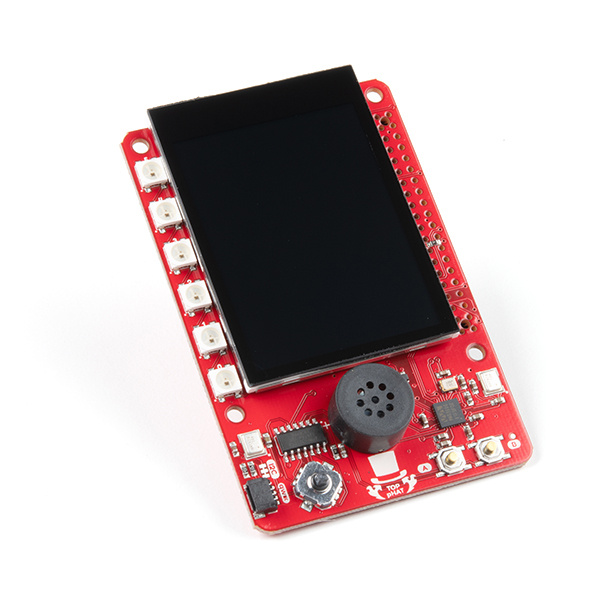
Drum roll please... Introducing, the Top pHAT! The pHAT for the top of all your other HATs. Ta-da!!! It makes the perfect GIF(t).

Source: GIPHY
Haha... all jokes aside, this pHAT comes bundled with multiple goodies to begin your Raspberry Pi adventure; including a 2.3" TFT screen, which would be a shame to cover up other HATs.
SparkFun Top pHAT for Raspberry Pi
DEV-16301SparkFun Top pHAT for Raspberry Pi
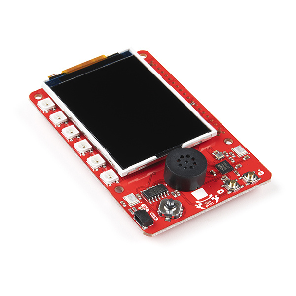
DEV-16653Additionally, on the Top pHAT you will find the following components:
- 6 addressable WS2812 RGB LEDs
- 2 MEMS microphones
- A mono speaker
There are dozens of applicable projects for this product, you can even use it to get started with your machine learning applications. The limits are up to you.
Required Materials
The required materials will depend on your project. However, at minimum, users will need a Raspberry Pi, an SD card, and a power supply (or power source). Users can include additional accessories and peripherals for their setup.
Raspberry Pi
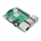
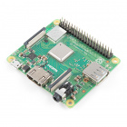
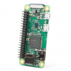
Each of the models of the Raspberry Pi that we offer have a unique facets that separate them from each other.
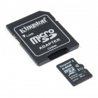
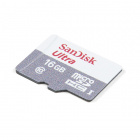
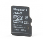
SD Cards
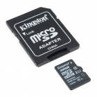
These SD cards in our catalog are tested and known to work with all the models of the Raspberry Pi. For first time users, we recommend using the NOOBS version as it has the required OS pre-installed.
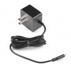
Power Supplies
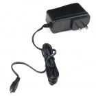
These power supplies in our catalog are tested and known to work with the Raspberry Pi models in our catalog.
⚡ Note:
The Raspberry Pi 3 and Zero models require a micro-USB power supply. We recommend using the 5.1V 2.5A power supply.
The Raspberry Pi 4 models require a USB-C power supply.We recommend using the Official Raspberry Pi power supply to avoid this issue.
Extension Header
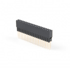
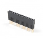
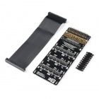
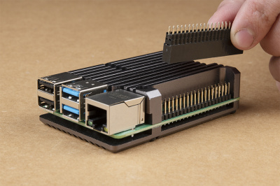
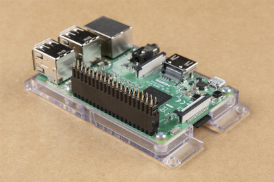
As noted in a previous section, an extension header is required for the Raspberry Pi 3 and Pi 4 to provided enough clearance between the Top pHAT and Raspberry Pi.
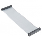
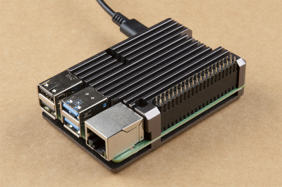
This is especially important for a Raspberry Pi 4 with heat sink case, which may require multiple headers to allow air flow for thermal dissipation. There are some alternatives for that, listed above.
Peripherals
For users looking to use the desktop graphical user interface (GUI), they will also need the following:
- TV, Display, or Monitor
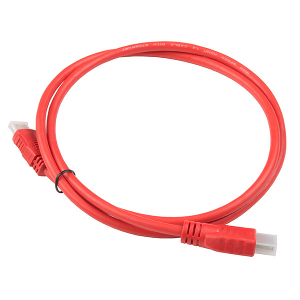
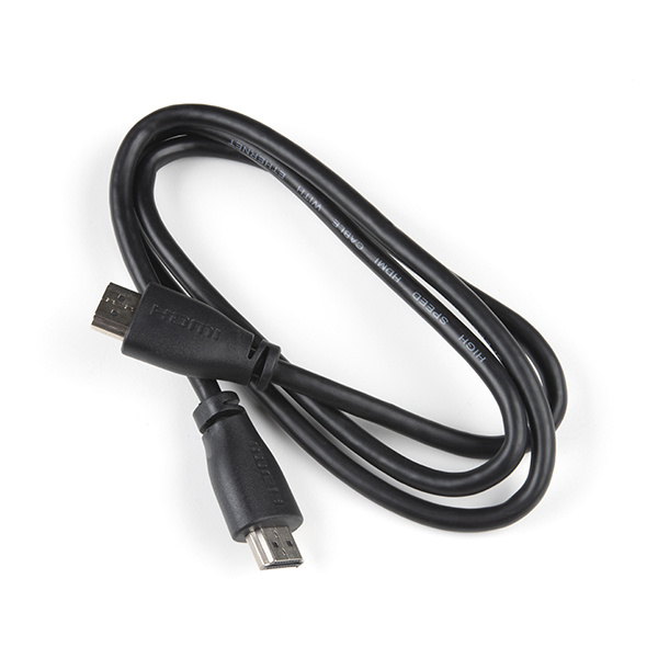
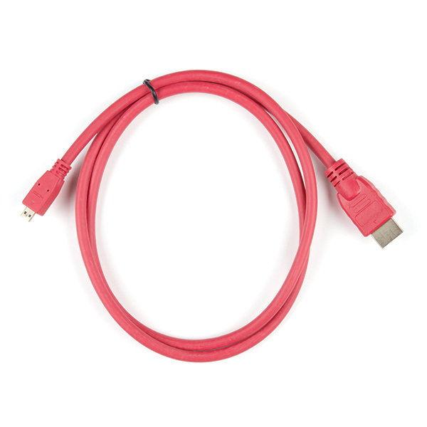
- Compatible HDMI Cable
- USB Keyboard and Mouse
Displays
For beginners we recommend using a modern TV (i.e. with an HDMI input) or computer monitor, as it will undoubtedly be easier and more intuitive for users to setup.
Compatible HDMI Cable
If you don't have an HDMI cable (and possible adapter), these have been tested to work with following Raspberry Pi models:
Note: If your display doesn't have an HDMI input, you will need to source an appropriate adapter. There are DVI and VGA to HDMI adapters, that will work on older computer monitors. Unfortunately, we don't have any adapters or a list of optional products for more outdated inputs (i.e. RCA, S-video, Component, or coaxial inputs).
USB Keyboard and Mouse
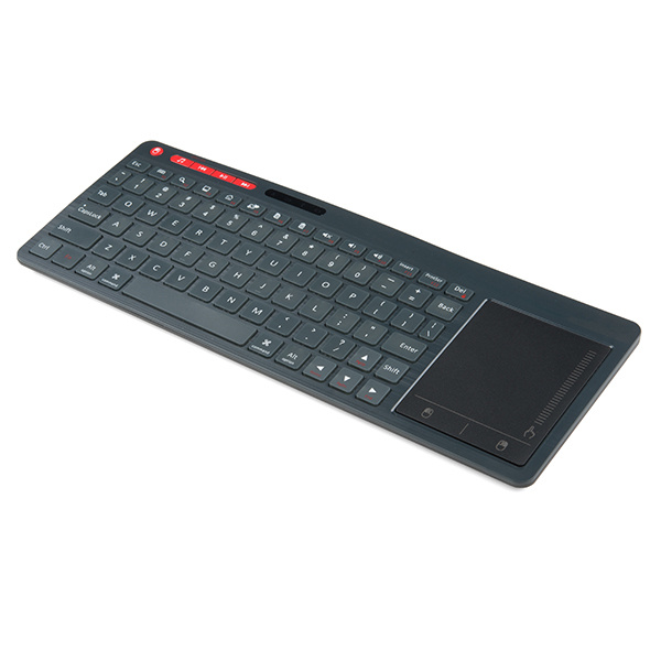
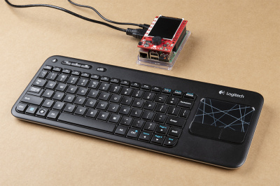
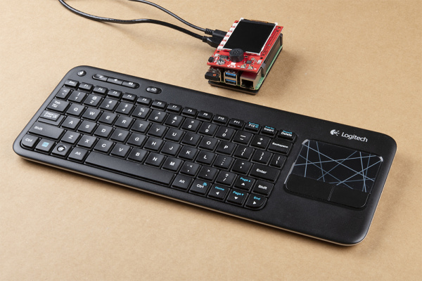
If you don't already have a USB keyboard and mouse, we do offer a multimedia keyboard that has been tested as a plug-and-play option for the Raspberry Pi models in our catalog.
Note: This keyboard is similar to a smaller laptop form factor in the button layout. Users with the Raspberry Pi Zero W models will need an additional USB (OTG) cable.
Raspberry Pi Kits
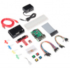
Additionally, we do offer Raspberry Pi kits, which will include some of the accessories first-time users may already need.
SparkFun Raspberry Pi 4 Basic Kit - 4GB
KIT-16384SparkFun Raspberry Pi Zero W Basic Kit
KIT-14298Raspberry Pi 3 B+ Starter Kit
KIT-15361Suggested Reading
Note: First time users should also head over to the Raspberry Pi Foundation website and check out their quickstart guides:
- Blog Post: Getting started with your Raspberry Pi
- Raspberry Pi Foundation Getting Stared Guides:
- MagPi Books and Guides:
- Article: Get started with your new Raspberry Pi
- The Offical Raspberry Pi Beginner’s Book (December 2017)
- Get Started with Raspberry Pi (November 2019)
- The Offical Raspberry Pi Beginner’s Guide: How to use your new computer
1st Edition (December 2018)
2nd Edition (June 2019)
3rd Edition (November 2019)
We have also listed a few additional resources for users to familiarize themselves with the Raspberry Pi:
Below are some of our Raspberry Pi related tutorials that may be of interest to beginners:
Serial Peripheral Interface (SPI)
Logic Levels
I2C
Serial Terminal Basics
SD Cards and Writing Images
Raspberry Pi SPI and I2C Tutorial
Headless Raspberry Pi Setup
Python Programming Tutorial: Getting Started with the Raspberry Pi
How to Use Remote Desktop on the Raspberry Pi with VNC
How to Run a Raspberry Pi Program on Startup
Hardware Overview
Below, is an overview of all the hardware included on the Top pHAT.
Dimensions
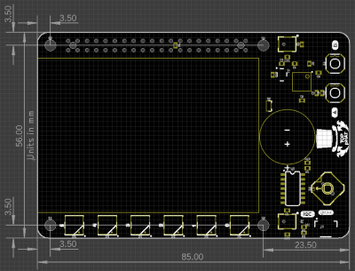
The overall dimensions of the Top pHAT are 56mm x 85mm. Don't forget to account for the small overhang of the display's ribbon cable, which wraps around the left edge of the board. For more details, users can check out the layout in the Eagle files.
GPIO Connections
As the Top pHAT is also intended to integrate with other HATs, it is important to know all of the pin being utilized to avoid conflicts. Below is a layout of all the GPIO pins being utilized by the hardware on the Top pHAT.
Power Connections
Power to the Top pHAT is supplied through the GPIO pins; both 5V and 3.3V are utilized.
| Pin # | GPIO |
|---|---|
| 1 | 3.3V |
| 17 | 3.3V |
| 2 | 5V |
| 4 | 5V |
| 6 | GND |
| 9 | GND |
| Pin # | GPIO |
|---|---|
| 14 | GND |
| 20 | GND |
| 30 | GND |
| 34 | GND |
| 39 | GND |
WM8960 Stereo CODEC (I2S)
| Pin # | GPIO | Function |
|---|---|---|
| 12 | GPIO 18 (PCM_CLK) | BCLK |
| 35 | GPIO 19 (PCM_FS) | DAC-LRC |
| 38 | GPIO 20 (PCM_DIN) | ADC-DAT |
| 40 | GPIO 21 (PCM_DOUT | DAC-DAT |
WS2812 RGB LEDs
| Pin # | GPIO | Function |
|---|---|---|
| 32 | GPIO 12 (PWM0) | Data In |
2.4” TFT LCD Display (SPI)
| Pin # | GPIO | Function |
|---|---|---|
| 15 | GPIO 22 | Backlight |
| 16 | GPIO 23 | RESET |
| 18 | GPIO 24 | DC |
| 19 | GPIO 10 (COPI) | SDI |
| 21 | GPIO 09 (CIPO) | SDO |
| 23 | GPIO 11 (SCLK) | SCK |
| 24 | GPIO 08 (CE0) | CS |
Qwiic (I2C)
Qwiic Connector
| Pin # | GPIO | Function |
|---|---|---|
| 3 | GPIO 02 (SDA) | Qwiic (SDA) |
| 5 | GPIO 03 (SCL) | Qwiic (SCL) |
Button Controller (I2C)
| Pin # | GPIO | Function |
|---|---|---|
| 3 | GPIO 02 (SDA) | Qwiic (SDA) |
| 5 | GPIO 03 (SCL) | Qwiic (SCL) |
| 22 | GPIO 25 | Button Interrupt |
Audio (I2S)
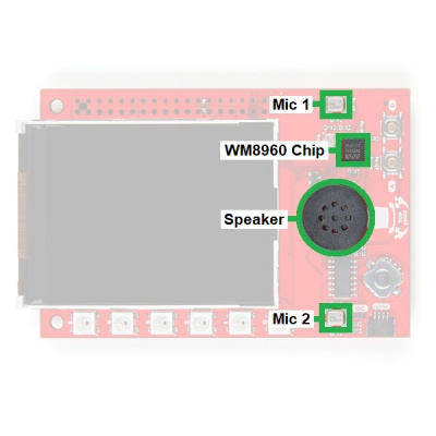
There are four audio components on the Top pHAT; an audio codec, two MEMs microphones, and a speaker. They controlled by the Raspberry Pi using an I2S protocol. The WM8960 stereo codec is the driver behind the audio components. It is used to both drive the speaker output and to control the microphone interface. The MEMs microphones and speaker are used as the input and output components of the audio interface.
2.4" TFT LCD Display (SPI)
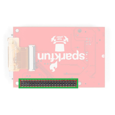
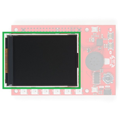
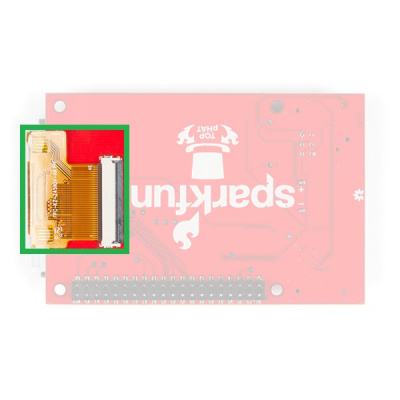
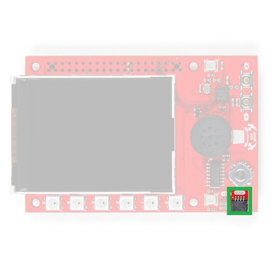
The screen on the Top pHAT is most prevalent component on the Top pHAT. The 2.4" TFT LCD Display has a native resolution of 240 x 320 pixels and is backlit by four LEDs. The screen can be replaced using the 40 Pin 0.5mm FPC connector on the bottom of the Top pHAT. (*When replacing the screen, users should verify the replacement has the appropriate connections, driver, and configured in the operating system.)
WS2812 RGB LEDs
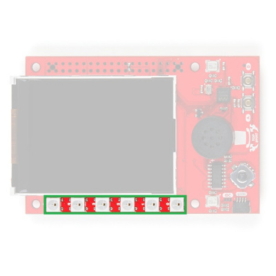
There are six addressable RGB WS2812 LEDs on the board. These can be used as indicators, for when you might be too far way to read the screen, but it is still in your line of sight. These LEDs can get very bright; therefore, we recommend using a lower brightness setting.
Qwiic (I2C)
Qwiic is the name of our simple to use connector for I2C devices. It provides a simple, solderless, and polarized connection that should be impossible to mess up. (In case you were wondering, Qwiic is a play on words between quick and I2C.)
Button Controller
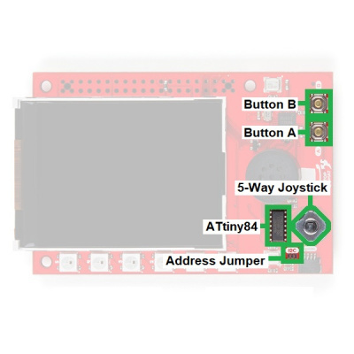
Although not an official Qwiic device, the button controller is accessed through the I2C interface. The controller is an ATtiny84, which emulates an I2C peripheral device and is used to read the 5-way switch and two momentary buttons. An interrupt pin is available for more immediate responses.
Qwiic Connector
A connector is provided for attaching other Qwiic devices.
Note: While most of our Qwiic devices should be compatible with the Raspberry Pi, not all have a supported Python package. Users who are unfamiliar with our Qwiic connect system, can check out the video below:
Hardware Assembly
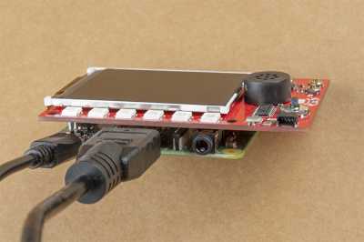
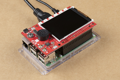
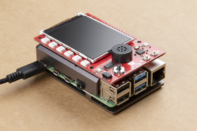
Assembly for the Top pHAT is fairly straight forward. It plugs directly into the GPIO pins of a Raspberry Pi. Most importantly, users need pay attention to the orientation of the pHAT and double check that the pin are lined up properly. below are a few examples for users to follow.
(Click images to enlarge)
If the clearance between the pHAT and the Raspberry Pi components (including things like a case or heat sink) becomes an issue, a header can be used to increase the spacing.
To configure the Raspberry Pi for use with the Top pHAT, the PIXEL desktop is recommended. It will be the most convenient for users, but users can still use other methods like SSH to remotely access the Raspberry Pi. To utilize the desktop, users will need to add peripherals like a monitor and keyboard.
(Click images to enlarge)
OS Configuration: Part 1
Configuring the Raspbian OS for the Top pHAT is relatively simple. The SPI and I2C interfaces need to be enabled along with the overscan disabled. (Users wishing to use the screen on boot will also need to configure the OS to boot to the CLI and run the frame buffer mapping script on startup. Directions will be laid out in OS Configuration: Part 2; however, users should do this last.)
Configuration Methods
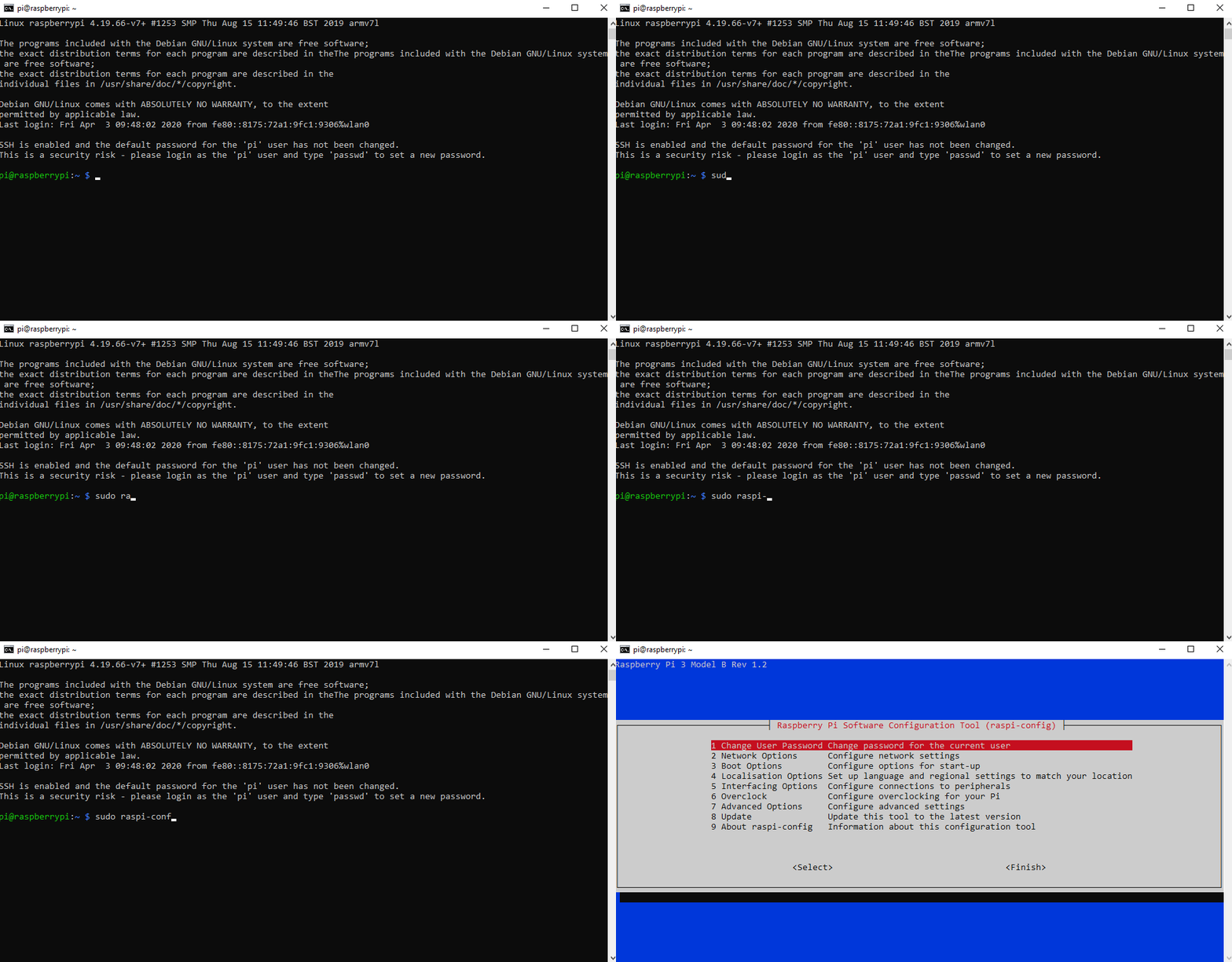
There are 2 primary methods for configuring the Raspbian OS. Within the Raspberry Pi PIXEL desktop, the graphical Raspberry Pi Configuration application from the Preferences menu is the most user friendly option. Users can also make changes through the console based raspi-config application.
(*For more details on the operating system configuration, check out the Raspberry Pi Foundation website.)
Disable Overscan
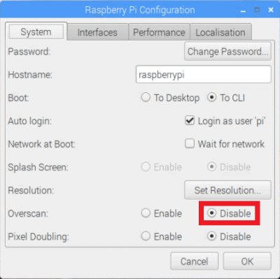
Users will want to disable overscan through the System or Advanced Options menus.
Raspberry Pi Configuration Application
On the main System tab, disable the Overscan and then move on to the next section to enable the SPI and I2C interfaces.
Raspi-Config Application
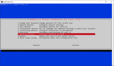
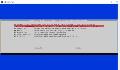
From the 7 Advanced Options menu, select the A2 Overscan option and then follow the prompts to disable the overscan. Move on the next section to enable the SPI and I2C interfaces.
Advanced Options menu in the console based raspi-config application. (Click to enlarge) Overscan option to disable it, using the prompts. (Click to enlarge) Enable SPI and I2C
Users will need to enable both the SPI and I2C interfaces through the Interface menu.
Raspberry Pi Configuration Application
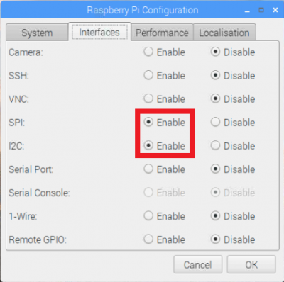
From the Interfaces tab, enable both the SPI and I2C interfaces.
SPI and I2C interfaces through the Raspberry Pi Configuration application. Once done, click the OK button. Reboot the Raspberry Pi when prompted.
Raspi-Config Application
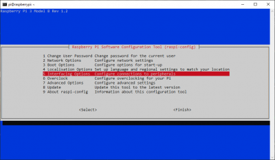
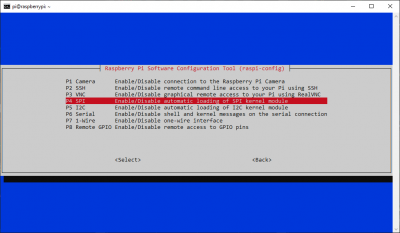
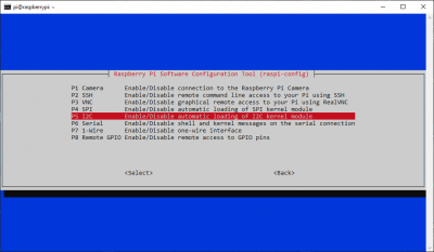
From the 5 Interfaces Options menu, select the P4 SPI option and then follow the prompts to enable the interface.
Interfaces Options menu in the console based raspi-config application. (Click to enlarge) SPI option to enable the interface, using the prompts. (Click to enlarge) Repeat the previous steps, but select the P5 I2C option; again, following the prompts to enable the interface.
I2C option to enable the interface, using the prompts. (Click to enlarge) Once completed, use the Tab key to select the <Finish> button. Reboot the Raspberry Pi when prompted.
Button Controller
Note: This tutorial assumes you are using the latest version of Python 3. If this is your first time using Python or I2C hardware on a Raspberry Pi, please checkout our tutorial on Python Programming with the Raspberry Pi and the Raspberry Pi SPI and I2C Tutorial.
We've written a Python package to easily get setup and take readings from the button controller on the Top pHAT. There are two methods for installing the Python package for the button controller.
- Install the all inclusive SparkFun Qwiic Python package.
- Independently install the SparkFun Top pHAT Button Python package.
The all inclusive SparkFun Qwiic Python package, is recommended as is also installs the required I2C driver as well.
Note: Don't forget to double check that the hardware I2C connection is enabled on your Raspberry Pi or other single board computer.
SparkFun Qwiic Package
This repository is hosted on PyPi as the sparkfun-top-phat-button package. On systems that support PyPi installation via pip3 (use pip for Python 2) is simple, using the following commands:
For all users (note: the user must have sudo privileges):
language:bash
sudo pip3 install sparkfun-qwiic
For the current user:
language:bash
pip3 install sparkfun-qwiic
Independent Installation
You can install the sparkfun-top-phat-button Python package independently, which is hosted by PyPi. However, if you prefer to manually download and install the package from the GitHub repository, you can grab them here (*Please be aware of any package dependencies. You can also check out the repository documentation page, hosted on ReadtheDocs.):
PyPi Installation
This repository is hosted on PyPi as the sparkfun-top-phat-button package. On systems that support PyPi installation via pip3 (use pip for Python 2) is simple, using the following commands:
For all users (note: the user must have sudo privileges):
language:bash
sudo pip3 install sparkfun-top-phat-button
For the current user:
language:bash
pip3 install sparkfun-top-phat-button
Local Installation
To install, make sure the setuptools package is installed on the system.
Direct installation at the command line (use python for Python 2):
language:bash
python3 setup.py install
To build a package for use with pip3:
language:bash
python3 setup.py sdist
A package file is built and placed in a subdirectory called dist. This package file can be installed using pip3.
language:bash
cd dist
pip3 install sparkfun_top_phat_button-<version>.tar.gz
Python Package Operation
Before we jump into getting readings, let's take a closer look at the available functions in the Python package. Below, is a description of the basic functionality of the Python package. This includes the package organization, built-in methods, and their inputs and/or outputs. For more details on how the Python package works, check out the source code, the firmware, and package documentation.
Dependencies
This Python package has a very few dependencies in the code, listed below:
language:python
from __future__ import print_function
import qwiic_i2c
Default Variables
The default variables, in the code, for this Python package are listed below:
language:python
# Some devices have multiple availabel addresses - this is a list of these addresses.
# NOTE: The first address in this list is considered the default I2C address for the
# device.
_AVAILABLE_I2C_ADDRESS = [0x71]

# Register codes for the Joystick
BUTTON_ID               = 0x00
BUTTON_VERSION1         = 0x01
BUTTON_VERSION2         = 0x02
BUTTON_PRESSED          = 0x03
BUTTON_CLICKED          = 0x04
BUTTON_INTERRUPT        = 0x05
BUTTON_DEBOUNCE         = 0x06
BUTTON_CHANGE_ADDREESS  = 0x1F

# Define the bit positions of the buttons and interrupt flag
A                     = 0
B                     = 1
UP                    = 2
DOWN                  = 3
LEFT                  = 4
RIGHT                 = 5
CENTER                = 6
EVENT_AVAILABLE       = 7

# Define the positions of the Interrupt Enable Bits
CLICKED_INTERRUPT_ENABLE        = 0
PRESSED_INTERRUPT_ENABLE        = 1
Class
ToppHATButton() or ToppHATButton(address)
This Python package operates as a class object, allowing new instances of that type to be made. An __init__() constructor is used that creates a connection to an I2C device over the I2C bus using the default or specified I2C address.
The Constructor
A constructor is a special kind of method used to initialize (assign values to) the data members needed by the object when it is created.
__init__(address=None, i2c_driver=None):
_AVAILABLE_I2C_ADDRESS variable.qwiic_i2c.getI2CDriver(). Users should use the default I2C driver and leave this field blank.Functions
A function that is an attribute of the class, which defines a method for instances of that class. In simple terms, they are objects for the operations (or methods) of the class.
.is_connected()
Determines if the button controller device is connected to the system.
True: Connected to I2C device on the default (or specified) address.
False: No device found or connected.
.begin()
Initialize the operation of the button controller. (Basically tests the connection to the button controller.)
True: The initialization was successful.
False: Initialization failed.
.get_button_pressed()
Updates and returns buffer for all buttons and whether or not they are pressed as well as the pressed interrupt flag.
    Reading this register also clears it.
    7(MSB)  6    5    4    3    2    1    0(LSB)
      INT  CTR  RGT  LFT  DWN   UP   B    A
Returns 1 bit when a button is currently being pressed, based on the mapping above. The interrupt must be cleared by the user.
0: No interrupt; no buttons currently pressed.
1: No interrupt; only Button A is currently being pressed.
2: No interrupt; only Button B is currently being pressed.
3: No interrupt; Button A and Button B are currently being pressed./br>
.
.
.
195: Interrupt; Button A and Button B are currently being pressed. The 5-way switch is currently being pressed with the Center pad.
196-255: Are not possible as the 5-way switch cannot indicate multiple directions.
.get_button_clicked()
Updates and returns buffer for all buttons and whether or not they have been clicked as well as the clicked interrupt flag.
    Reading this register also clears it.
    7(MSB)  6    5    4    3    2    1    0(LSB)
      INT  CTR  RGT  LFT  DWN   UP   B    A
Returns 1 when a button has received a full click cycle (press and release). The interrupt must be cleared by the user.
0: No interrupt; no buttons were clicked.
1: No interrupt; only Button A was clicked.
2: No interrupt; only Button B was clicked.
3: No interrupt; Button A and Button B were clicked.
.
.
.
254: Interrupt; Button B was clicked. The 5-way switch, was clicked in all directions, including the Center pad.
255: Interrupt; Button A and Button B were clicked. The 5-way switch, was clicked in all directions, including the Center pad.
.get_version()
Returns a string of the firmware version number.
The firmware version
.get_pressed_interrupt()
Returns the status of the pressed interrupt enable.
The value of the interrupt enable bit.
.set_pressed_interrupt(bit_setting)
Sets the status of the pressed interrupt enable bit.
0: The pressed interrupt enable bit.
1: The pressed interrupt enable bit.
0: I2C transaction failed, the interrupt enable bit wasn't set.
1: I2C transaction succeeded, the interrupt enable bit was set.
.get_clicked_interrupt()
Returns the status of the clicked interrupt enable.
The value of the clicked interrupt enable bit.
.set_clicked_interrupt(bit_setting)
Sets the status of the clicked interrupt enable bit.
0: The clicked interrupt enable bit.
1: The clicked interrupt enable bit.
0: I2C transaction failed, the interrupt enable bit wasn't set.
1: I2C transaction succeeded, the interrupt enable bit was set.
Upgrading the Python Package
In the future, changes to the Python package might be made. Updating the installed packages has to be done individually for each package (i.e. sub-modules and dependencies won't update automatically and must be updated manually). For the sparkfun-top-phat-button Python package, use the following command (use pip for Python 2):
For all users (note: the user must have sudo privileges):
language:bash
sudo pip3 install --upgrade sparkfun-top-phat-button
For the current user:
language:bash
pip3 install --upgrade sparkfun-top-phat-button
Python Examples
There are two examples written for the Top pHAT using this Python package. They can be found in the GitHub repository or viewed in the ReadtheDocs documentation
Example 1
Example 1 utilizes the interrupt for more immediate responses.
#!/usr/bin/env python
#-----------------------------------------------------------------------------
# top_phat_button_ex1.py
#
# Polling example for the Top pHAT Buttons
#------------------------------------------------------------------------
#
# Written by  SparkFun Electronics, April 2020
#
# This python library supports the SparkFun Electroncis qwiic
# qwiic sensor/board ecosystem on a Raspberry Pi (and compatable) single
# board computers.
#
# More information on qwiic is at https://www.sparkfun.com/qwiic
#
# Do you like this library? Help support SparkFun. Buy a board!
#
#==================================================================================
# Copyright (c) 2019 SparkFun Electronics
#
# Permission is hereby granted, free of charge, to any person obtaining a copy
# of this software and associated documentation files (the "Software"), to deal
# in the Software without restriction, including without limitation the rights
# to use, copy, modify, merge, publish, distribute, sublicense, and/or sell
# copies of the Software, and to permit persons to whom the Software is
# furnished to do so, subject to the following conditions:
#
# The above copyright notice and this permission notice shall be included in all
# copies or substantial portions of the Software.
#
# THE SOFTWARE IS PROVIDED "AS IS", WITHOUT WARRANTY OF ANY KIND, EXPRESS OR
# IMPLIED, INCLUDING BUT NOT LIMITED TO THE WARRANTIES OF MERCHANTABILITY,
# FITNESS FOR A PARTICULAR PURPOSE AND NONINFRINGEMENT. IN NO EVENT SHALL THE
# AUTHORS OR COPYRIGHT HOLDERS BE LIABLE FOR ANY CLAIM, DAMAGES OR OTHER
# LIABILITY, WHETHER IN AN ACTION OF CONTRACT, TORT OR OTHERWISE, ARISING FROM,
# OUT OF OR IN CONNECTION WITH THE SOFTWARE OR THE USE OR OTHER DEALINGS IN THE
# SOFTWARE.
#==================================================================================
# Example 1
#

from __future__ import print_function
import top_phat_button
import time
import sys

myButtons = top_phat_button.ToppHATButton()

def runExample():

    print("\nSparkFun Top pHAT Button  Example 1\n")

    if myButtons.is_connected() == False:
        print("The Top pHAT Button device isn't connected to the system. Please check your connection", \
            file=sys.stderr)
        return

    myButtons.pressed_interrupt_enable = False
    myButtons.clicked_interrupt_enable = False

    while True:
        myButtons.button_pressed #These functions must be called to update button variables to their latest setting
        myButtons.button_clicked #These functions must be called to update button variables to their latest setting
        if myButtons.a_pressed == True:
            print("A Pressed")
        if myButtons.a_clicked == True:
            print("A Released")
        if myButtons.b_pressed == True:
            print("B Pressed")
        if myButtons.b_clicked == True:
            print("B Released")
        if myButtons.up_pressed == True:
            print("Up Pressed")
        if myButtons.up_clicked == True:
            print("Up Released")
        if myButtons.down_pressed == True:
            print("Down Pressed")
        if myButtons.down_clicked == True:
            print("Down Released")
        if myButtons.left_pressed == True:
            print("Left Pressed")
        if myButtons.left_clicked == True:
            print("Left Released")
        if myButtons.right_pressed == True:
            print("Right Pressed")
        if myButtons.right_clicked == True:
            print("Right Released")
        if myButtons.center_pressed == True:
            print("Center Pressed")
        if myButtons.center_clicked == True:
            print("Center Released")

        time.sleep(.1)


if __name__ == '__main__':
    try:
        runExample()
    except (KeyboardInterrupt, SystemExit) as exErr:
        print("\nEnding Example 1")
        sys.exit(0)
Example 2
Example 2 doesn't utilize the interrupt and must constantly ping the button controller for updates on potential actions performed on the buttons.
#!/usr/bin/env python
#-----------------------------------------------------------------------------
# top_phat_button_ex2.py
#
# Interrupt example for the Top pHAT Buttons
#------------------------------------------------------------------------
#
# Written by  SparkFun Electronics, April 2020
#
# This python library supports the SparkFun Electroncis qwiic
# qwiic sensor/board ecosystem on a Raspberry Pi (and compatable) single
# board computers.
#
# More information on qwiic is at https://www.sparkfun.com/qwiic
#
# Do you like this library? Help support SparkFun. Buy a board!
#
#==================================================================================
# Copyright (c) 2019 SparkFun Electronics
#
# Permission is hereby granted, free of charge, to any person obtaining a copy
# of this software and associated documentation files (the "Software"), to deal
# in the Software without restriction, including without limitation the rights
# to use, copy, modify, merge, publish, distribute, sublicense, and/or sell
# copies of the Software, and to permit persons to whom the Software is
# furnished to do so, subject to the following conditions:
#
# The above copyright notice and this permission notice shall be included in all
# copies or substantial portions of the Software.
#
# THE SOFTWARE IS PROVIDED "AS IS", WITHOUT WARRANTY OF ANY KIND, EXPRESS OR
# IMPLIED, INCLUDING BUT NOT LIMITED TO THE WARRANTIES OF MERCHANTABILITY,
# FITNESS FOR A PARTICULAR PURPOSE AND NONINFRINGEMENT. IN NO EVENT SHALL THE
# AUTHORS OR COPYRIGHT HOLDERS BE LIABLE FOR ANY CLAIM, DAMAGES OR OTHER
# LIABILITY, WHETHER IN AN ACTION OF CONTRACT, TORT OR OTHERWISE, ARISING FROM,
# OUT OF OR IN CONNECTION WITH THE SOFTWARE OR THE USE OR OTHER DEALINGS IN THE
# SOFTWARE.
#==================================================================================
# Example 2
#

from __future__ import print_function
import top_phat_button
import time
import sys
import RPi.GPIO as GPIO

INTERRUPT_PIN = 25
GPIO.setmode(GPIO.BCM)
GPIO.setup(INTERRUPT_PIN, GPIO.IN)

myButtons = top_phat_button.ToppHATButton()

def interruptCallback(channel):
    myButtons.button_pressed
    myButtons.button_clicked #Both interrupts are configured, so we need to read both registers to clear the interrupt and update our button data.
    if myButtons.a_pressed == True:
        print("A Pressed")
    if myButtons.a_clicked == True:
        print("A Released")
    if myButtons.b_pressed == True:
        print("B Pressed")
    if myButtons.b_clicked == True:
        print("B Released")
    if myButtons.up_pressed == True:
        print("Up Pressed")
    if myButtons.up_clicked == True:
        print("Up Released")
    if myButtons.down_pressed == True:
        print("Down Pressed")
    if myButtons.down_clicked == True:
        print("Down Released")
    if myButtons.left_pressed == True:
        print("Left Pressed")
    if myButtons.left_clicked == True:
        print("Left Released")
    if myButtons.right_pressed == True:
        print("Right Pressed")
    if myButtons.right_clicked == True:
        print("Right Released")
    if myButtons.center_pressed == True:
        print("Center Pressed")
    if myButtons.center_clicked == True:
        print("Center Released")

GPIO.add_event_detect(INTERRUPT_PIN, GPIO.FALLING, callback=interruptCallback, bouncetime=5)

def runExample():

    print("\nSparkFun Top pHAT Button  Example 1\n")

    if myButtons.is_connected() == False:
        print("The Top pHAT Button device isn't connected to the system. Please check your connection", \
            file=sys.stderr)
        return

    myButtons.pressed_interrupt_enable = True
    myButtons.clicked_interrupt_enable = True #Enable both hardware interrupts

    while True:

        time.sleep(.1)


if __name__ == '__main__':
    try:
        runExample()
    except (KeyboardInterrupt, SystemExit) as exErr:
        print("\nEnding Example 1")
        sys.exit(0)
WS2812B LEDs
Note: This tutorial assumes you are using the latest version of Python 3. If this is your first time using Python or I2C hardware on a Raspberry Pi, please checkout our tutorial on Python Programming with the Raspberry Pi and the Raspberry Pi SPI and I2C Tutorial.
For the addressable LEDs, we will be using Adafruit's neopixel python package. The adafruit-circuitpython-neopixel Python package is hosted on PyPi.
PyPi Installation
On systems that support PyPi installation via pip3 (use pip for Python 2) is simple, using the following commands:
For all users (note: the user must have sudo privileges):
language:bash
sudo pip3 install adafruit-circuitpython-neopixel
For the current user:
language:bash
pip3 install adafruit-circuitpython-neopixel
sudo command.Python Examples
Before users jump into operating the LEDs, it is recommended that they review the the Read the Docs documentation for the Python package and datasheet for the WS2812B LEDs. Below are a few examples for using the LEDs on the Top pHAT; don't forget that the LEDs are attached to pin 12 and
Example 1
This is a basic example setting the first, fourth, and fifth LEDs. The array is RGB, with the value indicating the brightness magnitude (0-255).
language:python
# Import Dependencies
import board
import neopixel

# Create the class object
pixels = neopixel.NeoPixel(board.D12, 6, auto_write=False)

# Set Pixel Configuration
pixels[0] = (10, 0, 0)
pixels[3] = (0, 10, 0)
pixels[4] = (0, 0, 10)

# Display Configuration
pixels.show()
Example 2
This is a basic example cycles through the LEDs individually setting them green.
language:python
# Import Dependencies
import board
import neopixel
import time

# Create the class object
pixels = neopixel.NeoPixel(board.D12, 6)

while True:
    for i in range(6):
        # Clear previous LED
        if i == 0:
            pixels[5] = (0,0,0)
        else:
            pixels[i-1]=(0,0,0)

        # Set LED green
        pixels[i]=(0,10,0)

        # Delay
        time.sleep(.2)
WM8960 Audio Codec
Getting the audio components up an operational involves two steps; installing the driver for the WM8960 audio codec and configuring the default sound card in the OS. We will be following the installation instructions from Waveshare for their Audio HAT.
Audio Codec Driver
To install the driver for the WM8960 audio codec, enter the following lines into the terminal or CLI.
language:bash
git clone https://github.com/waveshare/WM8960-Audio-HAT
cd WM8960-Audio-HAT
sudo ./install.sh
sudo reboot
If the installation is done properly, the output in the terminal should look like this:
language:bash
pi@raspberrypi:~ $ git clone https://github.com/waveshare/WM8960-Audio-HAT
Cloning into 'WM8960-Audio-HAT'...
remote: Enumerating objects: 3, done.
remote: Counting objects: 100% (3/3), done.
remote: Compressing objects: 100% (3/3), done.
remote: Total 51 (delta 0), reused 0 (delta 0), pack-reused 48
Unpacking objects: 100% (51/51), done.

pi@raspberrypi:~ $ cd WM8960-Audio-HAT

pi@raspberrypi:~ $ sudo ./install.sh

pi@raspberrypi:~/WM8960-Audio-HAT $ sudo ./install.sh
Get:1 http://archive.raspberrypi.org/debian stretch InRelease [25.4 kB]
Get:2 http://raspbian.raspberrypi.org/raspbian stretch InRelease [15.0 kB]
Get:3 http://archive.raspberrypi.org/debian stretch/main armhf Packages [220 kB]
Get:4 http://raspbian.raspberrypi.org/raspbian stretch/main armhf Packages [11.7 MB]
Fetched 11.9 MB in 17s (699 kB/s)
Reading package lists... Done
Building dependency tree
Reading state information... Done
52 packages can be upgraded. Run 'apt list --upgradable' to see them.
Reading package lists... Done
Building dependency tree
Reading state information... Done
raspberrypi-kernel is already the newest version (1.20190819~stretch-1).
raspberrypi-kernel-headers is already the newest version (1.20190819~stretch-1).
0 upgraded, 0 newly installed, 0 to remove and 52 not upgraded.
1 not fully installed or removed.
After this operation, 0 B of additional disk space will be used.
Setting up python-sense-emu (1.1) ...
Traceback (most recent call last):
  File "/usr/bin/pycompile", line 35, in <module>
    from debpython.version import SUPPORTED, debsorted, vrepr, \
  File "/usr/share/python/debpython/version.py", line 24, in <module>
    from ConfigParser import SafeConfigParser
ImportError: No module named 'ConfigParser'
dpkg: error processing package python-sense-emu (--configure):
 subprocess installed post-installation script returned error exit status 1
Errors were encountered while processing:
 python-sense-emu
E: Sub-process /usr/bin/dpkg returned an error code (1)
Reading package lists... Done
Building dependency tree
Reading state information... Done
dkms is already the newest version (2.3-2).
i2c-tools is already the newest version (3.1.2-3).
i2c-tools set to manually installed.
Suggested packages:
  git-daemon-run | git-daemon-sysvinit git-doc git-el git-email git-gui gitk gitweb git-arch git-cvs git-mediawiki
  git-svn
The following NEW packages will be installed:
  libasound2-plugins
The following packages will be upgraded:
  git
1 upgraded, 1 newly installed, 0 to remove and 51 not upgraded.
1 not fully installed or removed.
Need to get 3,462 kB of archives.
After this operation, 293 kB of additional disk space will be used.
Get:1 http://mirror.sjc02.svwh.net/raspbian/raspbian stretch/main armhf git armhf 1:2.11.0-3+deb9u5 [3,389 kB]
Get:2 http://mirror.sjc02.svwh.net/raspbian/raspbian stretch/main armhf libasound2-plugins armhf 1.1.1-1 [72.9 kB]
Fetched 3,462 kB in 1s (2,536 kB/s)
apt-listchanges: Reading changelogs...
(Reading database ... 141372 files and directories currently installed.)
Preparing to unpack .../git_1%3a2.11.0-3+deb9u5_armhf.deb ...
Unpacking git (1:2.11.0-3+deb9u5) over (1:2.11.0-3+deb9u4) ...
Selecting previously unselected package libasound2-plugins:armhf.
Preparing to unpack .../libasound2-plugins_1.1.1-1_armhf.deb ...
Unpacking libasound2-plugins:armhf (1.1.1-1) ...
Setting up python-sense-emu (1.1) ...
Traceback (most recent call last):
  File "/usr/bin/pycompile", line 35, in <module>
    from debpython.version import SUPPORTED, debsorted, vrepr, \
  File "/usr/share/python/debpython/version.py", line 24, in <module>
    from ConfigParser import SafeConfigParser
ImportError: No module named 'ConfigParser'
dpkg: error processing package python-sense-emu (--configure):
 subprocess installed post-installation script returned error exit status 1
Setting up libasound2-plugins:armhf (1.1.1-1) ...
Setting up git (1:2.11.0-3+deb9u5) ...
Errors were encountered while processing:
 python-sense-emu
E: Sub-process /usr/bin/dpkg returned an error code (1)

Creating symlink /var/lib/dkms/wm8960-soundcard/1.0/source ->
                 /usr/src/wm8960-soundcard-1.0

DKMS: add completed.

Kernel preparation unnecessary for this kernel.  Skipping...

Building module:
cleaning build area....
make -j4 KERNELRELEASE=4.19.66-v7+ -C /lib/modules/4.19.66-v7+/build M=/var/lib/dkms/wm8960-soundcard/1.0/build............
cleaning build area....

DKMS: build completed.

snd-soc-wm8960:
Running module version sanity check.
 - Original module
   - No original module exists within this kernel
 - Installation
   - Installing to /lib/modules/4.19.66-v7+/kernel/sound/soc/codecs/

snd-soc-wm8960-soundcard.ko:
Running module version sanity check.
 - Original module
   - No original module exists within this kernel
 - Installation
   - Installing to /lib/modules/4.19.66-v7+/kernel/sound/soc/bcm/

depmod....

DKMS: install completed.
Created symlink /etc/systemd/system/sysinit.target.wants/wm8960-soundcard.service → /lib/systemd/system/wm8960-soundcard.service.
------------------------------------------------------
Please reboot your raspberry pi to apply all settings
Enjoy!
------------------------------------------------------

pi@raspberrypi:~ $ sudo reboot
Driver Installation Verification
To verify that the audio driver installation was successful and the kernel was rebuilt, use the sudo dkms status command in the terminal or CLI. Users should a response similar to:
language:bash
wm8960-soundcard, 1.0, 4.19.66-v7+, armv7l: installed
Playback Devices
For further verification, users can list the playback devices using the aplay -l command in the terminal or CLI. Users should a response similar to:
language:bash
**** List of PLAYBACK Hardware Devices ****
card 0: wm8960soundcard [wm8960-soundcard], device 0: bcm2835-i2s-wm8960-hifi wm8960-hifi-0 []
  Subdevices: 1/1
  Subdevice #0: subdevice #0
card 1: ALSA [bcm2835 ALSA], device 0: bcm2835 ALSA [bcm2835 ALSA]
  Subdevices: 7/7
  Subdevice #0: subdevice #0
  Subdevice #1: subdevice #1
  Subdevice #2: subdevice #2
  Subdevice #3: subdevice #3
  Subdevice #4: subdevice #4
  Subdevice #5: subdevice #5
  Subdevice #6: subdevice #6
card 1: ALSA [bcm2835 ALSA], device 1: bcm2835 IEC958/HDMI [bcm2835 IEC958/HDMI]
  Subdevices: 1/1
  Subdevice #0: subdevice #0
card 1: ALSA [bcm2835 ALSA], device 2: bcm2835 IEC958/HDMI1 [bcm2835 IEC958/HDMI1]
  Subdevices: 1/1
  Subdevice #0: subdevice #0
card 2: vc4hdmi [vc4-hdmi], device 0: MAI PCM vc4-hdmi-hifi-0 []
  Subdevices: 1/1
  Subdevice #0: subdevice #0
The important information users need to identify is the card number listed for the WM8960:
card 0:wm8960soundcard [wm8960-soundcard], device 0: bcm2835-i2s-wm8960-hifi wm8960-hifi-0 []
Capture Devices
For further verification, users can also list the capture devices using the arecord -l command in the terminal or CLI. Users should a response similar to:
language:bash
**** List of CAPTURE Hardware Devices ****
card 0: wm8960soundcard [wm8960-soundcard], device 0: bcm2835-i2s-wm8960-hifi wm8960-hifi-0 []
  Subdevices: 1/1
  Subdevice #0: subdevice #0
The important information users need to identify is the card number listed for the WM8960:
card 0:wm8960soundcard [wm8960-soundcard], device 0: bcm2835-i2s-wm8960-hifi wm8960-hifi-0 []
Test
To test that the speaker and microphone are working with the WM8960 audio codec, use the sudo arecord -f cd -D hw:0 | aplay -D hw:0 command in the terminal or CLI. This will cause the microphones to record and playback the audio to the mono speaker in real time. The entries for the hardware (hw:0) should correspond with the card number for the playback and capture devices. Users can also use the following commands to record and play files:
- Record File:
sudo arecord -D hw:0 -f S32_LE -r 16000 -c 2 test.wav - Play File:
sudo aplay -D hw:0 test.wav
Configure Default Sound Card
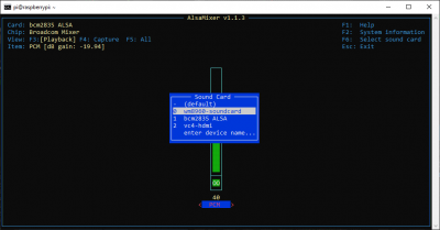
The last part of the installation process requires the default sound card to be configured, using the sudo alsamixer command in the terminal or CLI. From the system menu, use the F6 key to list devices and note the number indicating the WM8960 sound card.
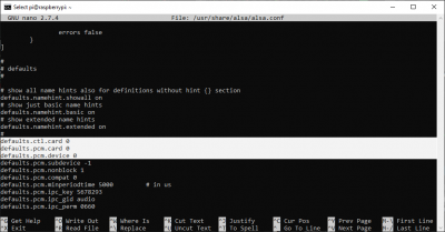
To modify and configure the default sound card, use the sudo nano /usr/share/alsa/alsa.conf command in the terminal or CLI. In the alsa.conf file, users will modify the following lines to the number indicating the WM8960 sound card device value:
language:bash
defaults.ctl.card 0
defaults.pcm.card 0
defaults.pcm.device 0
Note: Users may need to test the values for defaults.pcm.device between with 0 or 1. If they run into the following error:
ALSA lib pcm_dmix.c:1108:(snd_pcm_dmix_open) unable to open peripheral
Traceback (most recent call last):
  File "playwav.py", line 59, in
    device = alsaaudio.PCM(device="default")
alsaaudio.ALSAAudioError: No such file or directory [default]
when running the Python playback code sudo python playwav.py test2.wav in the examples below.
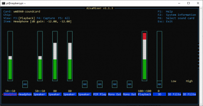
Once these modifications have been made, users should go back an verify that the modifications have taken effect, using the sudo alsamixer command in the terminal or CLI.
Python Examples
In order to use the Python examples provided by Waveshare, users will need to install the libasound2-dev ALSA library and the pyalsaaudio Python package.
- ALSA Library:
sudo apt-get install libasound2-dev - Python Package:
sudo pip3 install pyalsaaudio
Users will need to download example code from the Waveshare website and extract the files:
language:bash
wget https://www.waveshare.com/w/upload/1/19/WM8960_Audio_HAT_Code.tar.gz
tar -xzf WM8960_Audio_HAT_Code.tar.gz
Once extracted, users will need to change the directory into the extracted folder. There they can use the following sample codes to record and play .wav files.
- Record to File:
sudo python3 recordwav.py test2.wav - Play File:
sudo python3 playwav.py test2.wav
Note: Users may run into a type error, when running the Python playback code sudo python playwav.py test2.wav:
Traceback (most recent call last):
  File "playwav.py", line 61, in
    play(device, f)
  File "playwav.py", line 35, in play
    device.setperiodsize(periodsize)
TypeError: integer argument expected, got float
The issue is in line 35 of the playwav.py file, which needs to be modified to periodsize = int(f.getframerate() / 8).
2.4" TFT Display (Linux 5.4 Update)
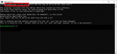
For users who are utilizing the latest distribution of the Raspberry Pi OS with a kernel that has been built after the Linux 5.4 update, the fbtft device has been removed from the available driver modules. The following instructions are the Aug 2020 release (2020-08-20) and later. For prior distribution releases, users should refer to the instructions from Archived section.
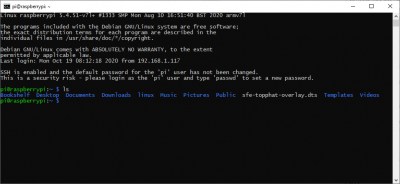
Download the device tree source file sfe-topphat-overlay.dts by clicking on the link or the button below.
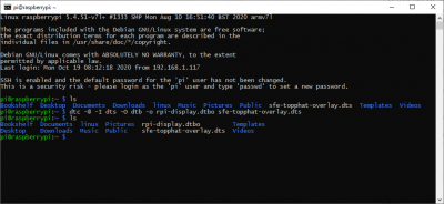
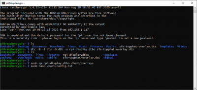
sfe-topphat-overlay.dts file downloaded to the home directory. Compile the overlay file from the download location:
language:bash
dtc -@ -I dts -O dtb -o rpi-display.dtbo sfe-topphat-overlay.dts
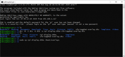
home directory. Copy the compiled file to the device tree overlays directory:
language:bash
sudo cp rpi-display.dtbo /boot/overlays
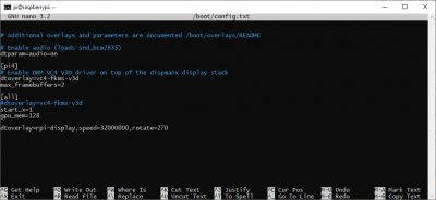
Use your preferred text editor to enable the overlay during boot by adding the following line to the end of the /boot/config.txt file. The example below uses nano with the following command: sudo nano /boot/config.txt.
/boot/config.txt file. Add the following text to the end of the /boot/config.txt file:
dtoverlay=rpi-display,speed=32000000,rotate=270
/boot/config.txt file. Once these changes have been made, reboot the Raspberry Pi with the sudo reboot command for the changes to take effect.
2.4" TFT Display (Archived)
Archived Instructions: The following instructions are only valid for Raspberry Pi OS (or Raspbian) distributions, prior to the Linux 5.4 update. This has been reported to have occurred with the Aug 2020 release (2020-08-20).
There are two steps for the modules required for the 2.4" TFT Screen; adding the driver modules and then a module configuration.
Add Driver Modules
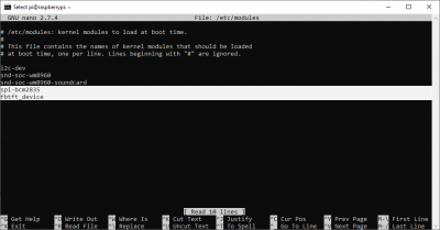
Use your preferred text editor to add the required modules to /etc/modules. The example below uses nano with the following command: sudo nano /etc/modules.
Add the following lines in the file:
spi-bcm2835
fbtft_device
Module Configuration
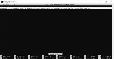
Again, use your preferred text editor to add the required modules to /etc/modprobe.d/fbtft.conf.
Add the following text to the file:
options fbtft_device name=fb_ili9341 gpios=reset:23,dc:24 speed=16000000 bgr=1 rotate=180 custom=1
fbtft module. (Click to enlarge) Once these changes have been made, reboot the Raspberry Pi with the sudo reboot command for the changes to take effect.
Note: Users with the touch screen (from the initial release) should, instead, add the following text to configure the screen properly:
options fbtft_device name=fb_ili9341 gpios=reset:23,dc:24 speed=16000000 bgr=1 rotate=180 custom=1 init=\
-1,0x28,-2,20,-1,0x21,-1,0xCF,0x00,0x83,0x30,-1,0xED,0x64,0x03,0x12,0x81,-1,0xE8,0x85,0x01,0x79,\
-1,0xCB,0x39,0x2c,0x00,0x34,0x02,-1,0xF7,0x20,-1,0xEA,0x00,0x00,-1,0xC0,0x26,-1,0xC1,0x11,\
-1,0xC5,0x35,0x3E,-1,0xC7,0xBE,-1,0xB1,0x00,0x1B,-1,0xB6,0x0a,0x82,0x27,0x00,-1,0xB7,0x07,\
-1,0x3A,0x55,-1,0x36,0x38,-1,0x11,-2,120,-1,0x29,-2,20,-3
For users, unsure about the production model they have, the Top pHAT has separate SKUs. However, the most apparent differences are the screen's colors appear inverted when using the wrong setting; or the chip on the screen's ribbon cable that is utilized for the touch capability.
DEV-16301
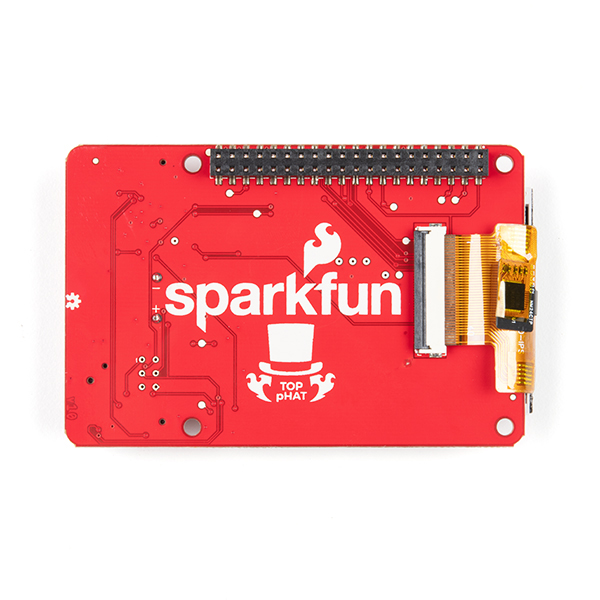
Initial product release with touch screen. The additional chip for the touch capability can be seen on the right, attached to the ribbon cable.
DEV-16653
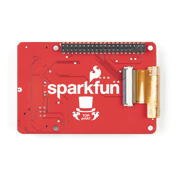 Updated product release without the touch capability; no chip is attached to the ribbon cable. The touch screen was initially used due to supply shortages.
Screen Operation
To utilize the screen, users will call the con2fbmap command. The command is followed by two inputs; the terminal to be displayed and the frame buffer, in that order.
List Frame Buffer
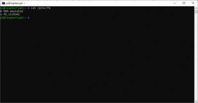
Get the input for the frame buffer, use the cat /proc/fb, it will list what the fb numbers are.
List Users and their Terminals
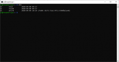
To list the active users and their terminals, the who command can be used.
Examples
Below is are some examples for using the screen. (*Don't forget to reboot the Raspberry Pi for the previous configurations to take effect.)
- Display terminal on the TFT using the
con2fbmap 1 1command in the terminal or CLI. Then exit to the virtual terminal using Ctrl + Alt + F1. - To swap between the display and the HDMI output, use the
startxcommand in the terminal or CLI initiate the PIXEL desktop through the HDMI output. To revert back to the display, click on Raspberry Pi icon -> Shutdown -> Exit to Commandline. - In order to utilize the display on startup, users can modify the
/etc/rc.localfile using thesudo nano /etc/rc.localcommand in the terminal or CLI. Users will need to add thecon2fbmap 1 1command just above theexit 0entry.
OS Configuration: Part 2
Boot to CLI
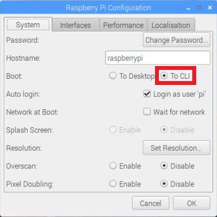
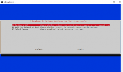
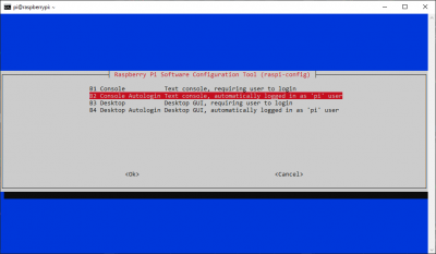
Users will want to configure the OS to boot to the console through the System or Boot Options menus, in order to utilize the screen on power up.
Raspberry Pi Configuration Application
Boot to CLI through the Raspberry Pi Configuration application. Raspi-Config Application
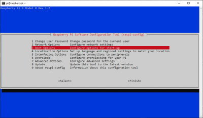
Boot Options menu in the console based raspi-config application. (Click to enlarge) Desktop/CLI menu in the console based raspi-config application. (Click to enlarge) Console Autologin option to configure the system to boot to the CLI. (Click to enlarge) Troubleshooting
For comprehensive information or troubleshooting issues, on the Raspberry Pi, users should check out the Raspberry Pi Foundation website and their forum.
As a general guideline, users should use the following resources when looking for technical information or assistance that is specifically related to the Raspberry Pi itself:
- Raspberry Pi FAQ
- Raspberry Pi Beginner's Subforum
- Raspberry Pi Documentation and Help Guides
- Raspberry Pi Forum
- STICKY - Booting Issues
- See other STICKY topics in the Troubleshooting section of the forum
For users looking for technical assistance, click on the link. There you will find, basic troubleshooting tips and instructions to get started with posting a topic in our forums. Our technical support team will do their best to assist you.
Resources and Going Further
Product Information
- Schematic
- Eagle Files
- GitHub Hardware Repository
- Screen:
- Audio:
- Button:
- LEDs:
Raspberry Pi Resources:
Raspberry Pi Help Guides & Documentation:
Or check out this blog post for ideas.
