SparkFun Satellite Transceiver Kit - Swarm M138 Hookup Guide
 PaulZC
Hardware Overview
Swarm M138 Modem
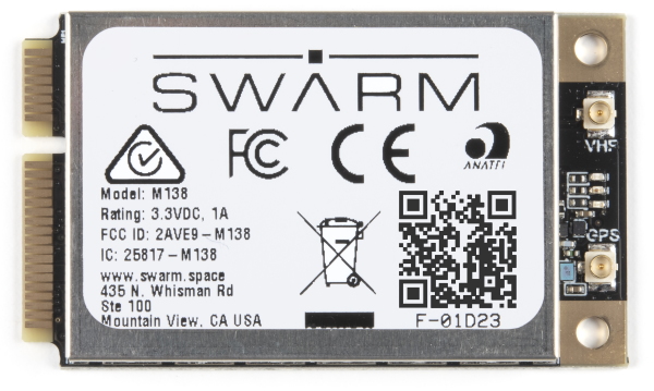
At the heart of our product is a Swarm M138 satellite modem. This is a Mini-PCI Express Card containing both the satellite modem and a very capable u-blox GNSS receiver, all in one integrated package! It can operate from a wide range of supply voltages: 3.0V Min; 5.0V Max. Its standard 3.3V CMOS serial UART interface and NMEA-style command set makes it easy to integrate into your project.
USB-C and CH340
Our board includes a USB-C interface for power and/or serial data, in addition to a full set of breakout pins. Want to plug it into your laptop or Raspberry Pi and use it to communicate out in the field? You can absolutely do that!
We've included our standard CH340E interface chip to convert USB to serial. On Windows, you may need to install a driver and we have a tutorial to help with that:
How to Install CH340 Drivers
We've included a 2A resettable fuse too, just in case anything goes wrong.
mPCIe Connector
 |
 |
|---|---|
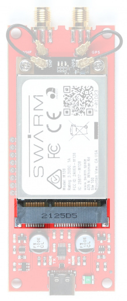
| mPCIe connector | Screw Fixings |
The M138 modem is a very nicely designed piece of kit. The mPCIe card-edge connection makes it really easy to integrate. Two M2.5 screws secure the modem in position.
SMA Connections
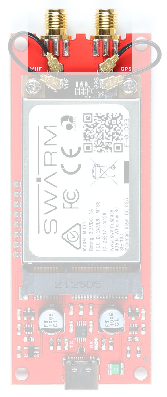
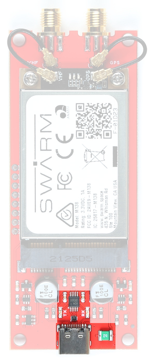
You can connect your antennas straight to the u.FL connectors on the modem itself. However, for a more robust connection, you may want to use the included 25mm u.FL cables to connect the modem to the two threaded SMA connections on the Breakout.
The "VHF" (Very High Frequency) connection is for the Swarm satellite antenna. Don't forget that the Swarm antenna requires a ground plane. There is one included in the box.
The "GPS" connection is for the mandatory GNSS satellite antenna. The modem will not work correctly unless it is aware of its location and the time, which it gets from GNSS. You can use the included Molex adhesive antenna, or you may prefer to use your own active or passive GNSS antenna. The Molex antenna is designed to be stuck to a window or another electrically-transparent surface. If you stick it to a ground plane or another conductive surface, you will not receive a signal. Peeling it off again is difficult, so please think before you stick!
Power Circuitry

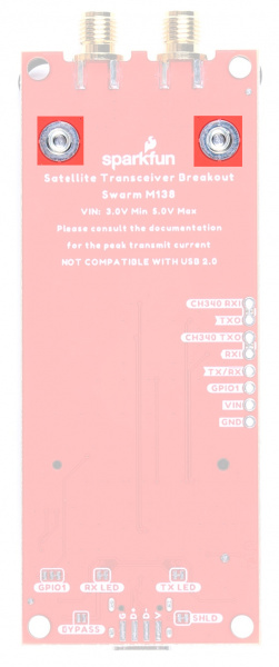
The Breakout includes a dual "ideal diode" power mux circuit, allowing the modem to draw power from the USB connector or the VIN breakout pin with ~zero voltage drop. Two large 100 μF capacitors provide the necessary supply rail decoupling.
Please refer to the schematic for more details.
LEDs
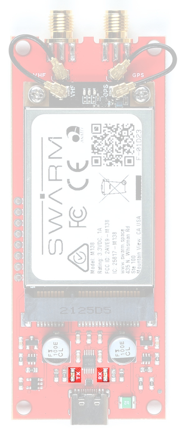
The Breakout has TX and RX LEDs connected to the CH340 signals. These can be disabled if required by cutting the TX and RX jumpers on the bottom of the board.