SparkFun Satellite Transceiver Kit - Swarm M138 Hookup Guide
 PaulZC
Breakout Pins
The table below describes the function of each of the Satellite Transceiver Breakout - Swarm M138 breakout pins:

| Pin Name | Function | Description | Notes |
|---|---|---|---|
| CH340 RXI | Input | CH340 USB Interface: Receive Data In. | Logic level is 3.3V. |
| TXO | Output | Swarm Serial (UART) Interface: Transmit Data Out. | Logic level is 3.3V. By default this pin is linked to CH340 RXI. Open the jumper to isolate. |
| CH340 TXO | Output | CH340 USB Interface: Transmit Data Out. | Logic level is 3.3V. |
| RXI | Input | Swarm Serial (UART) Interface: Receive Data In. | Logic level is 3.3V. By default this pin is linked to CH340 TXO. Open the jumper to isolate. |
| TX/RX | Output | Swarm TX / RX pin. | Logic level is 3.3V. High during TX, low during RX. |
| GPIO1 | I/O (Configurable) | Swarm GPIO1 pin. | Logic level is 3.3V. Can be configured in many different ways. See below for more details. |
| VIN | Power | Power input. | 3.0V Min. 5.0V Max. |
| GND | Power | Power ground / 0V. |
Power can be provided via the USB connector or the VIN pin, or both. The modem will draw power from whichever voltage is higher. The on-board "ideal diode" power mux circuit allows both to be connected simultaneously.
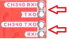
By default:
- Modem TXO is connected to CH340 RXI
- Modem RXI is connected to CH340 TXO
You will need to open the jumper links on the back of the board to use the TXO and RXI pins directly.
You may find it useful to read this tutorial first:
How to Work with Jumper Pads and PCB Traces
GPIO1
GPIO1 is a multi-function input/output pin. It can be configured into different modes via the GP command:
| Mode | Description |
|---|---|
| 0 | Analog, pin is internally disconnected and not used (default) |
| 1 | Analog ADC, pin can be read to measure input voltage (0-3.3V) |
| 2 | Input, pin can be read as a general purpose digital input (High or Low) |
| 3 | Input, low-to-high transition exits sleep mode |
| 4 | Input, high-to-low transition exits sleep mode |
| 5 | Output (Open Drain), set low as a general purpose digital output |
| 6 | Output (Open Drain), set high as a general purpose digital output |
| 7 | Output (Open Drain), low indicates unread messages pending for user |
| 8 | Output (Open Drain), high indicates unread messages pending for user |
| 9 | Output (Open Drain), low indicates unsent messages pending for transmit |
| 10 | Output (Open Drain), high indicates unsent messages pending for transmit |
| 11 | Output (Open Drain), low indicates unread or unsent messages |
| 12 | Output (Open Drain), high indicates unread or unsent messages |
| 13 | Output (Open Drain), low indicates sleep mode is active. Otherwise output is high |
| 14 | Output (Open Drain), high indicates sleep mode is active. Otherwise output is low |
We've included both pull-up and pull-down resistors for GPIO1, configurable via a dual split pad jumper. By default, GPIO1 is pulled up to 3.3V so that the open drain output modes generate the correct logic level output. You can remove the pull-up by changing the jumper:
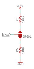
GPIO1 can sink a maximum of 8mA.
TX/RX
TX/RX is a push-pull output which is: high (3.3V) when the modem is transmitting; low (0V) when the modem is receiving or idle.