SparkFun Qwiic 3-Axis Accelerometer (ADXL313) Hookup Guide
 QCPete
 Introduction
The SparkFun 3-Axis Digital Accelerometer Breakout - ADXL313 (Qwiic) is a Qwiic sensor that utilizes the ADXL313 accelerometer from Analog Devices. The ADXL313 is a low cost, low power, up to 13-bit resolution, 3-axis accelerometer with a 32-level FIFO stack capable of measuring up to ±4g.
The ADXL313 can be used in applications like car alarms, hill start aid (HSA) systems, electronic parking brakes, and (black box) data recorders. Some of the specific features of the ADXL313 include:
- Embedded, patent pending FIFO technology minimizes host processor load
- Low noise performance
- Fixed 10-bit resolution for any g-range
- 10,000g survival rating
- Two configurable interrupt pins
- Including, built-in motion detection functions for activity/inactivity monitoring
- Self-test capability
Required Materials
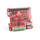
The Qwiic 3-Axis Accelerometer does need a few additional items for you to get started. The RedBoard Qwiic will be used for the Arduino examples. A single board computer and the Qwiic pHAT are required for the Python examples (see note below). You may already have a few of these items, including the required Qwiic cable, so feel free to modify your cart based on your needs. Additionally, there are also alternative parts options that are available as well (click button below to toggle options).


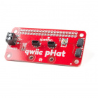


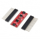
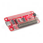
SparkFun Top pHAT for Raspberry Pi
DEV-16301
Qwiic Cable - 50mm
PRT-14426
Qwiic Cable - 100mm
PRT-14427
Qwiic Cable - 200mm
PRT-14428
Qwiic Cable - 500mm
PRT-14429
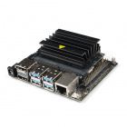
NVIDIA Jetson Nano Developer Kit (V3)
DEV-16271
pi-topCEED (Green)
KIT-14035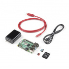
SparkFun Raspberry Pi 4 Basic Kit - 8GB
KIT-16831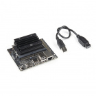
NVIDIA Jetson Nano 2GB Developer Kit
DEV-17244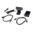
SparkFun DLI Kit for Jetson Nano 2GB
KIT-17245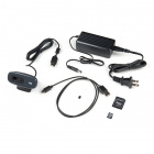
SparkFun DLI Kit (without Jetson Nano)
KIT-16389Suggested Reading
If you're unfamiliar with serial terminals, jumper pads, or I2C be sure to checkout some of these foundational tutorials.
Installing an Arduino Library
Logic Levels
I2C
Serial Terminal Basics
How to Work with Jumper Pads and PCB Traces
RedBoard Qwiic Hookup Guide
Qwiic pHAT for Raspberry Pi Hookup Guide
Arduino Shields v2
Raspberry Pi SPI and I2C Tutorial
Python Programming Tutorial: Getting Started with the Raspberry Pi
Working with Qwiic on a Jetson Nano through Jupyter Notebooks
The Qwiic ADXL313 Accelerometer utilizes the Qwiic connect system. We recommend familiarizing yourself with the Logic Levels and I2C tutorials (above) before using it. Click on the banner above to learn more about our Qwiic products.
Note: First time Raspberry Pi users should also head over to the Raspberry Pi Foundation website and check out their quickstart guides:
- Blog Post: Getting started with your Raspberry Pi
- Raspberry Pi Foundation Getting Stared Guides:
- MagPi Books and Guides:
- Article: Get started with your new Raspberry Pi
- The Offical Raspberry Pi Beginner’s Book (December 2017)
- Get Started with Raspberry Pi (November 2019)
- The Offical Raspberry Pi Beginner’s Guide: How to use your new computer
1st Edition (December 2018)
2nd Edition (June 2019)
3rd Edition (November 2019)
We have also listed a few additional resources for users to familiarize themselves with the Raspberry Pi:
Note: First time Nvidia Jetson Nano users should also head over to the Nvidia website and check out their guides and tutorials:
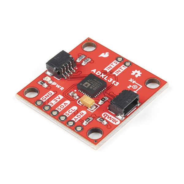
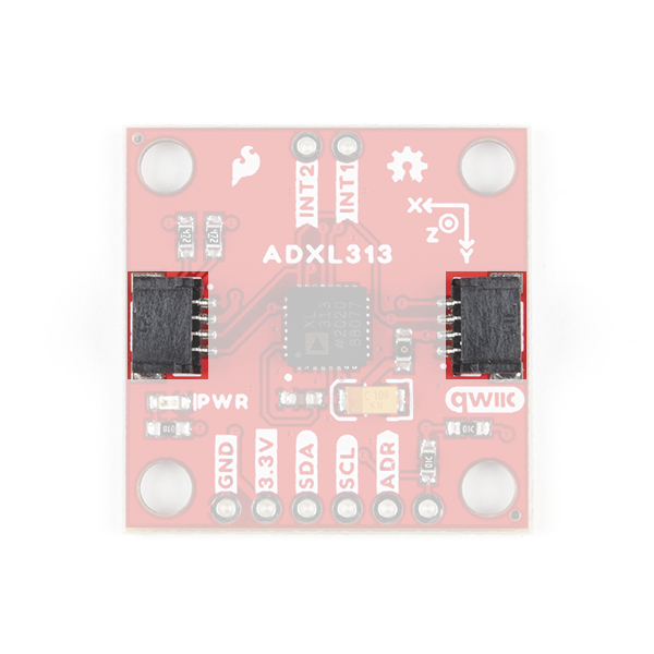
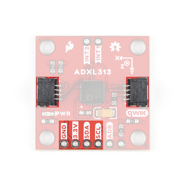
Hardware Overview
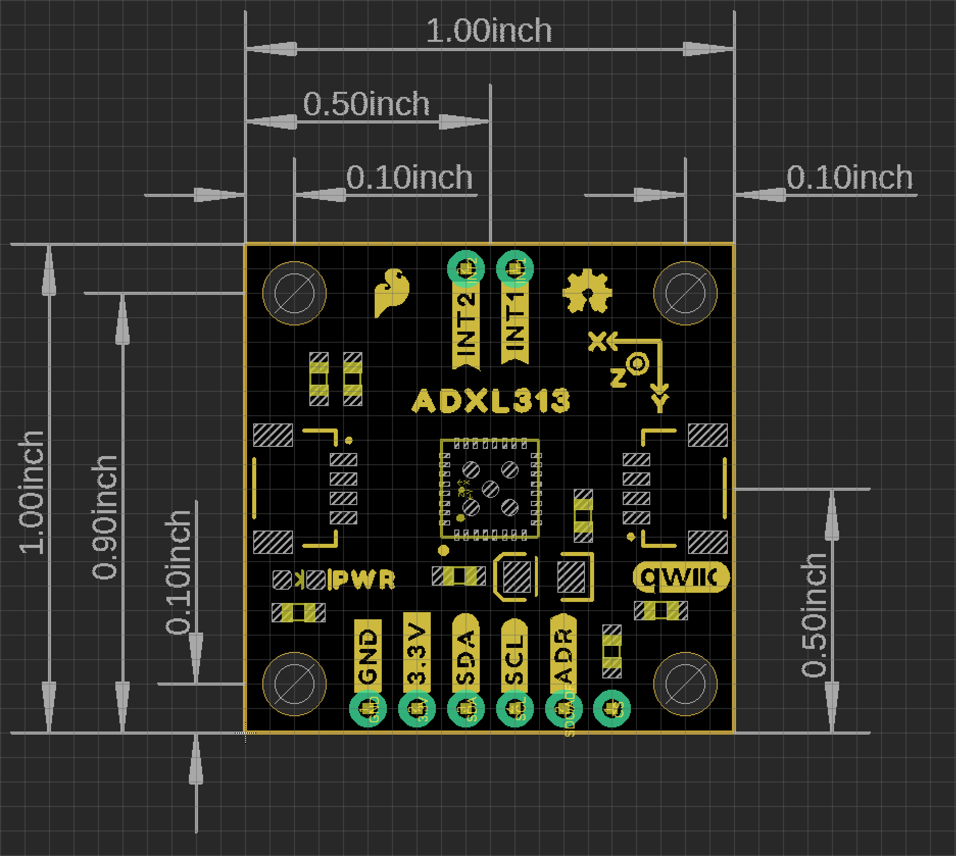
Board Dimensions
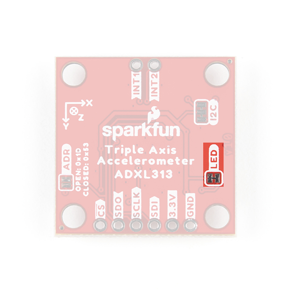
The SparkFun 3-Axis Digital Accelerometer Breakout - ADXL313 (Qwiic) is laid out on the standardized 1" x 1" (2.54 x 2.54 cm) Qwiic breakout board and includes the standard four 0.13" mounting holes, which are compatible with 4-40 screws.
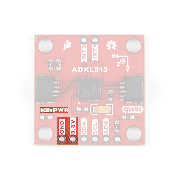
Power
There is a power status LED to help make sure that your Qwiic ADXL313 Accelerometer is getting power. You can power the board either through the polarized Qwiic connector system or the breakout pins (3.3V and GND) provided. The Qwiic system is meant to run on 3.3V, be sure that you are NOT using another voltage when using the Qwiic system. A jumper is available on the back of the board to remove power to the LED for low-power applications (see Jumpers section below).
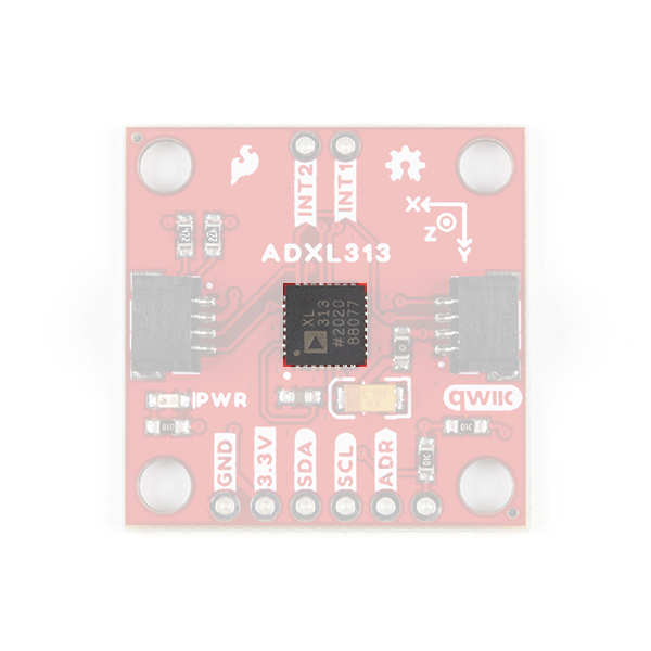
ADXL313 Accelerometer
The ADXL313 accelerometer from Analog Devices is a low cost, low power, up to 13-bit resolution, 3-axis accelerometer with a 32-level FIFO stack capable of measuring up to ±4g. The shock rating for the sensor (IC only, not board) is up to 10,000g, which is great for data loggers like black boxes. The sensor also has automotive applications including car alarms, hill start aid (HSA) systems, and electronic parking brakes.
Theory of Operation
The sensor mechanism contains a polysilicon structure built above a silicon wafer. The polysilicon structure includes a central mass with springs to suspend it over the surface of the wafer. An acceleration creates a deflection of the structure, which is measured with differential capacitors, resulting in a sensor output whose amplitude is proportional to acceleration. Phase-sensitive demodulation is used to determine the magnitude and polarity of the acceleration.
For more details, check out these articles from Analog Devices:
- Dual Axis, Low g, Fully Integrated Accelerometers
- Sonic Nirvana: Using MEMS Accelerometers as Acoustic Pickups in Musical Instruments
Sensor Characteristics
Below, is a table of the characteristics of the accelerometer. For more details, please refer to the datasheet.
| Characteristic | Description |
|---|---|
| Power |
Supply Voltage: 2.0 - 3.6V Supply Cuurent:
|
| Measurement Range | ±.5g, ±1g, ±2g, ±4g |
| Resolution |
All Ranges: 10 bits (Default) ±.5g Range: 10 bits (Full Resolution) ±1g Range: 11 bits (Full Resolution) ±2g Range: 12 bits (Full Resolution) ±4g Range: 13 bits (Full Resolution) |
| FIFO Stack | 32 levels |
| Data Rate | 6.25 - 3200Hz |
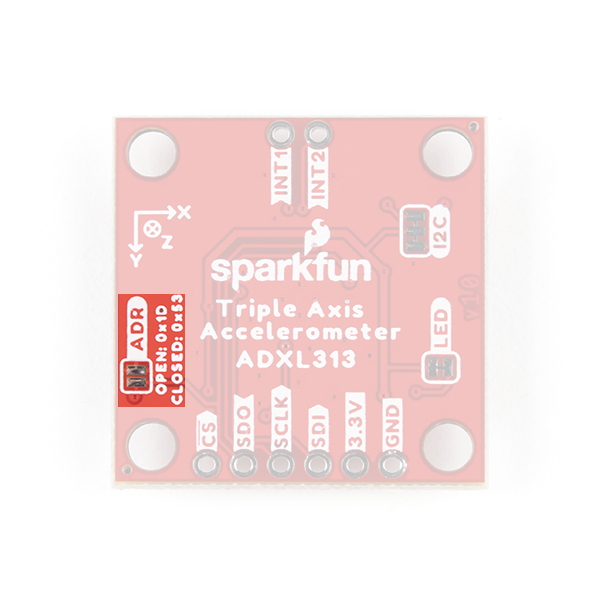
| I2C Address (7-bit) | 0x1D (Default), 0x53 |
| SPI Configuration | 3-wire or 4-wire Operation |
Power Modes
By default, with standard operation, the ADXL313 automatically modulates its power consumption based on the output data rate. For increased power savings, an optional low power mode is available for data rates below 400 Hz. The available power savings for the low power mode (VS = 3.3V) is detailed in the table below. In addition, there are two power configurations for minimal power consumption. For more details, please refer to the datasheet.
| Output Data Rate (Hz) | Bandwidth (Hz) | Current Consumption (at VS = 3.3V): IDD (µA) | |
|---|---|---|---|
| Std. Operation | Low Power Mode | ||
| 3200 | 1600 | 170 | --- |
| 1600 | 800 | 115 | --- |
| 800 | 400 | 170 | --- |
| 400 | 200 | 170 | 115 |
| 200 | 100 | 170 | 82 |
| 100 | 50 | 170 | 65 |
| 50 | 25 | 115 | 57 |
| 25 | 12.5 | 82 | 50 |
| 12.5 | 6.25 | 65 | 43 |
| 6.25 | 3.125 | 57 | --- |
Autosleep Mode
Autosleep mode provides additional power savings by automatically switching the ADXl313 into sleep mode during periods of inactivity. The inactivity level is determined by two factors, a threshold value and a time period. Based upon their configuration, if the sensor doesn't detect an acceleration in excess of the threshold value for the specified time period, the ADXL313 will automatically transition into sleep mode.
Standby Mode
Placing the ADXL313 into standby mode discontinues any measurements, preserves the contents of the FIFO stack, and reduces current consumption down to 0.1 µA.
FIFO Operation
The ADXL313 includes a 32-level FIFO stack management system that is utilized to minimize the burden on the host microcontroller. The buffer has four different modes of operation: Bypass, FIFO, Stream, and Trigger. For more details, please refer to the datasheet.
Note: For users unfamiliar with how a FIFO typically operates, check out this example from the Qwiic Keypad hookup guide.
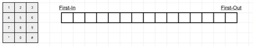
Demonstration of the FIFO: (1) Filling the FIFO stack with inputs, (2) overwriting old inputs, and (3) incrementing & reading the FIFO.
Bypass Mode
The FIFO is bypassed and no values are stored.
FIFO Mode
The FIFO collects up to 32 values and then stops collecting data and triggers the watermark interrupt, collecting new data only when FIFO is not full. The accelerometer will continue to operate after the FIFO is full, so that features such as activity detection can still be utilized. The watermark interrupt will continue to trigger until the number of samples in FIFO is less than the threshold.
Stream Mode
The FIFO holds the latest 32 data values. When FIFO is full, the oldest data is overwritten with newer data and the watermark interrupt will trigger. The watermark interrupt will continue to trigger until the number of samples in FIFO is less than the threshold.
Trigger Mode
When triggered by the trigger bit, FIFO holds the last data samples before the trigger event and then continues to collect data until full. New data is collected only when FIFO is not full. Additional trigger events will not function in this mode until the trigger mode is cleared.
Self Test Operation
A unique feature of the ADXL313 is the self test operation, which can test the sensor's mechanical and electronic systems simultaneously. When enabled, an electrostatic force is exerted on the mechanical sensor and moves the mechanical sensing element in the same manner as an acceleration would. This creates an additive acceleration that is proportional to VS2. For more details, please refer to the datasheet.
Qwiic and I2C
I2C Address
The Qwiic ADXL313 Accelerometer’s I2C address, 0x1D (7-bit), is factory set. An alternate I2C address of 0x53 (7-bit) can be configured by modifying the ADDR jumper or by pulling the ADR pin low.
Qwiic Connectors
The simplest way to use the Qwiic ADXL313 Accelerometer is through the Qwiic connect system. The connectors are polarized for the I2C connection and power. (*They are tied to the corresponding power and I2C breakout pins.)
Breakout Pins
The board also provides eight labeled breakout pins.

I2C
You can connect these lines to the I2C bus of your microcontroller and power pins (3.3V and GND), if it doesn't have a Qwiic connector. The interrupt pins are also broken out to use for triggered events.
SPI
You can connect these lines to the SPI bus of your microcontroller and power pins (3.3V and GND); the sensor can operate in either a 3-wire or 4-wire configuration. The interrupt pins are also broken out to use for triggered events.
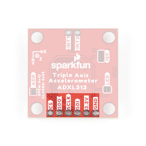
Interrupt Pins
The interrupt pins (active high) are used to indicate various states of the ADXL313, depending on how they are configured and if they are enabled. The interrupt pins can be configured for the following modes:
- Activity - Triggers when the acceleration is greater than a stored threshold.
- Inactivity - Triggers when the acceleration is lower than a store threshold for a specified amount of time (up to 255 seconds).
- Watermark - Triggers when the number of samples stored in the FIFO reaches a specific value.
- Overrun - Triggers when the FIFO is overrun (new data replaces unread data in the stack).
Additionally, the interrupts can be used to trigger measurements into the FIFO, when the FIFO is configured for Trigger Mode.

Jumpers
There are three jumpers on the board. Not sure how to cut or modify a jumper? Read here!
Power LED
Cutting the LED jumper will remove the 1kΩ resistors and PWR LED from the 3.3V power. This is useful for low power applications.
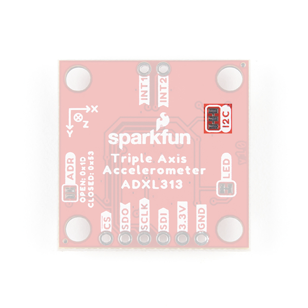
I2C Pull-Up
Cutting the I2C jumper will remove the 4.7kΩ pull-up resistors from the I2C bus. If you have many devices on your I2C bus you may want to remove these jumpers.
Address Pull-up
Soldering the ADR jumper connect a 10kΩ pull-up resistor to the SDO/ADR pin. This can be used to configure the default I2C address of the device to 0x53 (7-bit) on power up.
Hardware Assembly
Arduino Examples
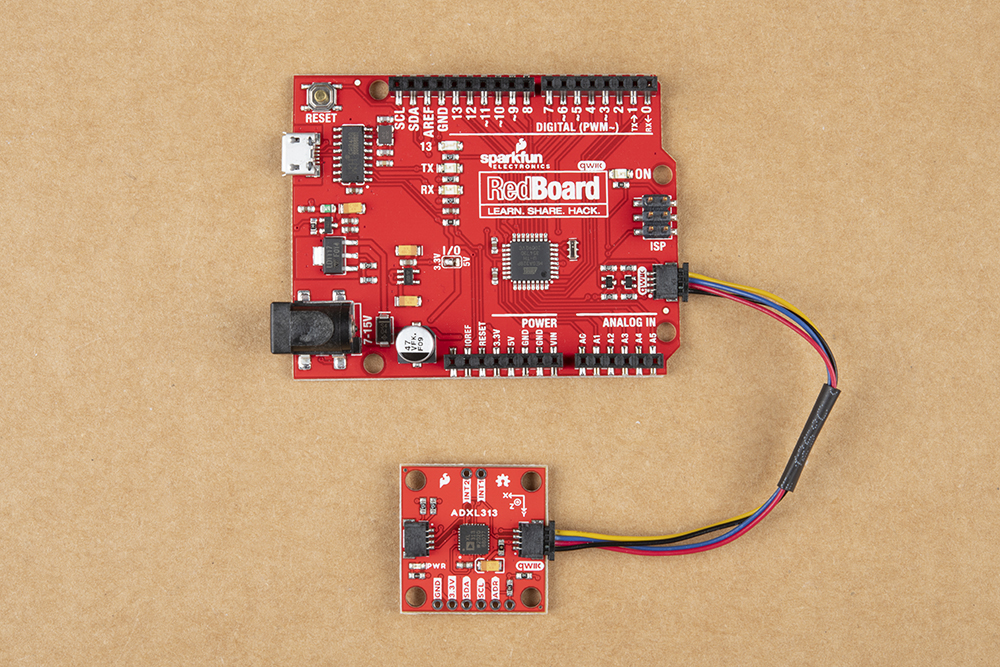
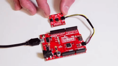
With the Qwiic connector system, assembling the hardware is simple. All you need to do is connect your SparkFun 3-Axis Digital Accelerometer Breakout - ADXL313 (Qwiic) to the RedBoard Qwiic with a Qwiic cable. Otherwise, you can use the I2C pins of your microcontroller; just be aware of logic levels.
Note: This tutorial assumes users are familiar with Arduino products and are using the latest stable version of the Arduino IDE on your desktop. If this is your first time using the Arduino IDE, please review our tutorial on installing the Arduino IDE.
Python Examples
With the Qwiic connector system, assembling the hardware is simple. In addition to the SparkFun 3-Axis Digital Accelerometer Breakout - ADXL313 (Qwiic), you will need: a Qwiic cable, a SparkFun Qwiic pHAT for Raspberry Pi, single board computer, monitor, and standard peripherals. (*If you are unfamiliar with the Qwiic pHAT, you can find the Hookup Guide here.)
There are two single board computer (SBC) options that we have tested on:
- Raspberry Pi setup with the Raspbian OS
- Jetson Nano running Nvidia's L4T image
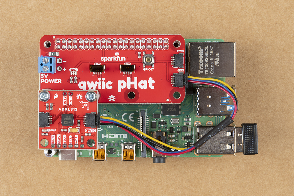
Raspberry Pi 4 (with Qwiic pHAT) connected the Qwiic ADXL313 Accelerometer.
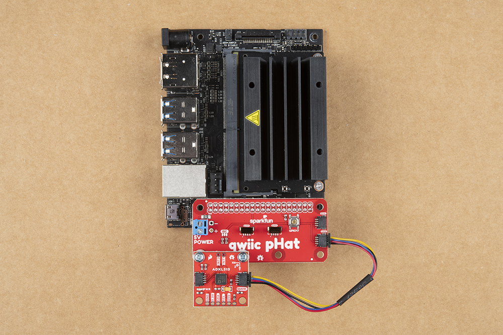 Jetson connected to the Qwiic ADXL313 Accelerometer.
Note: Don't forget to connect any necessary peripherals, such as a monitor, keyboard and mouse, and power supply to the single board computer.
Note: This tutorial assumes users are familiar with using a Raspberry Pi and have the latest version of Raspbian OS (full... with recommended software) your Raspberry Pi. You can download the latest version of the Raspbian OS from the Raspberry Pi Foundation website.
If this is your first time using a Raspberry Pi, please head over to the Raspberry Pi Foundation website to use their quickstart guides. We have listed a few of them here:
Note: This tutorial assumes users are familiar with using a Jetson Nano and you have the latest version of L4T OS your Jetson Nano. You can download the latest version of the L4T OS from the Jetson Download Center on Nvidia's website.
If this is your first time using a Jetson Nano, please head over to the Nvidia website to use their quickstart guides. We have listed a few of them here:
Arduino Library
Note: This example assumes you are using the latest version of the Arduino IDE on your desktop. If this is your first time using Arduino, please review our tutorial on installing the Arduino IDE. If you have not previously installed an Arduino library, please check out our installation guide.
We've written a library to easily get setup and take readings from the SparkFun 3-Axis Digital Accelerometer Breakout - ADXL313 (Qwiic). However, before we jump into getting data from the sensor, let's take a closer look at the available functions in the library. You can install this library through the Arduino Library Manager. Search for SparkFun ADXL313 Arduino Library and you should be able to install the latest version. If you prefer manually downloading the libraries from the GitHub repository, you can grab them here:
Let's get started by looking at the functions that set up the ADXL313:
Class
In the global scope, construct your sensor object (such as mySensor) without arguments.
ADXL313 mySensor;
Object Parameters and setup()
Rather than passing a bunch of data to the constructor, configuration is accomplished by setting the values of the ADXL313 type in the setup() function. They are exposed by being public: so use the myName.aVariable = someValue; syntax.
- Initialize Sensor
- .begin() or .begin(i2caddr, Wire) - Initializes the sensor with basic settings and returns false if sensor is not detected.
- .isConnected() - Returns true if I2C device ack's
- .beginSPI(CS_pin) - Initializes the sensor with basic settings via SPI and returns false if sensor is not detected.
- .checkPartId() - Returns true if device's part ID register is correct.
- .dataReady() - Checks the
dataReadybit - .updateIntSourceStatuses()
- .standby() - Clears the measure bit, putting decive in standby mode, ready for configuration
- .measureModeOn() - Sets the measure bit, putting decive in measure mode, ready for reading data
- .softReset() - Soft reset clears all settings, and puts it in standby mode
- .printAllRegister() - Print Register Values to Serial Output.
- Can be used to Manually Check the Current Configuration of Device
- .begin() or .begin(i2caddr, Wire) - Initializes the sensor with basic settings and returns false if sensor is not detected.
- Reading Acceleration
- .readAccel() - Reads acceleration data from ADXL313 into three class variables: x, y, and z.
- Sensor Configuration
- Range Setting
- .setRange(range)
- 0.5g, 1g, 2g, or 4g
- .getRange()
- .setRange(range)
- Autosleep Bit
- .autosleepOn() - Sets the autosleep bit
- Note, prior to calling this, you will need to set
THRESH_INACTandTIME_INACT.
- Note, prior to calling this, you will need to set
- .autosleepOff() - Clears the autosleep bit
- .autosleepOn() - Sets the autosleep bit
- Self-Test Bit
- .setSelfTestBit(selfTestBit)
1- Self-Test Applied. Electrostatic Force exerted on the sensor causing a shift in the output data.0- Self-Test Disabled.
- .getSelfTestBit()
- .setSelfTestBit(selfTestBit)
SPIBit State- .setSpiBit(spiBit)
1- Puts Device in 3-wire Mode0- Puts Device in 4-wire SPI Mode
- .getSpiBit()
- .setSpiBit(spiBit)
INT_INVERTBit State- .setInterruptLevelBit(interruptLevelBit)
0- Sets the Interrupts to Active HIGH1- Sets the Interrupts to Active LOW
- .getInterruptLevelBit()
- .setInterruptLevelBit(interruptLevelBit)
FULL_RESBit State- .setFullResBit(fullResBit)
1- Device is in Full Resolution Mode: Output Resolution Increase with G Range set by the Range Bits to Maintain a 4mg/LSB Scale Factor0- Device is in 10-bit Mode: Range Bits Determine Maximum G Range and Scale Factor
- .getFullResBit()
- .setFullResBit(fullResBit)
JUSTIFYBit State- .setJustifyBit(justifyBit)
1- Selects the Left Justified Mode0- Selects Right Justified Mode with Sign Extension
- .getJustifyBit()
- .setJustifyBit(justifyBit)
- Gain -Gains for each axis in g's/count
- .setAxisGains(_gains)
- .getAxisGains(_gains)
OFSX,OFSY, andOFSZBytes - User Offset Adjustments in Twos Complement Format. Scale Factor of 15.6mg/LSB.- .setAxisOffset(x, y, z)
- .getAxisOffset(x, y, z)
THRESH_ACTRegister - Holds the Threshold Value for Detecting Activity.- .setActivityThreshold(activityThreshold)
- Data Format is Unsigned, so the Magnitude of the Activity Event is compared with the Value is Compared with the Value in the
THRESH_ACTRegister. - The Scale Factor is 62.5mg/LSB.
- Value of 0 may Result in Undesirable Behavior if the Activity Interrupt Enabled.
- It Accepts a Maximum Value of 255.
- Data Format is Unsigned, so the Magnitude of the Activity Event is compared with the Value is Compared with the Value in the
- .getActivityThreshold() - Gets the THRESH_ACT byte
- .setActivityThreshold(activityThreshold)
THRESH_INACTRegister - Holds the Threshold Value for Detecting Inactivity.- .setInactivityThreshold(inactivityThreshold)
- The Data Format is Unsigned, so the Magnitude of the Inactivity Event is compared with the value in the
THRESH_INACTRegister. - Scale Factor is 62.5mg/LSB.
- Value of 0 May Result in Undesirable Behavior if the Inactivity Interrupt Enabled.
- It Accepts a Maximum Value of 255.
- The Data Format is Unsigned, so the Magnitude of the Inactivity Event is compared with the value in the
- .getInactivityThreshold()
- .setInactivityThreshold(inactivityThreshold)
TIME_INACTRegister- .setTimeInactivity(timeInactivity)
- Contains an Unsigned Time Value Representing the Amount of Time that Acceleration must be Less Than the Value in the
THRESH_INACTRegister for Inactivity to be Declared. - Uses Filtered Output Data unlike other Interrupt Functions
- Scale Factor is 1sec/LSB.
- Value Must Be Between 0 and 255.
- Contains an Unsigned Time Value Representing the Amount of Time that Acceleration must be Less Than the Value in the
- .getTimeInactivity()
- .setTimeInactivity(timeInactivity)
- Range Setting
- Activity Bits
- Enabled
- .isActivityXEnabled()
- .isActivityYEnabled()
- .isActivityZEnabled()
- .isInactivityXEnabled()
- .isInactivityYEnabled()
- .isInactivityZEnabled()
- State
- .setActivityX(state)
- .setActivityY(state)
- .setActivityZ(state)
- .setActivityXYZ(stateX, stateY, stateZ)
- .setInactivityX(state)
- .setInactivityY(state)
- .setInactivityZ(state)
- .setInactivityXYZ(stateX, stateY, stateZ)
- Active
- .isActivityAc()
- .isInactivityAc()
- .setActivityAc(state)
- .setInactivityAc(state)
- Enabled
- Low Power Bit
- .isLowPower()
- .lowPowerOn()
- .lowPowerOff()
- Rate Bits
- .getRate()
- .setRate(rate)
- Bandwidth
- .setBandwidth(bw)
- .getBandwidth()
- Trigger Check - Check if Action was Triggered in Interrupts
- .triggered(interrupts, mask)
- .getInterruptSource()
- .getInterruptSource(interruptBit)
- .getInterruptMapping(interruptBit)
- Interrupt Mapping - Set the Mapping of an Interrupt to
pin1orpin2- .setInterruptMapping(interruptBit, interruptPin)
- .isInterruptEnabled(interruptBit)
- .setInterrupt(interruptBit, state)
- .ActivityINT(status)
- .InactivityINT(status)
- .DataReadyINT(status)
- .WatermarkINT(status)
- .OverrunINT(status)
- FIFO Mode Setting
- .getFifoMode()
- .setFifoMode(mode)
- .getFifoSamplesThreshhold()
- .setFifoSamplesThreshhold(samples)
- .getFifoEntriesAmount()
- .clearFifo()
Arduino Examples
Example 1: Basic Readings
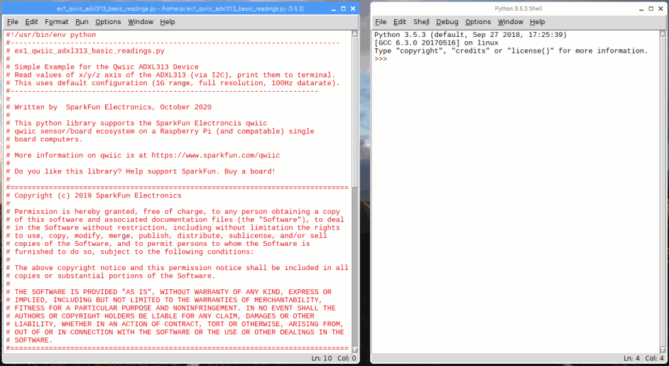
Once you've got the library installed, open the Example1 Basic Readings sketch. You can find it under
File > Examples > SparkFun ADXL313 Arduino Library > Examples
Then load it onto your RedBoard or Uno. Open your favorite Serial Terminal to see the printed values.
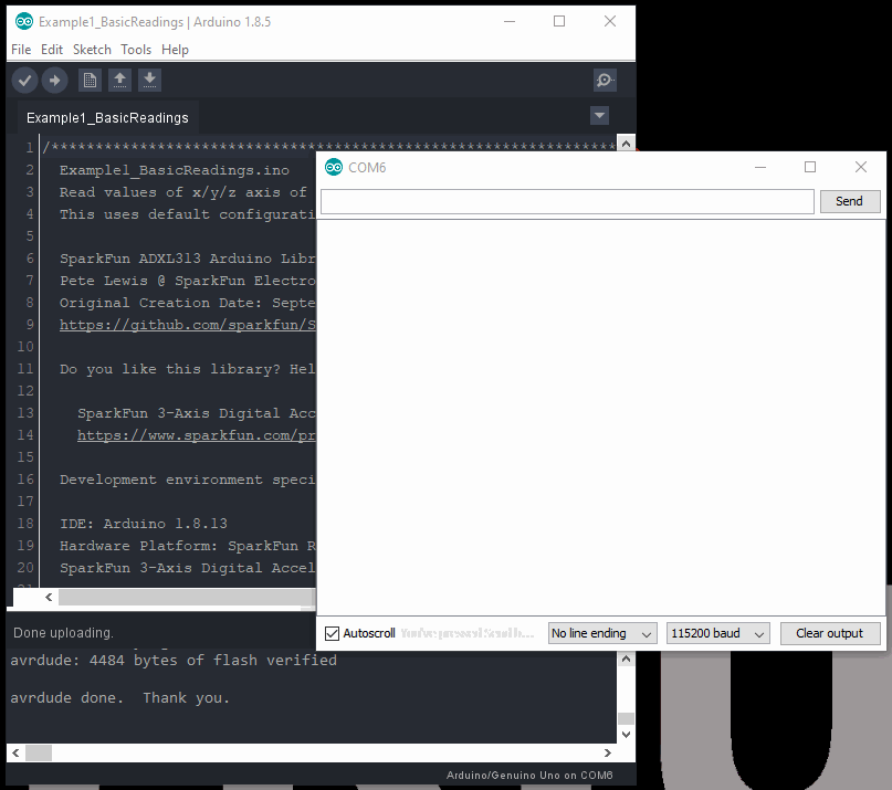
This example outputs the raw acceleration values read by the sensor. To convert the values, use the following equation.
In this example, g-range = 2 and the resolution = 10-bits = 1024; therefore the measured acceleration (g's):
Example 3: Auto. Sleep
Open the Example3 Autosleep sketch, and load it onto your RedBoard or Uno.
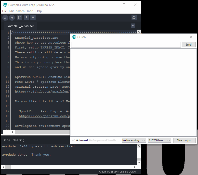
After the sensor detects inactivity for more than 5 seconds, it will automatically enter sleep mode and stop recording data into the FIFO. This conserves power to the accelerometer.
Note: The senor has to be relatively flat on the x-axis in order for it to enter sleep mode. Therefore, users may need to play with a level if their desk isn't level or flat.
Otherwise, users can change the threshold on line 73: myAdxl.setActivityThreshold(10); // 0-255 (62.5mg/LSB) to a higher value, like `40` to increase the inactivity threshold. This means the sensor doesn't have to lie precisely flat, but also means that the sensor requires more acceleration to wake up as well.
Example 6: Interrupt
Note: For this example to work, the microcontroller's interrupt pin needs to be connected to the Qwiic ADXL313. Make sure that this pin is also designated in the code. For the RedBoard Qwiic, Pin 2 can operate as an interrupt and is coded by default in the example.
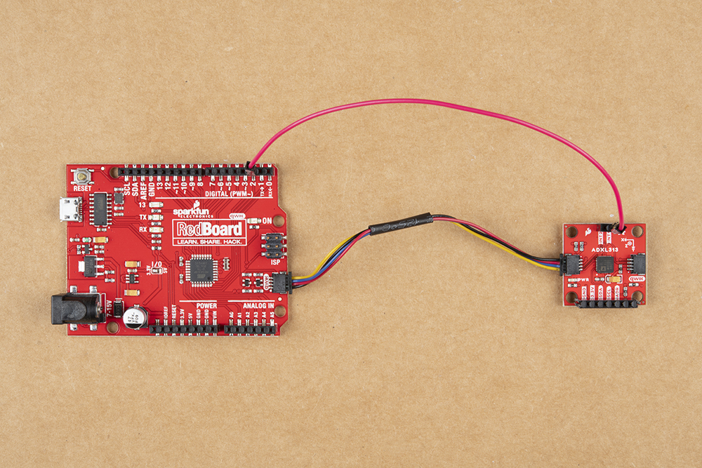
Wiring between ADXL313 and microcontroller for the interrupt functionality. (Click to enlarge)
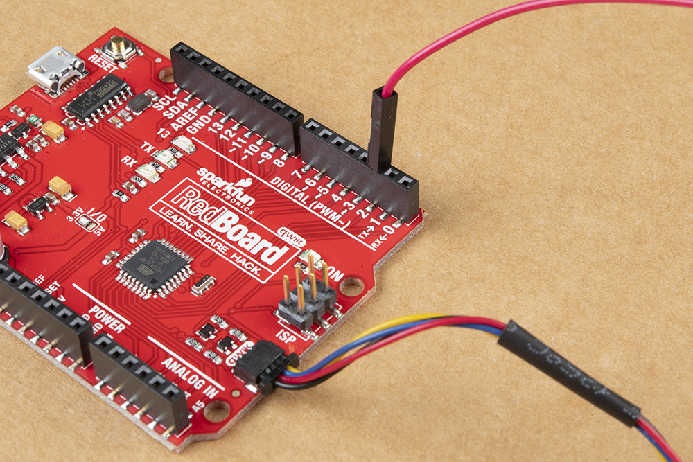
Close up of the wiring at the microcontroller. (Click to enlarge)
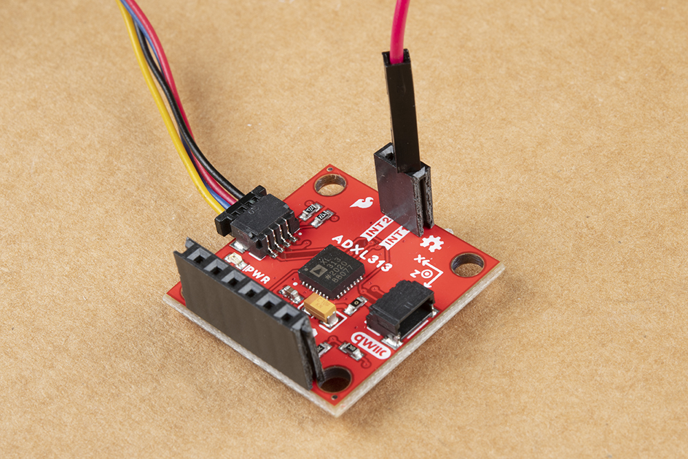
Close up of the wiring at the ADXL313 interrupt pin. (Click to enlarge)
Once the interrupt pin has been wired up, open the Example6 Interrupt sketch, and load it onto your RedBoard or Uno.
Let the sensor sit still, flat on a table to enter sleep mode. While, shaking the accelerometer will trigger the interrupt on the microcontroller for start reading data. Lying the accelerometer flat and still, will discontinue the sensor readings and put it into sleep mode again.
Python Package
Note: This tutorial assumes you are using the latest version of Python 3. If this is your first time using Python or I2C hardware on a Raspberry Pi, please checkout our tutorial on Python Programming with the Raspberry Pi and the Raspberry Pi SPI and I2C Tutorial. Jetson Nano users can check out this tutorial on Working with Qwiic on a Jetson Nano through Jupyter Notebooks.
We've written a Python package to easily get setup and take readings from the ADXL313 accelerometer. There are two methods for installing the Python package for the ADXl313.
- Install the all inclusive SparkFun Qwiic Python package.
- Independently install the SparkFun ADXL313 Python package.
The all inclusive SparkFun Qwiic Python package, is recommended as is also installs the required I2C driver as well.
Note: Don't forget to double check that the hardware I2C connection is enabled on your single board computer.
SparkFun Qwiic Package
This repository is hosted on PyPi as the sparkfun-qwiic package. On systems that support PyPi installation via pip3 (use pip for Python 2) is simple, using the following commands:
For all users (note: the user must have sudo privileges):
language:bash
sudo pip3 install sparkfun-qwiic
For the current user:
language:bash
pip3 install sparkfun-qwiic
Independent Installation
You can install the sparkfun-qwiic-adxl313 Python package independently, which is hosted by PyPi. However, if you prefer to manually download and install the package from the GitHub repository, you can grab them here (*Please be aware of any package dependencies. You can also check out the repository documentation page, hosted on ReadtheDocs.):
PyPi Installation
This repository is hosted on PyPi as the sparkfun-qwiic-adxl313 package. On systems that support PyPi installation via pip3 (use pip for Python 2) is simple, using the following commands:
For all users (note: the user must have sudo privileges):
language:bash
sudo pip3 install sparkfun-qwiic-adxl313
For the current user:
language:bash
pip3 install sparkfun-qwiic-adxl313
Local Installation
To install, make sure the setuptools package is installed on the system.
Direct installation at the command line (use python for Python 2):
language:bash
python3 setup.py install
To build a package for use with pip3:
language:bash
python3 setup.py sdist
A package file is built and placed in a subdirectory called dist. This package file can be installed using pip3.
language:bash
cd dist
pip3 install sparkfun_qwic_adxl313-<version>.tar.gz
Python Package Operation
Before we jump into getting readings, let's take a closer look at the available functions in the Python package. Below, is a description of the basic functionality of the Python package. This includes the package organization, built-in methods, and their inputs and/or outputs. For more details on how the Python package works, check out the source code and package documentation.
Dependencies
This Python package has a very few dependencies in the code, listed below:
language:python
import qwiic_i2c
import time
Default Variables
The default variables, in the code, for this Python package are listed below:
language:python
# qwiic_adxl313 GLOBAL VARIABLES
#----------------------------------------------------------------------------------------------------
# Define the device name and I2C addresses. These are set in the class defintion
# as class variables, making them avilable without having to create a class instance.
# This allows higher level logic to rapidly create a index of qwiic devices at
# runtine
#
# The name of this device
_DEFAULT_NAME = "Qwiic ADXL313"

# Some devices have multiple availabele addresses - this is a list of these addresses.
# NOTE: The first address in this list is considered the default I2C address for the
# device.
_AVAILABLE_I2C_ADDRESS = [0x53, 0x1D]

# define our valid chip IDs
_validChipIDs = [0xCB]
language:python
# QwiicAdxl313 CLASS VARIABLES
#----------------------------------------------------------------------------------------------------

ADXL313_TO_READ = 6      # Number of Bytes Read - Two Bytes Per Axis

#/////////////////////////////////////////
## ADXL313 Registers //
#/////////////////////////////////////////
ADXL313_DEVID_0 = 0x00
ADXL313_DEVID_1 = 0x01
ADXL313_PARTID = 0x02
ADXL313_REVID = 0x03
ADXL313_XID = 0x04
ADXL313_SOFT_RESET = 0x18
ADXL313_OFSX = 0x1E
ADXL313_OFSY = 0x1F
ADXL313_OFSZ = 0x20
ADXL313_THRESH_ACT = 0x24
ADXL313_THRESH_INACT = 0x25
ADXL313_TIME_INACT = 0x26
ADXL313_ACT_INACT_CTL = 0x27
ADXL313_BW_RATE = 0x2C
ADXL313_POWER_CTL = 0x2D
ADXL313_INT_ENABLE = 0x2E
ADXL313_INT_MAP = 0x2F
ADXL313_INT_SOURCE = 0x30
ADXL313_DATA_FORMAT = 0x31
ADXL313_DATA_X0 = 0x32
ADXL313_DATA_X1 = 0x33
ADXL313_DATA_Y0 = 0x34
ADXL313_DATA_Y1 = 0x35
ADXL313_DATA_Z0 = 0x36
ADXL313_DATA_Z1 = 0x37
ADXL313_FIFO_CTL = 0x38
ADXL313_FIFO_STATUS = 0x39

#////////////////////////////////
## ADXL313 Responses //
#////////////////////////////////
ADXL313_DEVID_0_RSP_EXPECTED = 0xAD
ADXL313_DEVID_1_RSP_EXPECTED = 0x1D
ADXL313_PARTID_RSP_EXPECTED = 0xCB

ADXL313_I2C_ADDRESS_DEFAULT = 0x1D
ADXL313_I2C_ADDRESS_ALT = 0x53
ADXL313_CS_PIN_DEFAULT = 10

#/************************** INTERRUPT PINS **************************/
ADXL313_INT1_PIN = 0x00     # INT1: 0
ADXL313_INT2_PIN = 0x01     # INT2: 1


#/********************** INTERRUPT BIT POSITION **********************/
ADXL313_INT_DATA_READY_BIT = 0x07
ADXL313_INT_ACTIVITY_BIT = 0x04
ADXL313_INT_INACTIVITY_BIT = 0x03
ADXL313_INT_WATERMARK_BIT = 0x01
ADXL313_INT_OVERRUN_BIT = 0x00

ADXL313_DATA_READY = 0x07
ADXL313_ACTIVITY = 0x04
ADXL313_INACTIVITY = 0x03
ADXL313_WATERMARK = 0x01
ADXL313_OVERRUN = 0x00

#/********************** RANGE SETTINGS OPTIONS **********************/
ADXL313_RANGE_05_G = 0x00 # 0-0.5G
ADXL313_RANGE_1_G = 0x01 # 0-1G
ADXL313_RANGE_2_G = 0x02 # 0-2G
ADXL313_RANGE_4_G = 0x03 # 0-4G

#/********************** POWER_CTL BIT POSITION **********************/
ADXL313_I2C_DISABLE_BIT = 0x06
ADXL313_LINK_BIT = 0x05
ADXL313_AUTOSLEEP_BIT = 0x04
ADXL313_MEASURE_BIT = 0x03
ADXL313_SLEEP_BIT = 0x02

#/********************** BANDWIDTH RATE CODES (HZ) *******************/
ADXL313_BW_1600 = 0xF           # 1111      IDD = 170uA
ADXL313_BW_800 = 0xE            # 1110      IDD = 115uA
ADXL313_BW_400 = 0xD            # 1101      IDD = 170uA
ADXL313_BW_200 = 0xC            # 1100      IDD = 170uA (115 low power)
ADXL313_BW_100 = 0xB            # 1011      IDD = 170uA (82 low power)
ADXL313_BW_50 = 0xA         # 1010      IDD = 170uA (64 in low power)
ADXL313_BW_25 = 0x9         # 1001      IDD = 115uA (57 in low power)
ADXL313_BW_12_5 = 0x8           # 1000      IDD = 82uA (50 in low power)
ADXL313_BW_6_25 = 0x7           # 0111      IDD = 65uA (43 in low power)
ADXL313_BW_3_125 = 0x6          # 0110      IDD = 57uA

#/********************** FIFO MODE OPTIONS ***************************/
ADXL313_FIFO_MODE_BYPASS = 0x00
ADXL313_FIFO_MODE_FIFO = 0x01
ADXL313_FIFO_MODE_STREAM = 0x02
ADXL313_FIFO_MODE_TRIGGER = 0x03

#/****************************** ERRORS ******************************/
ADXL313_OK = 1      # No Error
ADXL313_ERROR = 0       # Error Exists

ADXL313_NO_ERROR = 0        # Initial State
ADXL313_READ_ERROR = 1      # Accelerometer Reading Error
ADXL313_BAD_ARG = 2     # Bad Argument

#/********************** INTERRUPT STATUSES **************************/
ADXL313_INTSOURCE_DATAREADY = 0
ADXL313_INTSOURCE_ACTIVITY = 0
ADXL313_INTSOURCE_INACTIVITY = 0
ADXL313_INTSOURCE_WATERMARK = 0
ADXL313_INTSOURCE_OVERRUN = 0

#/***************** x,y,z variables (raw values) *********************/
x = 0
y = 0
z = 0
Class
QwiicAdxl313() or QwiicAdxl313(address)
This Python package operates as a class object, allowing new instances of that type to be made. An __init__() constructor is used that creates a connection to an I2C device over the I2C bus using the default or specified I2C address.
The Constructor
A constructor is a special kind of method used to initialize (assign values to) the data members needed by the object when it is created.
__init__(address=None, i2c_driver=None):
_AVAILABLE_I2C_ADDRESS variable.qwiic_i2c.getI2CDriver(). Users should use the default I2C driver and leave this field blank.Functions
A function is an attribute of the class, which defines a method for instances of that class. In simple terms, they are objects for the operations (or methods) of the class. A list of all the available functions are detailed on the API Reference page of ReadtheDocs for the Qwiic_ADXL313_Py Python package.
Upgrading the Python Package
In the future, changes to the Python package might be made. Updating the installed packages has to be done individually for each package (i.e. sub-modules and dependencies won't update automatically and must be updated manually). For the sparkfun-qwiic-adxl313 Python package, use the following command (use pip for Python 2):
For all users (note: the user must have sudo privileges):
language:bash
sudo pip3 install --upgrade sparkfun-qwiic-adxl313
For the current user:
language:bash
pip3 install --upgrade sparkfun-qwiic-adxl313
Python Examples
There are several examples written for the Qwiic_ADXL313_Py Python package. They can be found in the Examples folder of the GitHub repository or view on the repository documentation page, hosted on ReadtheDocs. Users can also grab them here, using the link below. (*Please be aware of any package dependencies.):
Example 1 - Basic Readings
This example is hosted on ReadtheDocs: Example 1.
This example outputs the raw acceleration values read by the sensor. To convert the values, use the following equation.
In this example, g-range = 2 and the resolution = 10-bits = 1024; therefore the measured acceleration (g's):
Example 3 - Auto. Sleep
This example is hosted on ReadtheDocs: Example 3.
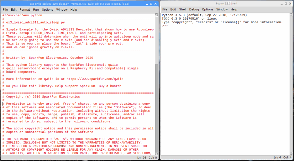
After the sensor detects inactivity for more than 5 seconds, it will automatically enter sleep mode and stop recording data into the FIFO. This conserves power to the accelerometer.
Note: The senor has to be relatively flat on the x-axis in order for it to enter sleep mode. Therefore, users may need to play with a level if their desk isn't level or flat.
Otherwise, users can change the threshold on line 74: myAdxl.setActivityThreshold(10) # 0-255 (62.5mg/LSB) to a higher value, like 40 to increase the inactivity threshold. This means the sensor doesn't have to lie precisely flat, but also means that the sensor requires more acceleration to wake up as well.
Troubleshooting
Below, we have also included some troubleshooting tips for issues that you may come across.
- One of our employees compiled a great list of troubleshooting tips based on the most common customer issues. This is the perfect place to start.
- For any Arduino IDE specific issues, we recommend starting with their troubleshooting guide.
If neither of the troubleshooting guides above were able to help, here are some resources you might have missed. (Most of this material is summarized from the tutorial.):
Raspberry Pi
For comprehensive information or troubleshooting issues, on the Raspberry Pi, users should check out the Raspberry Pi Foundation website and their forum.
As a general guideline, users should use the following resources when looking for technical information or assistance that is specifically related to the Raspberry Pi itself:
- Raspberry Pi FAQ
- Raspberry Pi Beginner's Subforum
- Raspberry Pi Documentation and Help Guides
- Raspberry Pi Forum
- STICKY - Booting Issues
- See other STICKY topics in the Troubleshooting section of the forum
Nvidia Jetson Nano
For comprehensive information or troubleshooting issues, on the Nvidia Jetson, users should check out the Nvidia website and their forum.
As a general guideline, users should use the following resources when looking for technical information or assistance that is specifically related to the Jetson Nano itself:
- Jetson Support Resources
- Jetson Nano Getting Started Guide
- Developer Kit User Manual
- Jetson Nano Wiki
- Nvidia FAQ
- Jetson Forum
- Jetpack Documentation
For users looking for technical assistance, click on the link. There you will find, basic troubleshooting tips and instructions to get started with posting a topic in our forum. Our technical support team will do their best to assist you.
Resources and Going Further
For more information on the SparkFun 3-Axis Digital Accelerometer Breakout - ADXL313 (Qwiic), check out the links below:
- GitHub Hardware Repository -- Home base for the sensor's latest design files
- SparkFun 3-Axis Digital Accelerometer Breakout - ADXL313 (Qwiic) Schematic (PDF)
- SparkFun 3-Axis Digital Accelerometer Breakout - ADXL313 (Qwiic) Eagle Files (ZIP)
- ADXL313 Datasheet (PDF)
- SparkFun ADXL313 Arduino Library -- Source and example files for the Arduino library used in this tutorial.
- Qwiic ADXL313 Python Package
- Product Showcase Video
For more sensor action, check out these other great SparkFun tutorials.