Mini GPS Shield Hookup Guide
Introduction
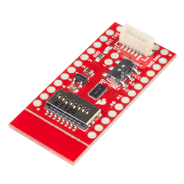
The Mini GPS Shield is a mini version of the SparkFun GPS Logger Shield. While the GPS Logger Shield was designed to work with the Arduino RedBoard, the Mini GPS Shield was designed to work with the Arduino Mini/Micro boards.
SparkFun Mini GPS Shield
GPS-14030Just like its big brother, the Mini GPS Shield equips your Arduino Mini with access to a GPS module and µSD memory card socket for data logging. The board also uses a level shifter, so there's no need to worry about the logic voltage of your Arduino Mini.
Check out the video below to see the Mini GPS Shield in action.
Required Materials
For this guide, you'll need the following:
The wish list above has the 5V Arduino Pro Mini, but the 3.3V Pro Mini, Pro Micro, SAMD21 Mini, or ANY of our Arduino Mini form factor boards will work just as well.
Suggested Reading
If you have never worked with the Arduino Pro Mini or similar platforms before, we suggest having a look at the following tutorials before continuing.
What is an Arduino?
Installing Arduino IDE
How to Install FTDI Drivers
Using the Arduino Pro Mini 3.3V
If you have never worked with GPS before, have a look at our GPS Basics tutorial.
Hardware Overview
Let's go over the Mini GPS Shield in detail.
The Mini GPS Shield will work with any of our Arduino Mini boards. The board uses 3.3V logic, however the logic level converter on the shield allows you to use 5V boards just as easily.
Connecting the GPS
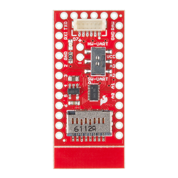
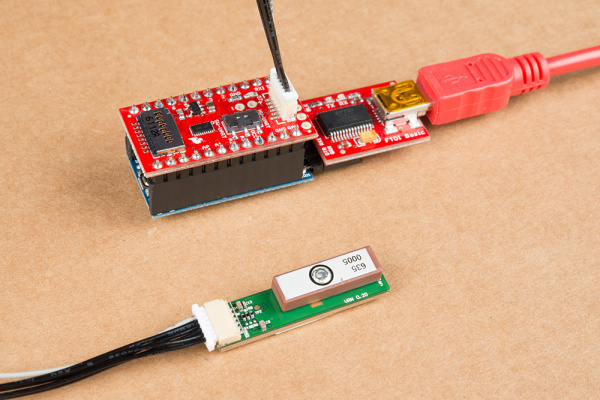
The shield comes with a 6-pin JST connector to connect the GP-735 GPS module. If you already have a GPS module, the JST pins are broken out and labeled to allow you to use just about any GPS module that works down to 3.3V.
NOTE: The RX and TX labels correspond to the data direction on the board. RX should be connected to the GPS TX pin and TX should be connected to the GPS RX pin.
Using the LED
One of the problems of GPS is the time it takes to get your first position reading. Each module is different, but a typical GPS fix takes around 30 seconds. Another downfall is getting a strong enough signal from the the satellites in orbit, which can increase the time it takes to get a position fix. Because of the uncertainty in the time it takes to get a position fix, we included an LED attached to digital pin 7. We'll see in the code below, how to use the LED to illuminate when we have locked in a position.
Software or Hardware Serial?
The GP-735 has a UART that makes communicating with the GPS very easy. Unfortunately, in many cases, the UART is tied up sending debug messages back to our computer. To get around this, we used software serial. Software serial, gives your microcontroller a software defined UART so you can communicate to your GPS while still sending the messages back to your computer. There are other times where you may need to use only the hardware serial, for example if your microcontroller is low on program memory. For this reason, we made switching between hardware and software serial easy, by including a switch that's labeled HW-UART for hardware serial on digital pins 0 and 1, and SW-UART for software serial on digital pins 4 and 5. You can learn more about serial communication here.
GPS Power Saving
The Mini GPS Shield was designed to work with the GP-735 GPS module. If you want to save power, you can pull digital pin 6 LOW, and it will disable power to the GPS. To enable power, you can either pull digital pin 6 HIGH or leave it floating.
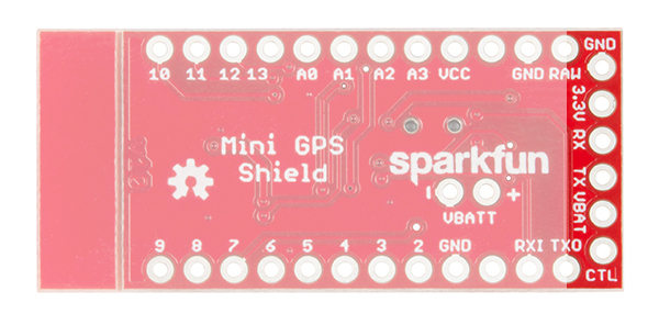
The GP-735 does not have accessible non-volatile memory. This means that when you disconnect power, any settings (baud rate, update rate, etc) will not be saved. If you don't want to reconfigure these settings every time, you'll need to use a backup battery. The backup battery won't be used in the examples below, but, if you need to use it, those pins are labeled VBATT along with a "+" and "-" corresponding to the respective pins. The voltage of VBATT should be between 1.5V and 3.5V.
To Snap or not to Snap
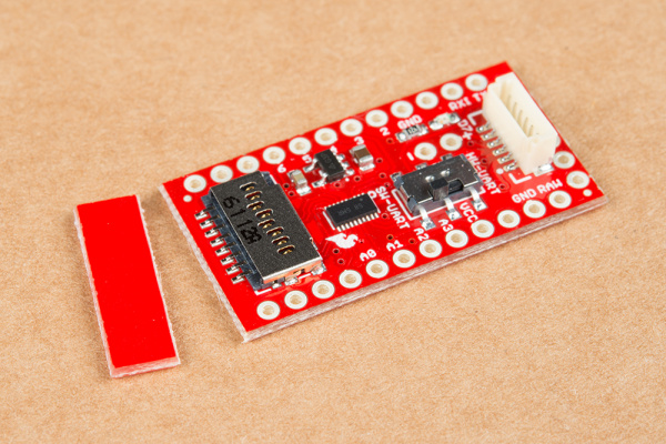
You may have noticed the v-score next to the microSD connector. If you need the board to be as small as possible and aren't planning on using a microSD card, you can easily remove the extra board material by providing a little bit of force to bend the board and snap it off. If you are going to use an SD card, we recommend leaving it on so an accidental bump won't damage or dislodge your microSD card.
Hardware Hookup
Before you can attach your shield, you will need to solder some headers to both the GPS Shiled and the Arduino Pro Mini. We recommend soldering female headers to the Pro Mini and straight male headers for the shield.
Attaching the shield to an Arduino Mini, is very easy but there is one thing to keep in mind: standard Arduino boards, like the SparkFun RedBoard, have pin offsets that make plugging a shield into the board simple, while the mini boards have symmetrical pins, which means it's very easy to plug the shield in the wrong way. Plugging the shield in backwards won't damage either board, but it is something that could be easy to overlook.
The orientation of the shield is pictured below. The correct orientation has the GPS connector on the same side as the USB or FTDI connection and the microSD card over the crystal or reset button.
Arduino Examples
Now that we have everything connected, lets get started with some code. Before we start writing code though, we do need to install a library to parse the GPS messages. If you haven't worked with downloading Arduino libraries before or you just need a quick refresh, check out our tutorial on installing Arduino libraries. The library we need is called TinyGPS++ from Mikal Hart. You can download and install the library from the link below.
Now that we have the library installed, let's look at the code.
In this first example, we'll test our our GPS and make sure we're able to get a signal from the satellites.
language:c
/******************************************************************************
Mini_GPS_Shield_Serial_Example.ino
Example using the Mini GPS Shield with the GP-735
Alex Wende @ SparkFun Electronics
October 12th 2016
~

This sketches uses the Mini GPS Shield with the
GP-735 (https://www.sparkfun.com/products/13670). The Arduino reads the data
from the GPS module on the defined software serial pins, and prints data on
to the serial window.

Resources:
SoftwareSerial.h (included with Arduino IDE)
TinyGPS++.h

Development environment specifics:
Arduino 1.0+
Hardware Version 10

This code is beerware; if you see me (or any other SparkFun employee) at
the local, and you've found our code helpful, please buy us a round!

Distributed as-is; no warranty is given.
******************************************************************************/

#include <TinyGPS++.h>
#include <SoftwareSerial.h>

#define RX_PIN  4 // GPS TX
#define TX_PIN  5 // GPS RX
#define LED_PIN 7 // GPS Fix LED
#define GPS_BAUD  9600  // GP-735 default baud rate

TinyGPSPlus gps;

SoftwareSerial ss(RX_PIN,TX_PIN);

void setup() {
  Serial.begin(115200); // Begin serial communication with computer
  ss.begin(GPS_BAUD); // Begin serial communication with GPS

  pinMode(LED_PIN,OUTPUT);

  Serial.println("Date       Time        Latitude   Longitude   Alt    Course Heading Speed");
  Serial.println("(MM/DD/YY) (HH/MM/SS)     (deg)       (deg)  (ft)                   (mph)");
  Serial.println("-------------------------------------------------------------------------");
}

void loop() {
  char gpsDate[10];
  char gpsTime[10];

  if(gps.location.isValid()){ // GPS has a fix
    digitalWrite(LED_PIN,HIGH); // Turn LED on

    sprintf(gpsDate,"%d/%d/%d", gps.date.month(),gps.date.day(),gps.date.year()); // Build date string
    sprintf(gpsTime,"%d/%d/0%d", gps.time.hour(),gps.time.minute(),gps.time.second());  // Build time string

    Serial.print(gpsDate);
    Serial.print('\t');
    Serial.print(gpsTime);
    Serial.print('\t');
    Serial.print(gps.location.lat(),6);
    Serial.print('\t');
    Serial.print(gps.location.lng(),6);
    Serial.print('\t');
    Serial.print(gps.altitude.feet());
    Serial.print('\t');
    Serial.print(gps.course.deg(),2);
    Serial.print('\t');
    Serial.println(gps.speed.mph(),2);
  }
  else  // GPS is looking for satellites, waiting on fix
  {
    digitalWrite(LED_PIN,LOW);  // Turn LED off
    Serial.print("Satellites in view: ");
    Serial.println(gps.satellites.value());
  }
  smartDelay(1000);
}

// Delay ms while still reading data packets from GPS
static void smartDelay(unsigned long ms)
{
  unsigned long start = millis();
  do
  {
    while(ss.available())
    {
      gps.encode(ss.read());
    }
  } while(millis() - start < ms);
}
Our second example is very similar to our first example. In this example though, instead of displaying the GPS data in just the serial window, we'll also log the data to a microSD card. Note that this example makes use of the built-in SD library in the Arduino IDE.
language:c
/******************************************************************************
Mini_GPS_Shield_Data_Log_Example.ino
Example using the Mini GPS Shield with the GP-735
Alex Wende @ SparkFun Electronics
October 12th 2016
~

This sketches uses the Mini GPS Shield with the
GP-735 (https://www.sparkfun.com/products/13670) and a microSD card. The
Arduino reads the data from the GPS module on the defined software serial
pins, and saves the data to a SD card.

Resources:
SoftwareSerial.h (included with Arduino IDE)
SD.h (included with Arduino IDE)
SPI.h (included with Arduino IDE)
TinyGPS++.h

Development environment specifics:
Arduino 1.0+
Hardware Version 10

This code is beerware; if you see me (or any other SparkFun employee) at
the local, and you've found our code helpful, please buy us a round!

Distributed as-is; no warranty is given.
******************************************************************************/

#include <SPI.h>
#include <SD.h>
#include <TinyGPS++.h>
#include <SoftwareSerial.h>

#define RX_PIN  4 // GPS TX
#define TX_PIN  5 // GPS RX
#define LED_PIN 7 // GPS Fix LED
#define CHIP_SELECT 10  // uSD card
#define GPS_BAUD  9600  // GP-735 default baud rate

TinyGPSPlus gps;
File myFile;
SoftwareSerial ss(RX_PIN,TX_PIN);

void setup() {
  Serial.begin(115200); // Begin serial communication with computer
  ss.begin(GPS_BAUD); // Begin serial communication with GPS

  pinMode(LED_PIN,OUTPUT);

  Serial.print("Initializing SD card...");

  // see if the card is present and can be initialized:
  if (!SD.begin(CHIP_SELECT)) {
    Serial.println("Card failed, or not present");
    // don't do anything more:
    return;
  }
  Serial.println("card initialized.");

  myFile = SD.open("data.txt", FILE_WRITE); // Create or open a file called "data.txt" on the SD card
  if(myFile)
  {
    if(myFile.size() == 0)  // Only create the header if there isn't any data in the file yet
    {
      myFile.println("Date\t\tTime\t\tLatitude\tLongitude\tAlt\tCourse\tSpeed");
      myFile.println("MM/DD/YYYY\tHH/MM/SS\tdeg\t\tdeg\t\tft\t\tmph");
      myFile.println("-------------------------------------------------------------------------------------");
    }
    myFile.close(); // Close the file to properly save the data
  }
  else {
    // if the file didn't open, print an error:
    Serial.println("error opening test.txt");
  }
}

void loop() {
  char gpsDate[10], gpsTime[10];

  if(gps.location.isValid()){ // GPS has a fix
    digitalWrite(LED_PIN,HIGH); // Turn LED on
    myFile = SD.open("data.txt", FILE_WRITE); // Open file "data.txt"
    if(myFile)
    {
      // Get date and time
      sprintf(gpsDate,"%d/%d/%d", gps.date.month(),gps.date.day(),gps.date.year());
      if(gps.time.second() < 10){
        sprintf(gpsTime,"%d/%d/0%d", gps.time.hour(),gps.time.minute(),gps.time.second());
      }
      else
      {
        sprintf(gpsTime,"%d/%d/%d", gps.time.hour(),gps.time.minute(),gps.time.second());
      }

      // Save data to SD card
      myFile.print(gpsDate);
      myFile.print('\t');
      myFile.print(gpsTime);
      myFile.print('\t');
      myFile.print(gps.location.lat(),6);
      myFile.print('\t');
      myFile.print(gps.location.lng(),6);
      myFile.print('\t');
      myFile.print(gps.altitude.feet());
      myFile.print('\t');
      myFile.print(gps.course.deg(),2);
      myFile.print('\t');
      myFile.println(gps.speed.mph(),2);

      // Print GPS data to serial window
      Serial.print(gpsDate);
      Serial.print('\t');
      Serial.print(gpsTime);
      Serial.print('\t');
      Serial.print(gps.location.lat(),6);
      Serial.print('\t');
      Serial.print(gps.location.lng(),6);
      Serial.print('\t');
      Serial.print(gps.altitude.feet());
      Serial.print('\t');
      Serial.print(gps.course.deg(),2);
      Serial.print('\t');
      Serial.println(gps.speed.mph(),2);
    }

    myFile.close(); // Close the file to properly save the data
  }
  else  // GPS is looking for satellites, waiting on fix
  {
    digitalWrite(LED_PIN,LOW);  // Turn LED off
    Serial.print("Satellites in view: ");
    Serial.println(gps.satellites.value());
  }

  smartDelay(1000);
}

// Delay ms while still reading data packets from GPS
static void smartDelay(unsigned long ms)
{
  unsigned long start = millis();
  do
  {
    while(ss.available())
    {
      gps.encode(ss.read());
    }
  } while(millis() - start < ms);
}
Troubleshooting Tips
If you're testing your GPS inside, make sure you're next to a window. One of the problems with GPS is the radio waves have a difficult time passing through roofs and ceilings, so, the closer the GPS is to being outside, the better. If you still aren't reading from enough satellites to get a position fix, try pointing the GPS antenna in a different direction.
Due to the symmetrical pins of the mini boards, installing the shield backwards is an easy mistake to make. The correct orientation has the GPS connector on the same side as the USB or FTDI connection and the microSD card over the crystal and reset button. See the Hardware Hookup section for a picture of the correct orientation.
If you are unable to access the SD card, make sure your card is installed with the pins facing down and that you've initialized the SD card's chip select as pin 10 when you call SD.begin(CHIP_SELECT).
Resources and Going Further
For more information about the Mini GPS Shield, check out the links below:
Going Further
Now that you've got the Mini GPS Shield up and running, what project are you going to use this shield for? Need a little inspiration? Check out some of these tutorials!
- GPS Wall Clock -- This project uses a GPS module to create a wall clock that you never need to set!
- GPS Differential Vector Pointer -- In this tutorial you’ll learn how to use GPS receivers to have two objects, a base and a target, point towards one another. This can be used to aim sensors, antennas, lasers, etc. from one object to another over long distances.
