smôl ZOE-M8Q Hookup Guide
Introduction
smôl is a new board format and, as the name suggests, they're really small!
smôl ZOE-M8Q
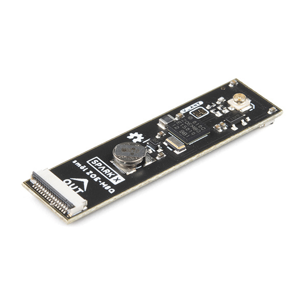
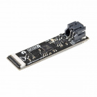
SPX-18623The smôl ZOE-M8Q is a GNSS (Global Navigation Satellite System) receiver board based on the excellent u-blox ZOE-M8Q.
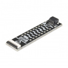
Each smôl board measures just 1.60" by 0.42" (40.6mm by 10.7mm). We made the boards just wide enough so we could squeeze USB-C and 16-way Flexible Printed Circuit (FPC) connectors on there. Some of the boards have components on both top and bottom layers which again helps keep the boards small.
smôl boards are designed to stack one on top of the other, using 16-way 0.5mm-pitch FPCs to provide the interconnect from one board to the next. Each board has an IN FPC connector on the bottom layer and an OUT FPC connector on the top layer. The boards stack in a zig-zag daisy chain; signals and power are passed from one board to the next up and down the chain through the FPCs.
Required Materials
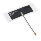
As a minimum, you're going to need a u.FL GNSS antenna:
The ZOE-M8Q Peripheral Board is part of the smôl ecosystem. Why not pair it with one of the smôl Processor Boards?
smôl ESP32
SPX-18619
To be able to reduce the sleep current below 10µA, you're going to want to pair the ESP32 with one of our intelligent smôl Power Boards:
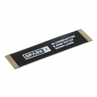
Don't forget that you will need Flexible Printed Circuits to connect your smôl boards together. You're going to need one FPC per board. Our 36mm FPC is the perfect length if you want the smôl boards to stack neatly, one on top of the other.
Need to do some prototyping with smôl? Or want to connect the smôl ZOE-M8Q to another Qwiic board? The smôl Header is perfect for that:
Suggested Reading
This is the hookup guide for the smôl ZOE-M8Q Peripheral Board. Click the button below if you want to find out more about smôl itself.
We recommend taking a look through the following tutorials if you are not familiar with the concepts covered in them:
I2C
Three Quick Tips About Using U.FL
Hardware Overview
In this section we'll cover what's included on the smôl ZOE-M8Q Peripheral Board.
GNSS Capabilities
The u-blox ZOE-M8Q is able to connect to up to three different GNSS constellations at a time making it very accurate for its size.
Below are the listed capabilities of the GNSS unit:
| GNSS | GPS and GLONASS | GPS | GLONASS | BeiDou | Galileo | ||
|---|---|---|---|---|---|---|---|
| Horizontal Position Accuracy | 2.5m | 2.5m | 4m | 3m | 3m | ||
| Max Navigation Update Rate | ROM | 10Hz | 18Hz | 18Hz | 18Hz | 18Hz | |
| Flash | 5Hz | 10Hz | 10Hz | 10Hz | 10Hz | ||
| Time-To-First-Fix | Cold Start | 26s | 29s | 30s | 34s | 45s | |
| Hot Start | 1s | 1s | 1s | 1s | 1s | ||
| Sensitivity | Tracking and Navigation | -167dBm | -166dBm | -166dBm | -160dBm | -159dBm | |
| Reacquisition | -160dBm | -160dBm | -156dBm | -157dBm | -153dBm | ||
| Cold Start | -148dBm | -148dBm | -145dBm | -143dBm | -138dBm | ||
| Hot Start | -157dBm | -157dBm | -156dBm | -155dBm | -151dBm | ||
| Velocity Accuracy | 0.05m/s | ||||||
| Heading Accuracy | 0.3 degrees |
Power
Power for this board - and all smôl boards - should be 3.3V.
Battery
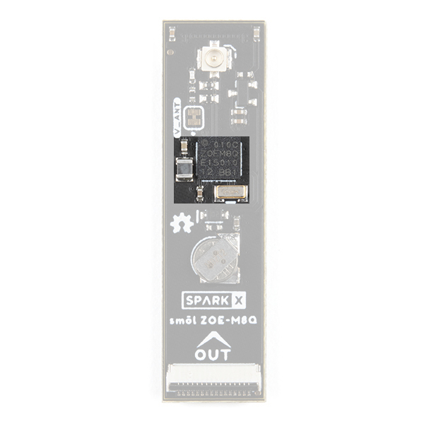
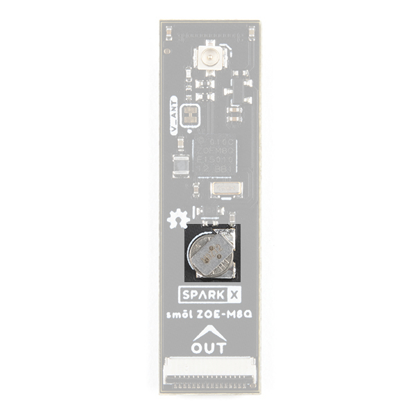
The small metal disk in the center of the board is a small lithium battery. This battery does not provide power to the IC like the 3.3V system does, but to relevant systems inside the IC that allow for a quick reconnection to satellites. The time to first fix will be about ~29 seconds, but after the product has a lock, that battery will allow for a one second time to first fix. This is known as a hot start and lasts for four hours after the board is powered down. The battery provides over a year's worth of power to the backup system and charges slowly when smôl 3.3V is powered.
Jumpers
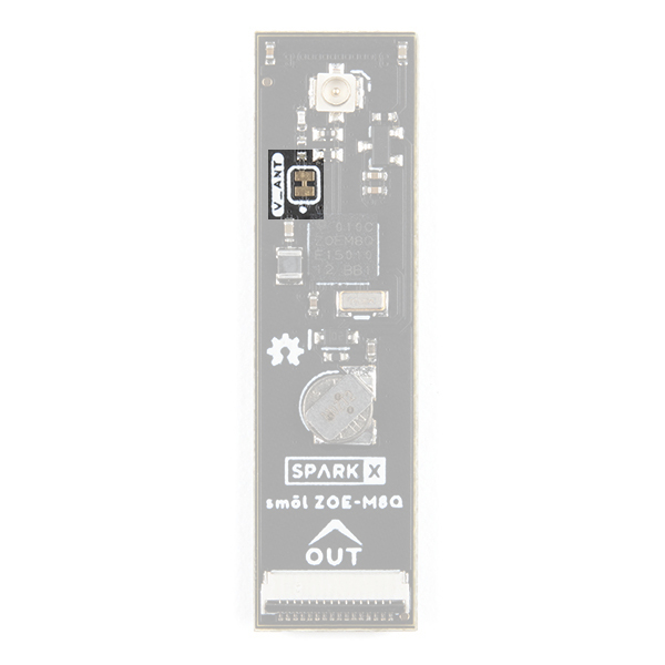
There is only one jumper on the top of this product, labelled V_ANT. By default, 3.3V power is provided on the u.FL connector for an active antenna. Cutting the V_ANT jumper disconnects the 3.3V power.
u.FL Connector
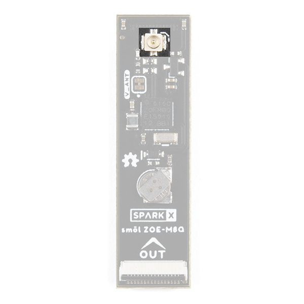
The u.FL connector on the board is where you will plug in your antenna. This is a compact connector for RF antennas, that has the same function as the traditional SMA connector. You may be more familiar and even own some antennas that use SMA connectors; never fear, we carry a U.FL to SMA cable adapter. Check out our tutorial on using U.FL connectors, if this is your first.
Power Switching
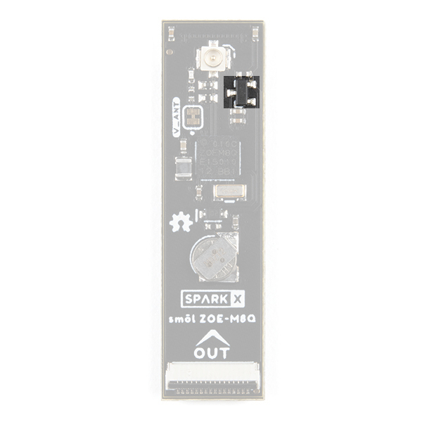
The smôl ZOE-M8Q includes an on-board power switch (MOSFET):
Power for the ZOE-M8Q is controlled via the smôl GPIO0 signal. Leave GPIO0 floating or pull high to disable power to the ZOE-M8Q (default state). Pull the smôl GPIO0 signal low to enable power for the ZOE-M8Q.
FPC Connections
Like all of our smôl boards, the ZOE-M8Q Peripheral Board is equipped with two 16-way 0.5mm-pitch Flexible Printed Circuit connectors. FPCs are used to link the smôl boards together in a daisy-chain.
The pin-out for the smôl ZOE-M8Q IN connector is as follows:
| IN Connector Pin No. | Signal Name | Function | Notes |
|---|---|---|---|
| 1 | PROC_PWR_EN | Processor Power Enable | Not used |
| 2 | 3V3 | 3.3V Power Rail | |
| 3 | GND | Power Ground / 0V | |
| 4 | SCLK | SPI Clock | Not used |
| 5 | COPI | SPI Controller Out Peripheral In | Not used |
| 6 | CIPO | SPI Controller In Peripheral Out | Not used |
| 7 | CS0 | SPI Chip Select 0 | Not used |
| 8 | CS1 | SPI Chip Select 1 | Not used |
| 9 | CS2 | SPI Chip Select 2 | Not used |
| 10 | GPIO0 | ZOE-M8Q Power Control | Pull low to enable power for the ZOE-M8Q |
| 11 | GPIO1 | General Purpose Input / Output 1 | Connected to Pin 10 (GPIO0) on the OUT connector |
| 12 | SDA | I2C Data | Used for ZOE-M8Q communication |
| 13 | SCL | I2C Clock | Used for ZOE-M8Q communication |
| 14 | GND | Power Ground / 0V | |
| 15 | 3V3 | 3.3V Power Rail | |
| 16 | V_USB | USB Power Rail (5V) | Not used |
The pin-out for the smôl ZOE-M8Q OUT connector is as follows:
| OUT Connector Pin No. | Signal Name | Function | Notes |
|---|---|---|---|
| 1 | PROC_PWR_EN | Processor Power Enable | Not used |
| 2 | 3V3 | 3.3V Power Rail | |
| 3 | GND | Power Ground / 0V | |
| 4 | SCLK | SPI Clock | Not used |
| 5 | COPI | SPI Controller Out Peripheral In | Not used |
| 6 | CIPO | SPI Controller In Peripheral Out | Not used |
| 7 | CS0 | SPI Chip Select 0 | Not used |
| 8 | CS1 | SPI Chip Select 1 | Not used |
| 9 | CS2 | SPI Chip Select 2 | Not used |
| 10 | GPIO0 | General Purpose Input / Output 0 | Connected to Pin 11 (GPIO1) on the IN connector |
| 11 | GPIO1 | Not connected | |
| 12 | SDA | I2C Data | Used for ZOE-M8Q communication |
| 13 | SCL | I2C Clock | Used for ZOE-M8Q communication |
| 14 | GND | Power Ground / 0V | |
| 15 | 3V3 | 3.3V Power Rail | |
| 16 | V_USB | USB Power Rail (5V) | Not used |
We use a technique called waterfalling on the GPIO signals. If you haven't used waterfalling before, please check out the smôl Hookup Guide.
smôl Specifics
Interface:
- I2C
- Default Address: 0x42 (unshifted)
GPIO:
- GPIO0 controls the power for the ZOE-M8Q
- Pull GPIO0 high or leave floating to disable power for the ZOE-M8Q (default state)
- Pull GPIO0 low to enable power for the ZOE-M8Q
Please remember that the smôl GPIO pins use waterfalling. The Arduino digital pin number for GPIO0 will depend on which Processor Board you are using and where the ZOE-M8Q is placed in the smôl stack. Please consult the smôl Hookup Guide for more details.
Arduino Example: Get Position
If you are using the smôl ESP32 Processor Board, you are going to want to install the CP210x USB Driver and Arduino Boards Package for the ESP32 first. Please see the smôl ESP32 Hookup Guide for more details.
The smôl ZOE-M8Q GNSS peripheral board is fully compatible with the SparkFun u-blox GNSS Arduino Library. You can install the library through the Arduino IDE Library Manager by searching for SparkFun u-blox GNSS. Alternatively, you can grab the library from GitHub or can download it as a zip file by clicking the button below:
The following example is based on Example3_GetPosition from the u-blox GNSS library. The only difference is the two extra lines of code which pull GPIO0 low to enable power for the ZOE-M8Q. Upload the code onto your processor board and open the Serial Monitor or a terminal emulator at 115200 baud to see the output.
language:c
#include <Wire.h> //Needed for I2C to GNSS

#include <SparkFun_u-blox_GNSS_Arduino_Library.h> //http://librarymanager/All#SparkFun_u-blox_GNSS
SFE_UBLOX_GNSS myGNSS;

void setup()
{
  delay(1000);

  Serial.begin(115200);
  Serial.println("SparkFun u-blox example for the smôl ZOE-M8Q");

  // GNSS power is disabled by default on the smôl ZOE-M8.
  // We need to pull GPIO0 low to enable the power.
  // On the smôl ESP32, GPIO0 is connected to digital pin 27.
  // smôl uses waterfalling:
  //  If you have an intermediate smôl board between the ESP32 and the ZOE-M8Q
  //  and that board also uses GPIO0, then the ZOE-M8Q's power enable will be connected
  //  to GPIO1 instead which is digital pin 26 on the smôl ESP32.
  pinMode(27, OUTPUT);
  digitalWrite(27, LOW); // Pull GPIO0 (digital pin 27) low to enable power for the ZOE-M8Q

  delay(1000); // Give the ZOE-M8Q some time to power up

  Wire.begin();

  //myGNSS.enableDebugging(); //Uncomment this line to enable helpful debug messages on Serial

  if (myGNSS.begin() == false) //Connect to the u-blox module using Wire port
  {
    Serial.println(F("u-blox GNSS not detected at default I2C address. Please check wiring. Freezing."));
    while (1);
  }

  myGNSS.setI2COutput(COM_TYPE_UBX); //Set the I2C port to output UBX only (turn off NMEA noise)
  myGNSS.saveConfigSelective(VAL_CFG_SUBSEC_IOPORT); //Save (only) the communications port settings to flash and BBR
}

void loop()
{
  //The module only responds when a new position is available

  Serial.print(myGNSS.getYear());
  Serial.print("/");
  Serial.print(myGNSS.getMonth());
  Serial.print("/");
  Serial.print(myGNSS.getDay());
  Serial.print(" ");
  Serial.print(myGNSS.getHour());
  Serial.print(":");
  Serial.print(myGNSS.getMinute());
  Serial.print(":");
  Serial.print(myGNSS.getSecond());

  Serial.print(F(" Lat: "));
  Serial.print(myGNSS.getLatitude());

  Serial.print(F(" Long: "));
  Serial.print(myGNSS.getLongitude());
  Serial.print(F(" (degrees * 10^-7)"));

  Serial.print(F(" Alt: "));
  Serial.print(myGNSS.getAltitudeMSL());
  Serial.print(F(" (mm)"));

  Serial.print(F(" SIV: "));
  Serial.print(myGNSS.getSIV());

  Serial.println();
}
Troubleshooting
If the smôl ZOE-M8Q does not appear to be working, have you remembered to pull its GPIO0 signal low to enable the power? By default, power for the ZOE-M8Q is disabled. Pulling GPIO0 low enables the power.
If you are connecting to the smôl ZOE-M8Q via the smôl Header - without a Processor Board - you will need to tie the correct GPIO signal to GND with a jumper wire.
The Molex Flexible GNSS Antenna - u.FL is designed to work without a ground plane. It works best when positioned at least 40mm away from a ground plane. You will get little or no signal if: you stick the antenna to a metal enclosure, or position the antenna close to your battery or circuit boards. Position the antenna in clear space for best results. Please refer to the antenna Application Specification for more details.
Resources and Going Further
For more information about the smôl ZOE-M8Q Peripheral Board, check out the following links:
smôl ZOE-M8Q Documentation:
- Schematic
- Eagle Files
- Datasheet (ZOE-M8Q)
- Integration Manual (ZOE-M8Q)
- Product Summary (ZOE-M8Q)
- GitHub Hardware Repo
- Arduino Examples
- SparkFun u-blox GNSS Arduino Library
smôl Documentation:
