smôl Hookup Guide
Introduction
Our RedBoards are great. But don't they sometimes seem a little BIG?!
Enter smôl, a new range of boards which are both small in size and small on current draw. It's a smôl world!
When we designed our ARGOS Satellite Transceiver Shield - ARTIC R2, we knew that people would want to use it for applications like wildlife tracking, ocean buoys, environmental monitoring or transferring emergency medical information. But what if you want to develop something much smaller? Say, a small dart for whale tracking, or a small backpack for avian tracking. Or you just need your battery to last for months. smôl is designed to meet those needs.
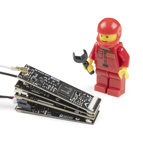
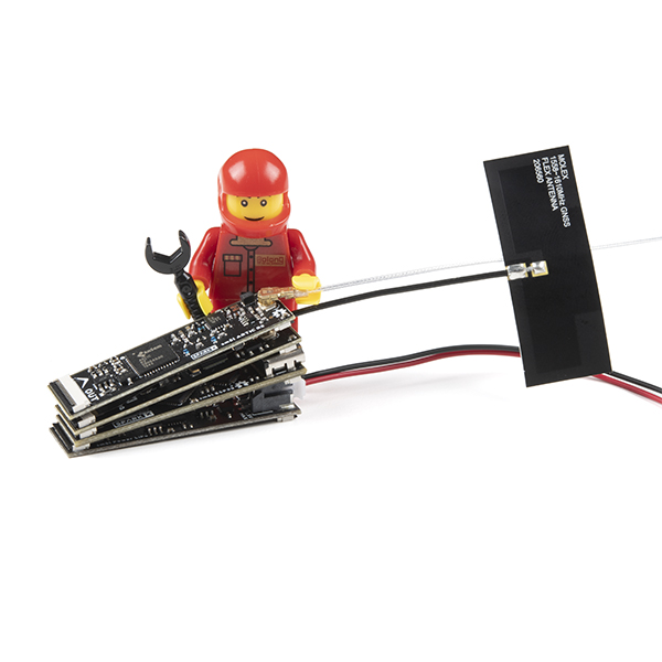
The stack in the above photo is a complete ARTIC R2 satellite tracker capable of transmitting 2.5m accuracy position fixes five times per day to the ARGOS satellite network (ARGOS provides global coverage, including the oceans and the polar regions) using a 400mAh battery for over 100 days!
The smôl family of boards includes:
Processor Boards
smôl ESP32
SPX-18619GNSS (GPS) Boards
smôl ZOE-M8Q
SPX-18623Satellite Communication Boards
smôl ARTIC R2
SPX-18618Power Boards
Essentials
Accessories
- Whether it's for assembling a kit, hacking an enclosure, or creating your own parts; the DIY skill is all about knowing how to use tools and the techniques associated with them.
- If it requires power, you need to know how much, what all the pins do, and how to hook it up. You may need to reference datasheets, schematics, and know the ins and outs of electronics.
What is smôl?
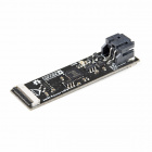
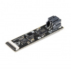
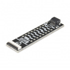
smôl is a new board format and, as the name suggests, they're really small!
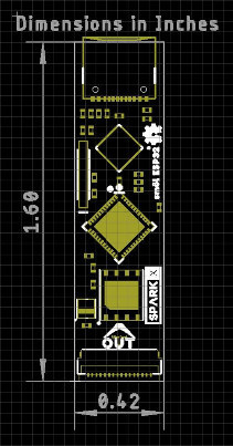
Each smôl board measures just 1.60" by 0.42" (40.6mm by 10.7mm). We made the boards just wide enough so we could squeeze USB-C and 16-way Flexible Printed Circuit (FPC) connectors on there. Some of the boards have components on both top and bottom layers which again helps keep the boards small.
smôl boards are designed to stack one on top of the other, using 16-way 0.5mm-pitch FPCs to provide the interconnect from one board to the next. Each board has an IN FPC connector on the bottom layer and an OUT FPC connector on the top layer. The boards stack in a zig-zag daisy chain; signals and power are passed from one board to the next up and down the chain through the FPCs.
We've designed a smôl Header too, which you can use to mount your smôl stack on a standard breadboard or another PCB. The Header only has an OUT connector so it needs to go at the bottom of your stack.
The order in which you connect the boards is important and we'll cover that in the next sections.
FPC Connections
We love Flexible Printed Circuit (FPC) connections and we're using them in more and more of our products.
Each smôl board (except the Header) comes with two 16-way FPC connectors, labelled IN and OUT. The IN connector is on the bottom of each board, the OUT is on top. Matching FPCs connect the OUT connector on one board to the IN connector on the next.
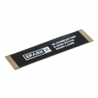
Our 36mm FPC is the perfect length if you want the smôl boards to stack neatly, one on top of the other. The connectors have "dual contacts" (contacts top and bottom) and so it does not matter which way round you insert the FPC, it will always make contact.
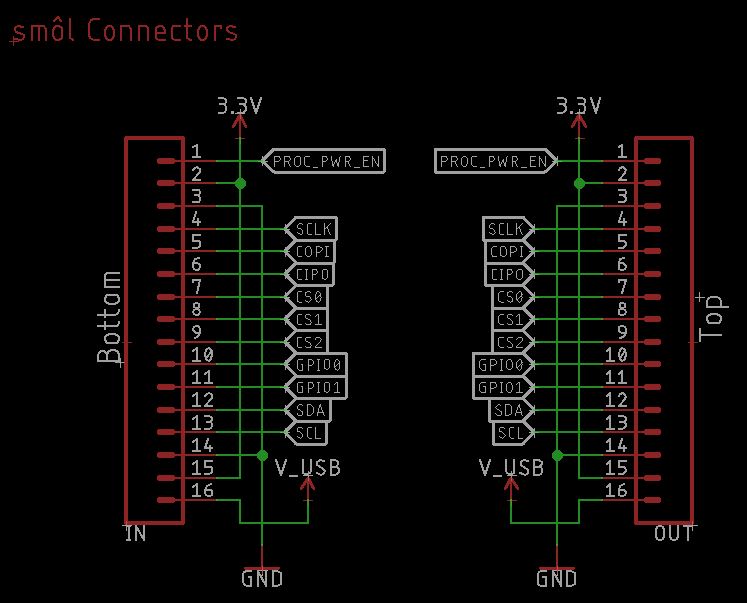
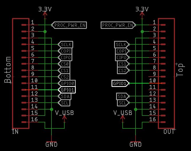
We wanted the smôl boards to be as small as possible and so we've put a lot of thought into the signals on those 16 FPC connections to make them as efficient as possible. The standard pin-out of the connector is as follows:
| Connector Pin No. | Signal Name | Function |
|---|---|---|
| 1 | PROC_PWR_EN | Processor Power Enable |
| 2 | 3V3 | 3.3V Power Rail |
| 3 | GND | Power Ground / 0V |
| 4 | SCLK | SPI Clock |
| 5 | COPI | SPI Controller Out Peripheral In |
| 6 | CIPO | SPI Controller In Peripheral Out |
| 7 | CS0 | SPI Chip Select 0 |
| 8 | CS1 | SPI Chip Select 1 |
| 8 | CS2 | SPI Chip Select 2 |
| 10 | GPIO0 | General Purpose Input / Output 0 |
| 11 | GPIO1 | General Purpose Input / Output 1 |
| 12 | SDA | I2C Data |
| 13 | SCL | I2C Clock |
| 14 | GND | Power Ground / 0V |
| 15 | 3V3 | 3.3V Power Rail |
| 16 | V_USB | USB Power Rail (5V) |
On our Eagle schematics, the connections usually look like this:
We say "usually" because the exact connections depend on the board type. More about that in a moment.
First, let's talk about what each pin does:
Pin 1: PROC_PWR_EN
Processor Power Enable is a signal which is passed up and down the smôl stack. It is connected to the enable pin of the 3.3V voltage regulator on the processor board. If PROC_PWR_EN is pulled high, or is left floating, the processor board voltage regulator will be enabled and will generate 3.3V from USB-C.
When you connect a Power Board to your smôl stack, PROC_PWR_EN allows the power board to disable the regulator on the processor board. The power board is then responsible for generating the 3.3V power rail for the entire smôl stack. We do this for two reasons: to prevent the power board and processor board regulators from fighting each other; and to allow the power board to power down the entire smôl stack even if USB is connected.
One of the clever features of smôl is that the power boards can be instructed to power down the whole stack for a pre-defined duration. Power down durations of a few 10's of milliseconds to several days are possible. During power down the only device left running is the ATtiny processor on the power board, which typically consumes less than 10 microamps. PROC_PWR_EN allows smôl to avoid the quiescent current normally drawn by the processor regulator.
Pins 2 and 15: 3.3V Power
Pins 2 and 15 carry 3.3V power up and down the smôl stack. 3.3V can be generated by a processor board, powered by USB-C. Or, 3.3V power can be generated by one of our power boards.
As described above, the power board can disable the regulator on the processor board via the PROC_PWR_EN pin, avoiding the associated quiescent current draw.
Pins 3 and 14: GND
Pins 3 and 14 are the smôl Power Ground or 0V pins.
You will note that the highest speed smôl signals (SPI SCLK and I2C SCL) are run adjacent to the GND connections to minimize EMI.
Pins 4-6: SPI SCLK, COPI and CIPO
Pins 4-6 carry the clock and data signals for the Serial Peripheral Interface (SPI).
The Processor Board is the SPI Controller and can communicate with smôl Peripheral boards at high data rates.
SPI devices share common clock and data signals but require an individual Chip Select signal. The smôl Chip Select signals are described in the next paragraph.
Pins 7-9: SPI CS0, CS1 and CS2
Pins 7-9 are the smôl SPI Chip Select signals and allow up to three SPI Peripheral Boards to be connected into your smôl stack.
We use a technique called waterfalling when linking the chip select lines from one smôl board to the next. There is a full description of this in the SPI Chip Select Waterfalling section of this guide.
If your favorite 3.3V SPI breakout board is not yet available in smôl format, you can connect it via the breakout pins on the smôl Header.
Pins 10 and 11: GPIO0 and GPIO1
Pins 10 and 11 carry two General Purpose Input / Output signals: GPIO0 and GPIO1. These are typically used as power control signals to power down individual Peripheral Boards, again to allow the current draw to be minimized as much as possible.
Just like the SPI Chip Select signals, GPIO0 and GPIO1 are also waterfalled. If a Peripheral Board uses GPIO0, then GPIO1 is waterfalled onto GPIO0 of the board's OUT connector. Please see the full description of this in the GPIO Waterfalling section of this guide.
Pins 12 and 13: I2C SDA and SCL
Pins 12 and 13 carry the data and clock signals for Inter-Integrated Circuit (I2C) communication.
Multiple I2C boards can be connected to smôl provided each has a unique address.
If your favorite Qwiic board is not yet available in smôl format, you can connect it via the Qwiic connector on the smôl Header.
Pin 16: V_USB
Pin 16 carries 5V power from the USB-C connector on the Processor Board up and down the smôl stack.
V_USB is used by the smôl Power Board LiPo to recharge the LiPo battery when USB-C is connected. We limited the charge current to 100mA to avoid drawing too much current through the single V_USB FPC trace.
Pin Numbering
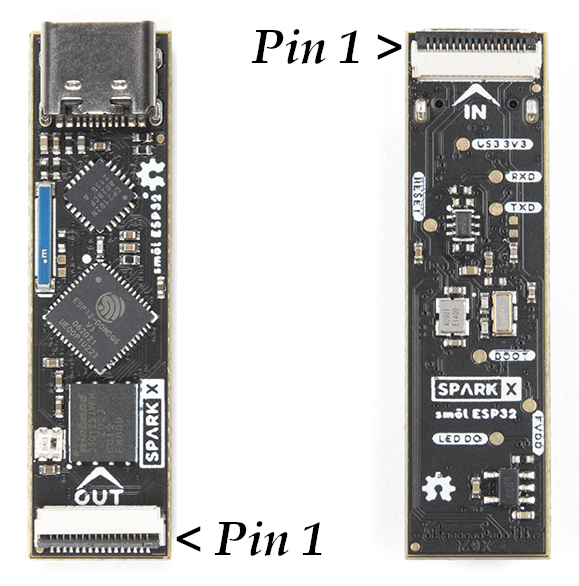
Just to clarify which is pin 1:
When viewed from the front or top of the board, pin 1 of the OUT connector is on the right.
When the board is turned over, pin 1 of the IN connector is on the left.
SPI Chip Select Waterfalling
smôl allows you to connect up to three Serial Peripheral Interface (SPI) peripheral boards into your stack.
SPI devices share common clock and data signals but require an individual Chip Select signal. Here's how we connect the Chip Select signal on smôl using a technique called waterfalling.
The three chip select signals are called CS0, CS1 and CS2. On the ESP32 Processor Board, these are connected to GPIO5, GPIO14 and GPIO13 respectively. In Arduino terms, they are D5, D14 and D15, or Digital Pins 5, 14 and 13.
Waterfalling is a technique where:
- if a Peripheral Board needs an SPI Chip Select, it will always use CS0 from the IN connector
- the unused Chip Select lines CS1 and CS2 are then passed to the OUT connector as CS0 and CS1
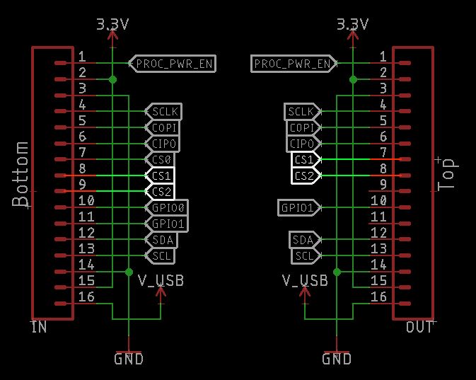
Let's see that in action. Here are the FPC connections on the smôl ARTIC R2:
The smôl ARTIC R2 uses SPI communication and so uses CS0 (Pin 7) from the IN connector.
CS1 (IN Pin 8) and CS2 (IN Pin 9) are not used and so are connected directly to the OUT connector but as Pins 7 and 8 (not Pins 8 and 9).
If the ARTIC R2 is placed immediately above the ESP32 Processor Board in the smôl stack, its Chip Select is connected to ESP32 Digital Pin 5.
If another SPI Peripheral Board were placed above the ARTIC R2 board, it too would use CS0 but its CS0 would be connected to ESP32 Digital Pin 14 (not 5) thanks to the waterfalling.
The important 'rule' is: Peripheral Boards must be placed above the Processor Board in the smôl stack
If you accidentally place a Peripheral Board below the processor board, no damage will be done. But the Peripheral Board will not function because its Chip Select signal will be left floating.
Power Boards are a special case. They only use I2C for communication and so can be placed anywhere in the stack. The natural place for them is below the Processor Board, but you can place them above if you want to.
The smôl Header only has an OUT connector so it needs to go at the very bottom of your stack.
GPIO Waterfalling
smôl provides two General Purpose Input / Output signals. These are generally used for power control, allowing individual smôl boards to be completely powered down to minimise the current draw
Just like the SPI Chip Select signals, the two GPIO signals also use waterfalling.
The two GPIO signals are called GPIO0 and GPIO1. On the ESP32 Processor Board, these are connected to GPIO27 and GPIO26 respectively. In Arduino terms, they are D27 and D26, or Digital Pins 27 and 26.
Here are the FPC connections on the smôl ARTIC R2 again:
The smôl ARTIC R2 uses GPIO0 for power control and so uses GPIO0 (Pin 10) from the IN connector.
GPIO1 (IN Pin 11) is not used and so is connected directly to the OUT connector but as Pin 10 (not Pin 11).
If the ARTIC R2 is placed immediately above the ESP32 Processor Board in the smôl stack, its Power Enable is connected to ESP32 Digital Pin 27.
If another Peripheral Board were placed above the ARTIC R2 board, it too could use GPIO0 but it would be connected to ESP32 Digital Pin 26 (not 27) thanks to the waterfalling.
The important 'rule' is: Peripheral Boards must be placed above the Processor Board in the smôl stack
If you accidentally place a Peripheral Board below the processor board, no damage will be done. But the Peripheral Board will not function as expected because its GPIO signal will be left floating.
Power Boards are a special case. They only use I2C for communication and so can be placed anywhere in the stack. The natural place for them is below the Processor Board, but you can place them above if you want to.
The smôl Header only has an OUT connector so it needs to go at the very bottom of your stack.
Assembly
smôl boards are designed to stack one on top of the other, using 16-way 0.5mm-pitch FPCs to provide the interconnect from one board to the next. Each board has an IN FPC connector on the bottom layer and an OUT FPC connector on the top layer. The boards stack in a zig-zag daisy chain; signals and power are passed from one board to the next up and down the chain through the FPCs.
We use "back-flip" "dual contact" connectors to make inserting the FPCs as frustration-free as possible. The "back-flip" makes the connector very compact and it is easy to flip the lever with your fingernail. We find them much easier to use than traditional slide connectors. "dual contact" connectors have contacts both top and bottom so it does not matter which way round you insert the FPC. Either way up is OK.
There are some simple steps you need to follow when connecting your boards:
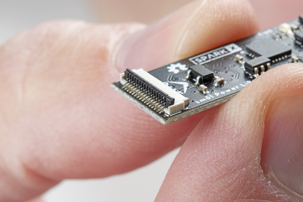
Lift the Back-Flip Lever
Lift the back-flip lever with your fingernail or a small screwdriver:
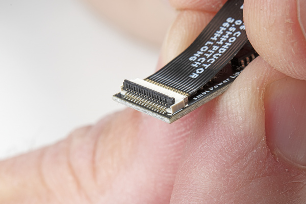
Insert the FPC
Insert the FPC. Give it a little jiggle and apply a little pressure until it is fully inserted. You can insert the FPC either way up:
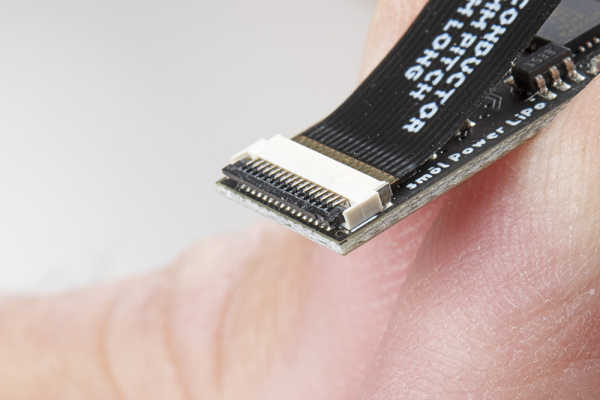
Close the Back-Flip Lever
Use your fingernail or a small screwdriver to close the back-flip lever, securing the FPC:
Expert Tip:
Let's say you are connecting a ZOE-M8Q GNSS Peripheral Board to an ESP32 Processor Board. As described in the previous section, you are going to position the ZOE-M8Q above the ESP32. Our expert tip is to:
- Turn the ZOE-M8Q board over and lift the back-flip lever on the IN connector
- Orientate the FPC so the writing and gold fingers will be against the underside of the ZOE-M8Q board. This reveals the brown stiffener on the back of the FPC.
- Start to insert the FPC into the IN connector and then put your fingernail against the edge of the stiffener. There is a small step on the edge of the stiffener.
- Use your fingernail to gently drag the FPC stiffener into position, making sure the FPC ends up fully inserted into the connector.
- Close the back-flip lever on the IN connector.
- Lift the back-flip lever on the ESP32 OUT connector.
- Start to insert the other end of the FPC into the OUT connector.
- Hold the ZOE-M8Q board and give it a little jiggle to help insert the FPC. It is easier to hold the ZOE-M8Q board than it is to hold the FPC itself.
- Make sure the FPC is fully inserted, then close the OUT connector back-flip lever.
Simples!
Completed Stack
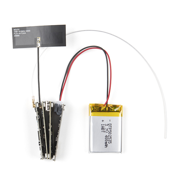
Here's how your completed smôl stack should look once fully assembled:
The stack in the above photos is a complete ARTIC R2 satellite tracker capable of transmitting 2.5m accuracy position fixes five times per day to the ARGOS satellite network (ARGOS provides global coverage, including the oceans and the polar regions) using a 400mAh battery for over 100 days!
Current Draw
If you are using smôl to develop your own wildlife tracker, you will of course be very interested in how much current the board draws.
The fantastic Otii Arc Power Analyzer has allowed us to capture the exact peak transmit current draw of the smôl ARTIC R2 satellite transceiver and to study the average current drawn when the chip is idle. We've used this data to help optimize the code in this example to extend the battery life as much as possible when using the smôl ARTIC R2 with the smôl ESP32 Processor Board, smôl ZOE-M8Q GNSS Board and the smôl Power Board LiPo.
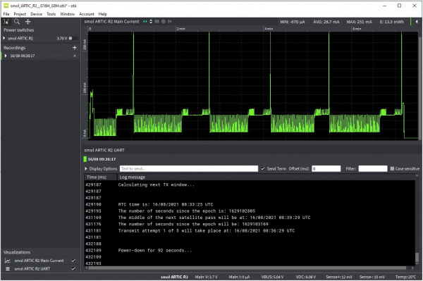
The picture below shows the current draw captured by Otii Arc for a complete transmit cycle using this example. The gain here is set to maximum.
At the start of the transmit cycle, the ESP32 Processor Board is woken up by the Power Board. It turns on the ZOE-M8Q GNSS board and waits for a fix. The current draw here is approximately 100mA for ~10 seconds.
Once the ESP32 has a location fix, it can calculate the time of the next ARGOS satellite pass. The power board woke the ESP32 up 1 minute before the start of the next pass, so the ESP32 goes in and out of light sleep for the next ~30 seconds.
The ARTIC R2 is powered on at the 40 second mark and the first of five transmits takes place just after the one minute mark.
The code example transmits five times on each satellite pass. The gap between the transmits is 90 seconds with a mandatory ±10% jitter. In between, you can see the ESP32 going in and out of light sleep with the ARTIC R2 being powered up 20-30 seconds before the next transmit is due.
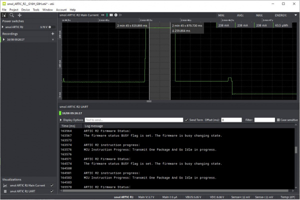
The phenomenal data captured by Otii Arc allows us to zoom right in on the transmit itself and capture the true maximum current draw:
It's then child's play to extract the data we need!
- LiPo Battery Voltage: 3.7V
- Peak Current Draw ESP32 + ARTIC R2 (maximum gain): 238mA
- Peak Current Draw ESP32 + ARTIC R2 (minimum gain): 114mA
- Average Current Draw during a complete 5*TX transmit cycle (maximum gain): 29.9mA
- Average Current Draw during a complete 5*TX transmit cycle (minimum gain): 24.9mA
- Average continuous ESP32 + ZOE-M8Q GNSS Current Draw: 97mA
- Current Draw during deep sleep: 6.4µA
- Power Consumption during a complete 5*TX transmit cycle (maximum gain): 13.3mWh
- Power Consumption during a complete 5*TX transmit cycle (minimum gain): 11.1mWh
We can then use this data to predict the battery life based on the transmit power and the number of transmissions per day. The satellite pass-prediction code in our Arduino Library can calculate the timing of the satellite passes with the highest elevation each day to maximize the chance of the transmission being received. Transmitting five times per day at maximum power, we could expect our very modest 400mAh battery to last over 100 days!
Resources and Going Further
Check out the individual board hookup guides for more information:
- Whether it's for assembling a kit, hacking an enclosure, or creating your own parts; the DIY skill is all about knowing how to use tools and the techniques associated with them.
- If it requires power, you need to know how much, what all the pins do, and how to hook it up. You may need to reference datasheets, schematics, and know the ins and outs of electronics.
