smôl ESP32 Hookup Guide
 PaulZC
 Introduction
smôl is a new board format and, as the name suggests, they're really small!
smôl ESP32
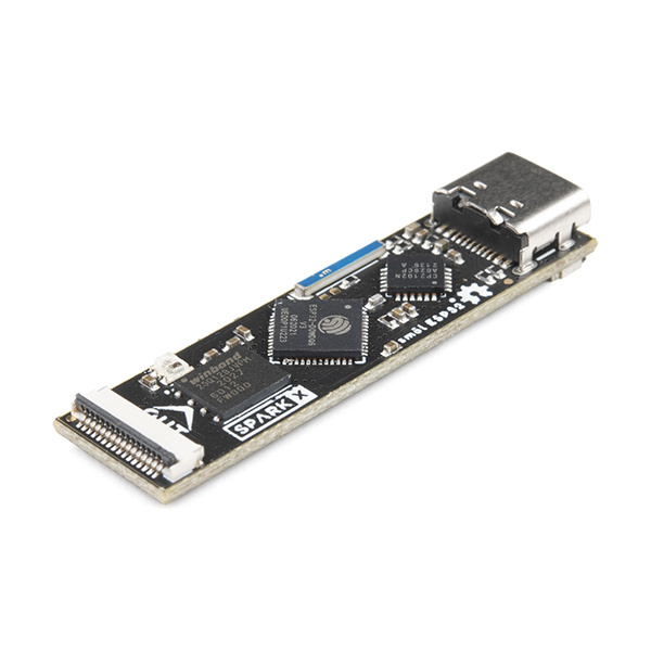
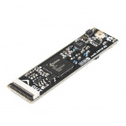
SPX-18619The smôl ESP32 is a Processor Board for smôl, based on the excellent Espressif ESP32 processor.
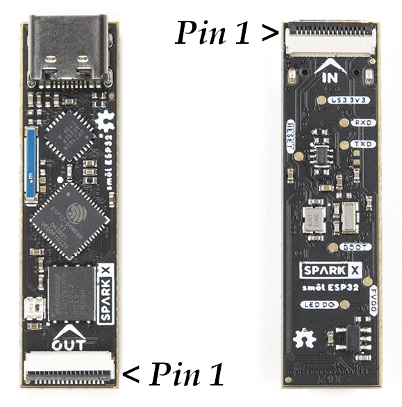
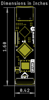
Each smôl board measures just 1.60" by 0.42" (40.6mm by 10.7mm). We made the boards just wide enough so we could squeeze USB-C and 16-way Flexible Printed Circuit (FPC) connectors on there. Some of the boards have components on both top and bottom layers which again helps keep the boards small.
smôl boards are designed to stack one on top of the other, using 16-way 0.5mm-pitch FPCs to provide the interconnect from one board to the next. Each board has an IN FPC connector on the bottom layer and an OUT FPC connector on the top layer. The boards stack in a zig-zag daisy chain; signals and power are passed from one board to the next up and down the chain through the FPCs.
Required Materials
As a minimum, you're going to need a USB-C cable to connect your smôl ESP32 to your computer:


The ESP32 Processor Board is part of the smôl ecosystem. Why not pair it with one of the smôl Peripheral Boards?
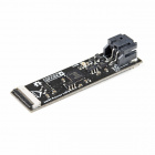
smôl ARTIC R2
SPX-18618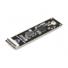
smôl ZOE-M8Q
SPX-18623To be able to reduce the sleep current below 10µA, you're going to want to pair the ESP32 with one of our intelligent smôl Power Boards:
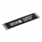
Don't forget that you will need Flexible Printed Circuits to connect your smôl boards together. You're going to need one FPC per board. Our 36mm FPC is the perfect length if you want the smôl boards to stack neatly, one on top of the other.
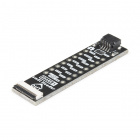
Need to do some prototyping with smôl? Or want to connect standard SPI or Qwiic (I2C) boards to your stack? The smôl Header is perfect for that:
Suggested Reading
This is the hookup guide for the smôl ESP32 Processor Board. Click the button below if you want to find out more about smôl itself.
We recommend taking a look through the following tutorials if you are not familiar with the concepts covered in them:
Serial Peripheral Interface (SPI)
I2C
Hardware Overview
In this section we'll cover what's included on the smôl ESP32 Processor Board.
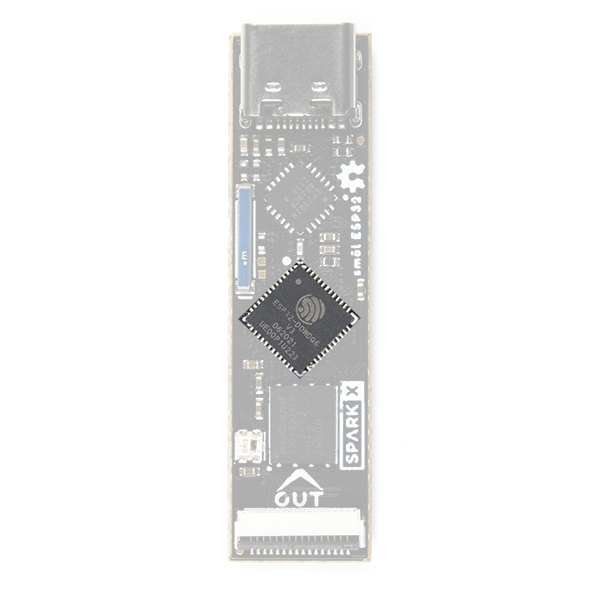
Espressif ESP32
Ahhh, the Espressif ESP32. It's one of the most unique microcontrollers on the market. In it's native form, it has a laundry list of features. On the smôl Processor Board, we include the following:
- Dual-core Tensilica LX6 microprocessor
- Up to 240MHz clock frequency
- 520kB internal SRAM
- Integrated 802.11 B/G/N WiFi transceiver
- Hardware accelerated encryption (AES, SHA2, ECC, RSA-4096)
- 16MByte Flash Storage
- Typical current draw: from USB (5V); using on-board regulator; CP210x active:
- SimpleWiFiServer (receive): 64.7mA (AVG); 59.1mA (MIN); 144mA (MAX)
- SPIFFS_Test (writing): 87.4mA (AVG)
- Light sleep: 11.1mA (AVG)
- Deep sleep: 9.6mA (AVG)
- Typical current draw: from smôl 3.3V; on-board regulator disabled; CP210x inactive:
- SimpleWiFiServer (receive): 63.6mA (AVG); 58.5mA (MIN); 142mA (MAX)
- SPIFFS_Test (writing): 74.9mA (AVG)
- Light sleep: 1.4mA (AVG)
- Deep sleep: 450µA (AVG)
- The sleep current can be reduced to less than 10µA by pairing the smôl ESP32 with one of our intelligent Power Boards
WS2812C RGB Status LED
We've included a miniature WS2812C RGB LED for visual status feedback:
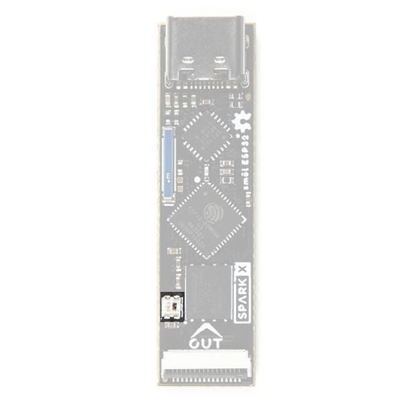
Wireless Antenna
Need wireless? The Espressif chip provides a WiFi transceiver which sends and receives data through a 2.4GHz Antenna.
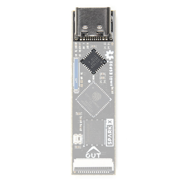
USB-C Connector and CP210x USB Interface
The USB-C connector allows you to connect the smôl ESP32 to your computer for programming and diagnostics.
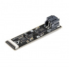
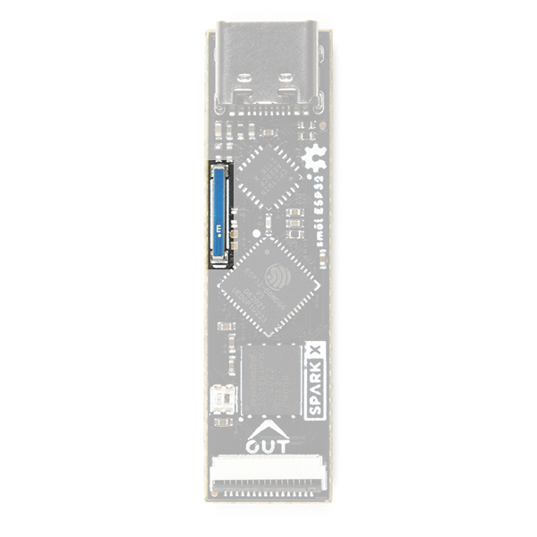
FPC Connections
Like all of our smôl boards, the ESP32 Processor Board is equipped with two 16-way 0.5mm-pitch Flexible Printed Circuit connectors. FPCs are used to link the smôl boards together in a daisy-chain.
The pin-out for the smôl ESP32 is as follows:
| Connector Pin No. | Signal Name | Function | Arduino Digital Pin No. |
|---|---|---|---|
| 1 | PROC_PWR_EN | Processor Power Enable | N/A |
| 2 | 3V3 | 3.3V Power Rail | N/A |
| 3 | GND | Power Ground / 0V | N/A |
| 4 | SCLK | SPI Clock | 18 |
| 5 | COPI | SPI Controller Out Peripheral In | 23 |
| 6 | CIPO | SPI Controller In Peripheral Out | 19 |
| 7 | CS0 | SPI Chip Select 0 | 5 |
| 8 | CS1 | SPI Chip Select 1 | 14 |
| 9 | CS2 | SPI Chip Select 2 | 13 |
| 10 | GPIO0 | General Purpose Input / Output 0 | 27 |
| 11 | GPIO1 | General Purpose Input / Output 1 | 26 |
| 12 | SDA | I2C Data | 21 |
| 13 | SCL | I2C Clock | 22 |
| 14 | GND | Power Ground / 0V | N/A |
| 15 | 3V3 | 3.3V Power Rail | N/A |
| 16 | V_USB | USB Power Rail (5V) | N/A |
The IN and OUT pin connections are identical on the smôl ESP32. (That's not always true on smôl Peripheral Boards. Check the Peripheral Board Hookup Guide for full details.)
We use a technique called waterfalling on the SPI Chip Select and GPIO signals. If you haven't used waterfalling before, please check out the smôl Hookup Guide.
The smôl ESP32 has an on-board 3.3V regulator for stand-alone use, powered by 5V from the USB-C connector. The PROC_PWR_EN signal allows a smôl Power Board to disable the Processor Board regulator. Please see the smôl Hookup Guide for more details.
Software Setup and Programming
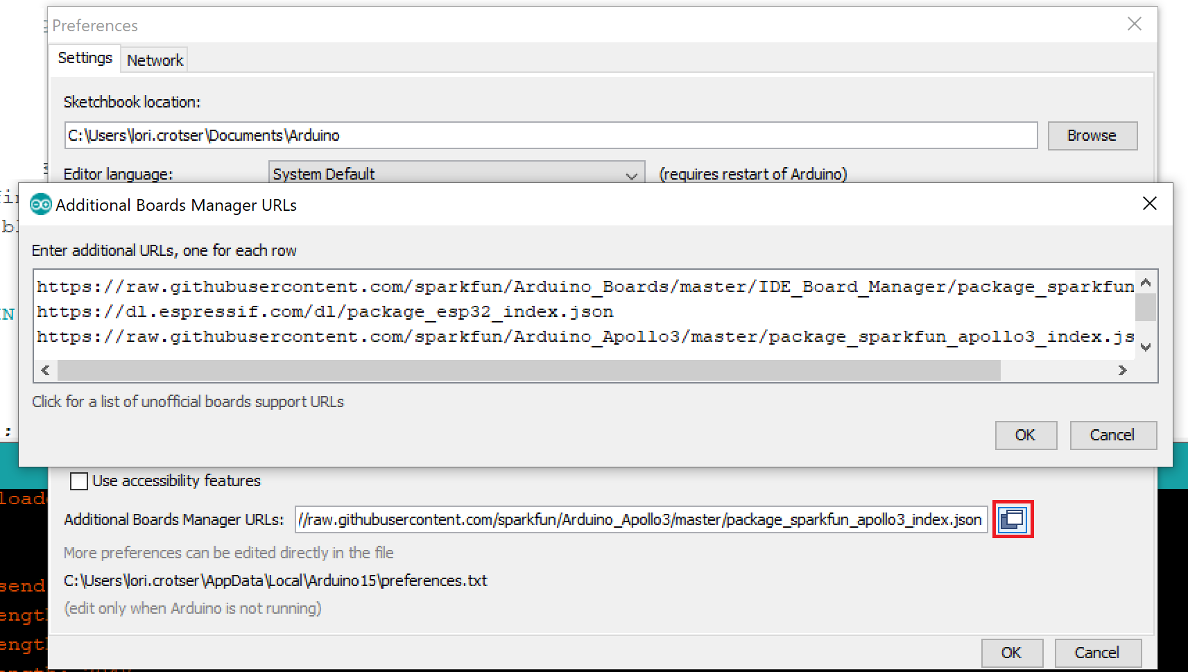
To get started with the smôl ESP32 Processor Board, you'll need to install the ESP32 Board Definition. Open the Arduino IDE (must be v1.8.13 or later) and navigate to File->Preferences, like so:

In the "Additional Board Manager URL" box, make sure you have the following two json files included. If you do not have them, add them to your preferences.
language:c
https://raw.githubusercontent.com/espressif/arduino-esp32/gh-pages/package_esp32_index.json
https://raw.githubusercontent.com/sparkfun/Arduino_Boards/main/IDE_Board_Manager/package_sparkfun_index.json
If you have more than one json file, you can click on the button outlined in red and add the json links at the end. It'll look something like the following:
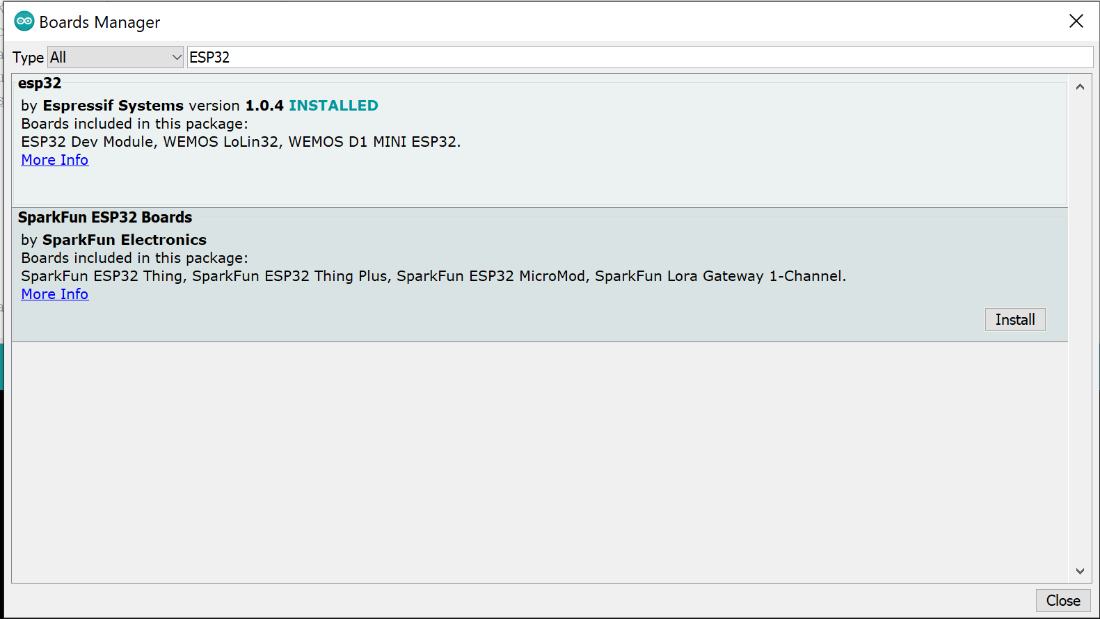
Once you've got your preferences updated, go to Tools -> Board and select the Boards Manager like so:

Search for "ESP32", and you should find both the esp32 and SparkFun ESP32 Boards board packages. Make sure the latest version selected and click Install for the esp32 boards. Repeat for the SparkFun ESP32 Boards.
Once the board definitions have been installed, you should see the SparkFun ESP32 Thing Board under your Tools -> Board -> SparkFun ESP32 Arduino menu. The smôl ESP32 uses the same board definition as the SparkFun ESP32 Thing; select that (and ignore the Thing Plus, MicroMod and LoRa Gateway options).

Voila! You're ready to rock with your smôl ESP32 Processor Board!
Arduino Example: RGB_LED
With the SparkFun ESP32 Arduino core installed, you're ready to begin programming. Make sure you have the ESP32 Thing definition selected under your Tools > Board menu, then it is time to connect your smôl ESP32 to your computer using a USB-C cable.
Next, select your serial port under the Tools > Port menu.
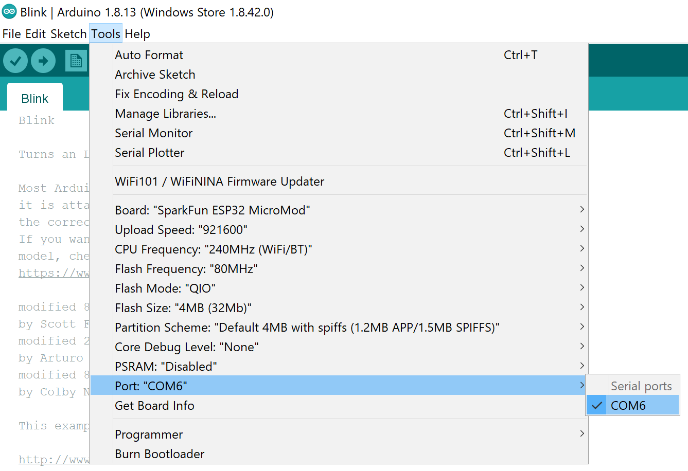
You can also select the Upload Speed: "921600" baud -- the fastest selectable rate -- will get the code loaded onto your ESP32 the fastest, but may fail to upload once-in-a-while. (It's still way worth it for the speed increase!)
Loading the RGB_LED Demo
To make sure your toolchain and board are properly set up, we'll upload a simple sketch -- RGB_LED! The WS2812C LED on the ESP32 Processor Board is perfect for this test. Copy and paste the example sketch below into a fresh Arduino sketch:
language:c
// smôl ESP32 LED Demo
//
// Select SparkFun ESP32 Thing as the board
//
// Make sure you have the correct drivers installed for the Silicon Labs
// CP210x USB to UART Bridge otherwise the automatic upload may fail
// https://www.silabs.com/developers/usb-to-uart-bridge-vcp-drivers

#include <FastLED.h> // http://librarymanager/All#FastLED

#define LED_PIN     25 //GPIO25 on smôl ESP32 is connected to WS2812 LED
#define COLOR_ORDER GRB
#define CHIPSET     WS2812
#define NUM_LEDS    1

#define BRIGHTNESS  50

CRGB leds[NUM_LEDS];

uint8_t gHue = 0; // rotating "base color" used by many of the patterns

void setup() {
    delay(30); // sanity delay
    FastLED.addLeds<CHIPSET, LED_PIN, COLOR_ORDER>(leds, NUM_LEDS).setCorrection( TypicalLEDStrip );
    FastLED.setBrightness( BRIGHTNESS );
}

void loop()
{
  fill_rainbow( leds, NUM_LEDS, gHue, 7);
  FastLED.show();

  EVERY_N_MILLISECONDS( 10 ) { gHue++; } // cycle the "base color" through the rainbow
}
With everything set up correctly, click the arrow icon to upload the code! Once the code finishes transferring, the RGB LED should start cycling through all the colors of the rainbow. Hypnotic isn't it?!
Troubleshooting
If you haven't used the fantastic FastLED library before, you will need to install it through the IDE Library Manager. The easiest way to do that is to click the link next to the #include <FastLED.h>. When the Library Manager has finished searching, select the latest version of FastLED and click Install.
If the code fails to upload when you click the upload (arrow) icon, check you have the correct port selected and have the official CP210x driver installed. If you're trying to use a generic USB driver, it won't be able to initialize the Bootloader via DTR and RTS pins.
Further Examples
You can find more tried-and-tested examples in the GitHub repo:
- SPIFFS_Test will format part of the Processor Board's flash memory as an SPI Flash File System and check it is working correctly by creating, editing, renaming and deleting a text file
- SimpleWiFiServer is a fun little demo:
- Edit the code and replace
yourssidandyourpasswdwith the name and password of your WiFi network - Upload the code and open the Arduino IDE Tools > Serial Monitor at 115200 baud to see the diagnostic messages
- Make a note of the smôl ESP32's IP Address
- Open a web browser on your computer and open the web page at
http://nnn.nnn.nnn.nnnwhere nnn.nnn.nnn.nnn is the smôl ESP32's IP address - Click the web page buttons to change the color of the RGB LED
- Edit the code and replace
Troubleshooting
Resources and Going Further
For more information about the smôl ESP32 Processor Board, check out the following links:
- Schematic
- Eagle Files
- Board Dimensions
- Datasheet (ESP32-D0WDQ6-V3)
- GitHub Hardware Repo
- Arduino Examples