MicroMod WiFi Function Board - DA16200 Hookup Guide
Hardware Overview
DA16200
The MicroMod WiFi Function Board includes the DA16200 module from Dialog with AT command firmware. This chip is a fully integrated Wi-Fi® module with ultra-low power consumption, 40 MHz crystal oscillator, 32.768 KHz RTC clock, RF Lumped RF filter, 4 M-byte flash memory, and an onboard chip antenna. For more information, refer to the datasheet.

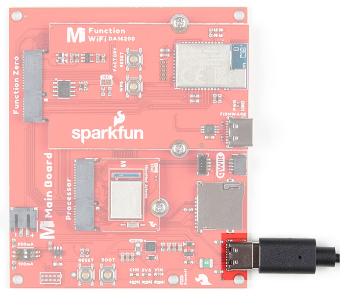
Power
To power the board, you will need to apply power to a SparkFun Main Board; either a Single or a Double. Power applied will connect to the Function Board's VIN pin, which will be regulated down for the rest of the board with the AP2112 3.3V/600mA voltage regulator.
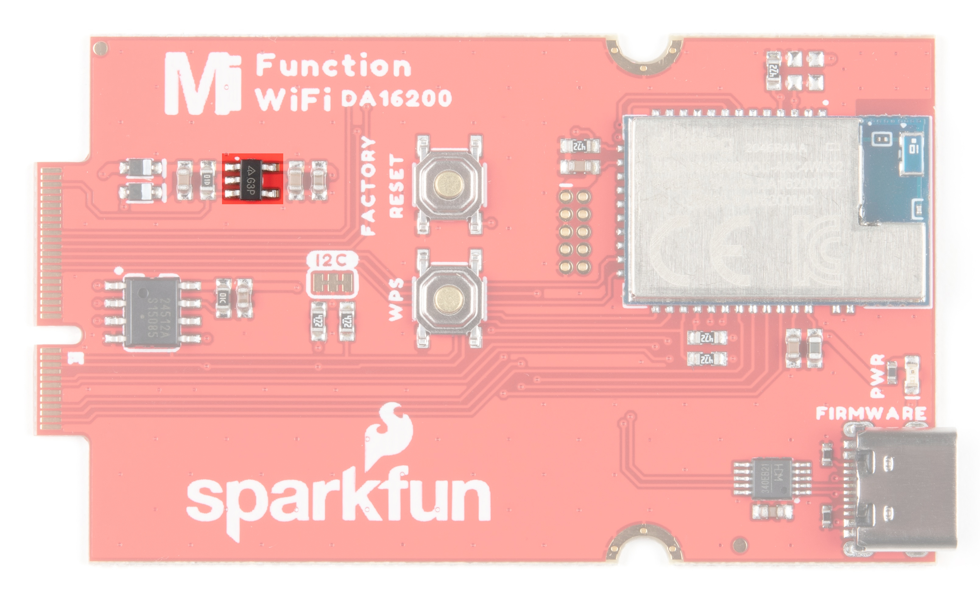
AP2112
Operating voltage for the DA16200 is 3.3 V. The AP2112 can handle a voltage range of 2.5-6V with a 600mA output and ensures appropriate voltage to the WiFi unit.
CH340
The board is populated with the CH340E USB-to-Serial converter to update firmware on the DA16200 through its USB Type C connector. You will need a Main Board and a second USB cable to update the firmware.

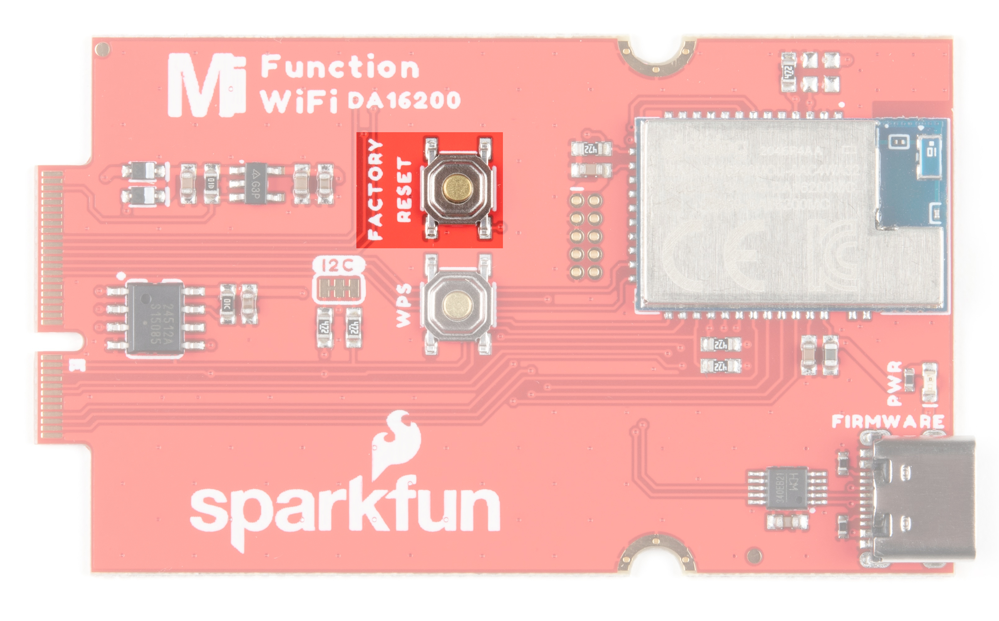
Reset Button
The reset button allows users to reset the program running on the Dialog module without unplugging the board.
WPS Button
The Wi-Fi Protected Setup Button allows you to easily and quickly connect to a WiFi network.

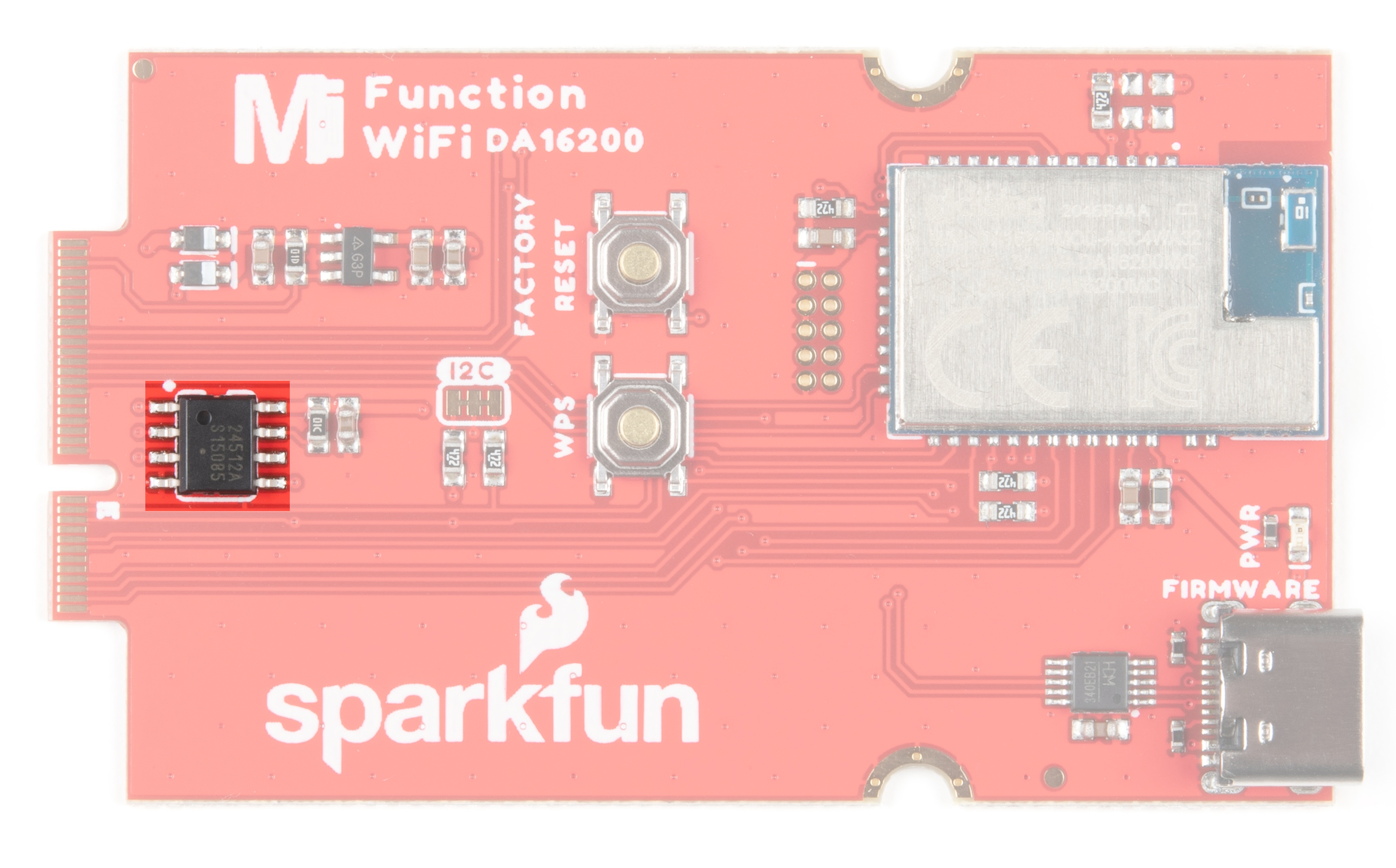
EEPROM
The board includes an I2C EEPROM. To enable writing to the EEPROM, pull WP low, either through the EEPROM_WP pin or by closing JP3.
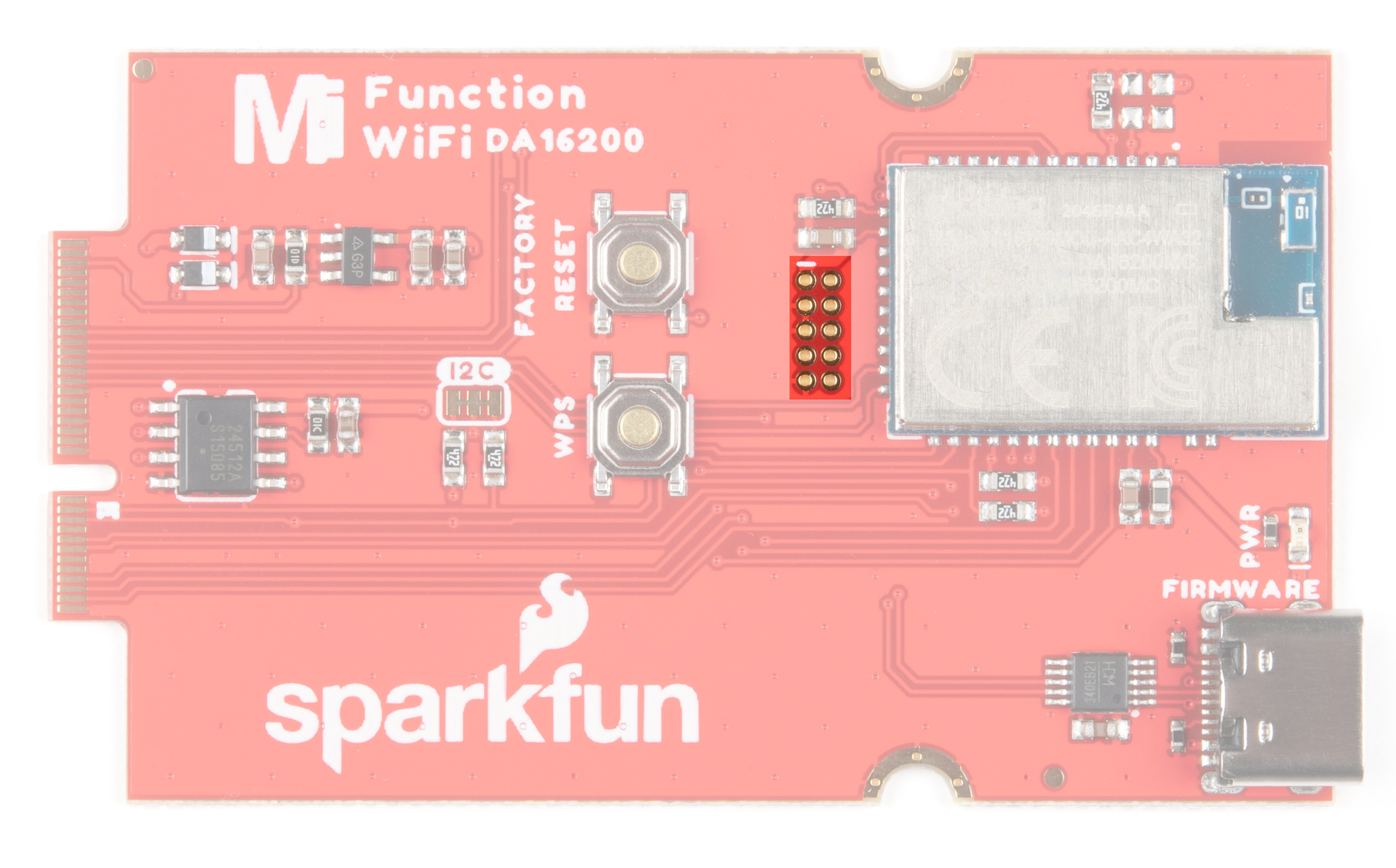
JTAG
An unpopulated JTAG footprint is available for more advanced users who need breakpoint level debugging. We recommend checking out our JTAG section for the compatible male header and a compatible JTAG programmer and debugger.
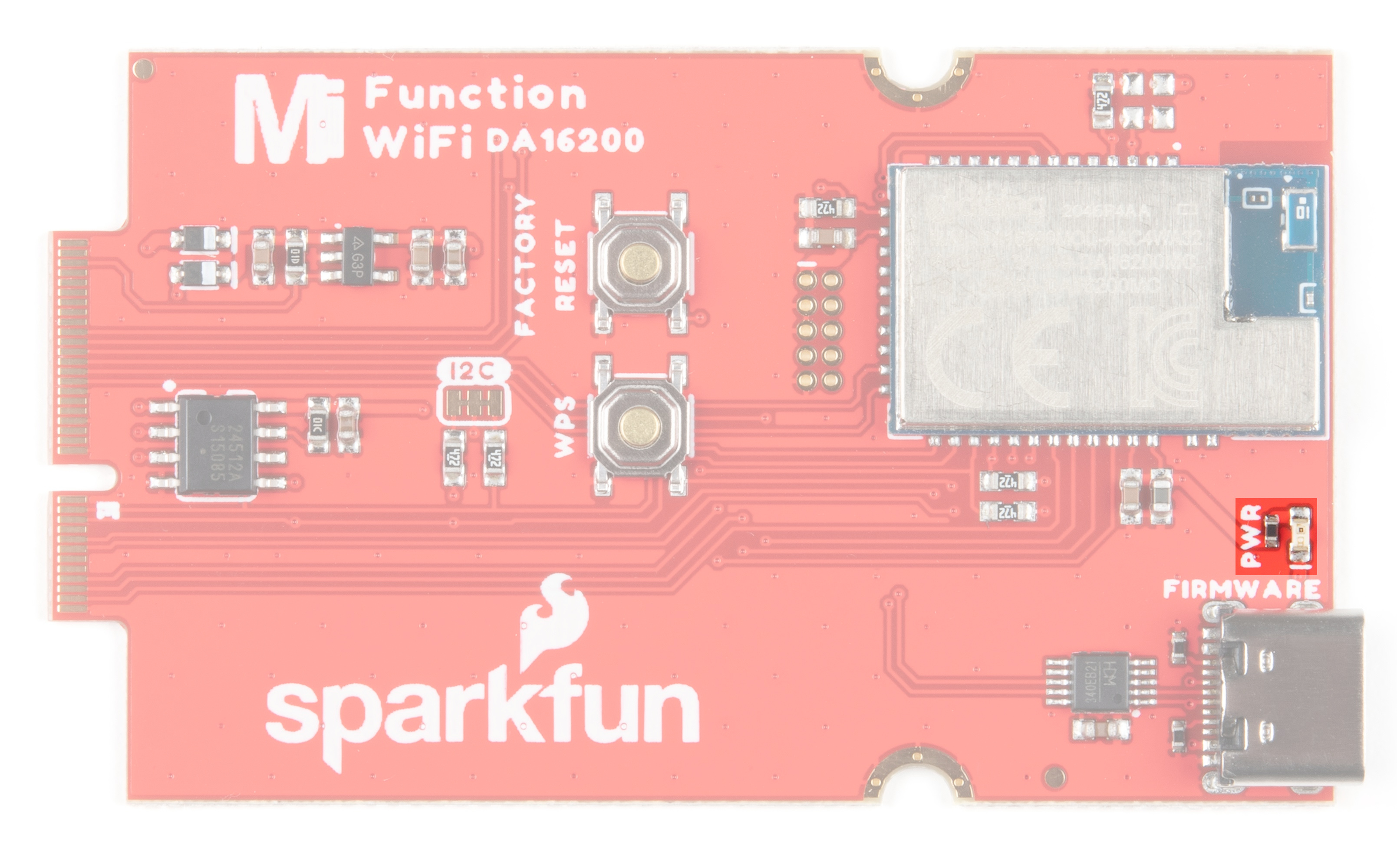
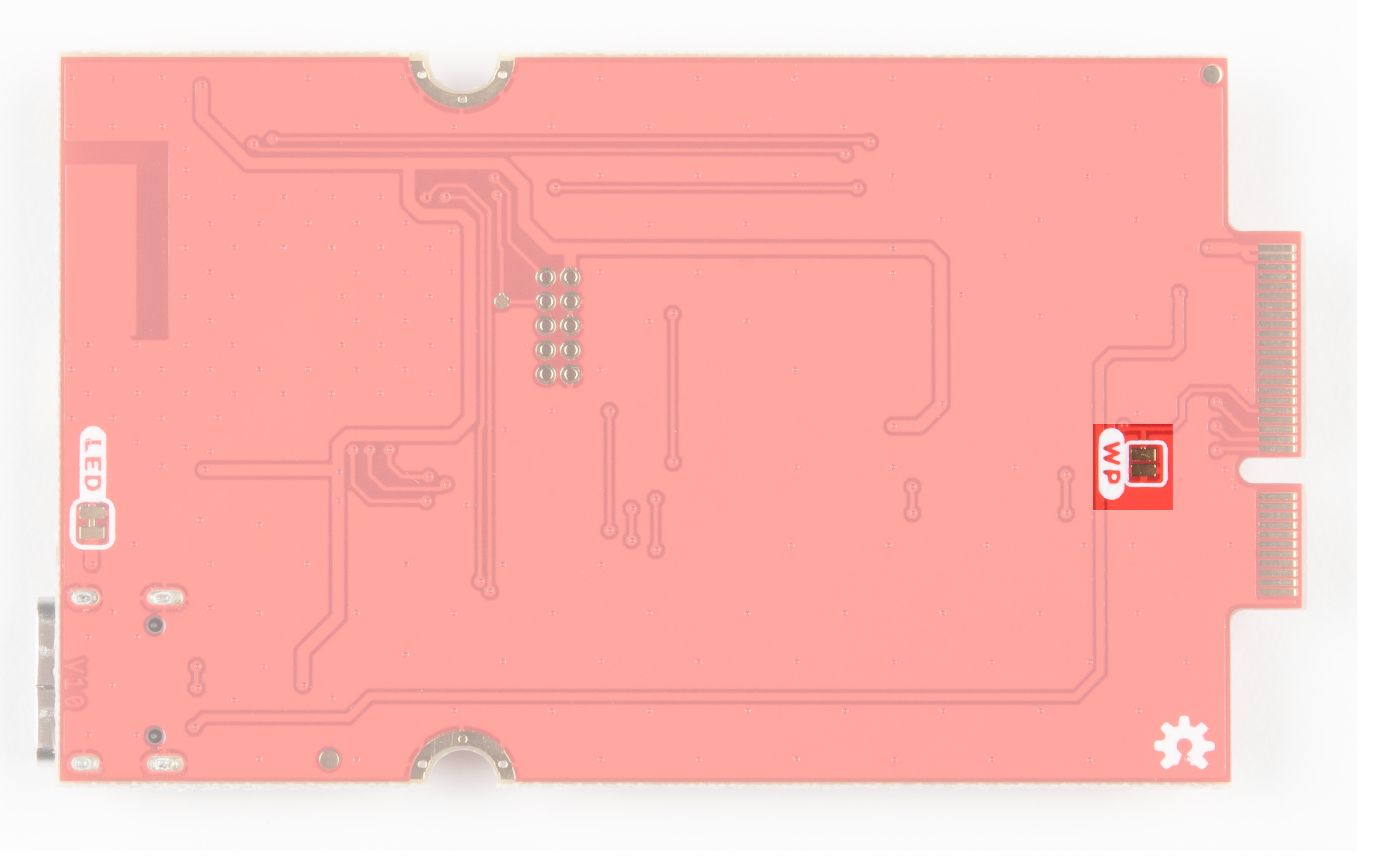
LED
There is only one LED available which is the Power LED. The LED lights up to indicate availability for the DA16200 from the 3.3V voltage regulator. You can disable it by cutting the jumper on the back of the board (see Jumpers below).
Jumpers
The following jumpers are included to configure the board.
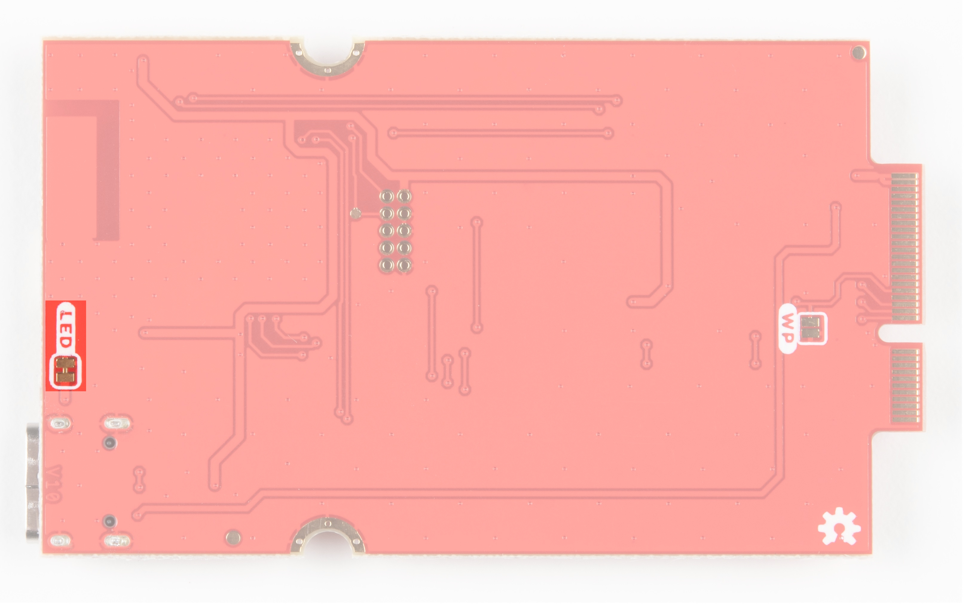
- PWR - By default, the jumper with the label
PWRis closed. This jumper connects the 3.3V line and LED. Cutting this jumper will disable the LED.
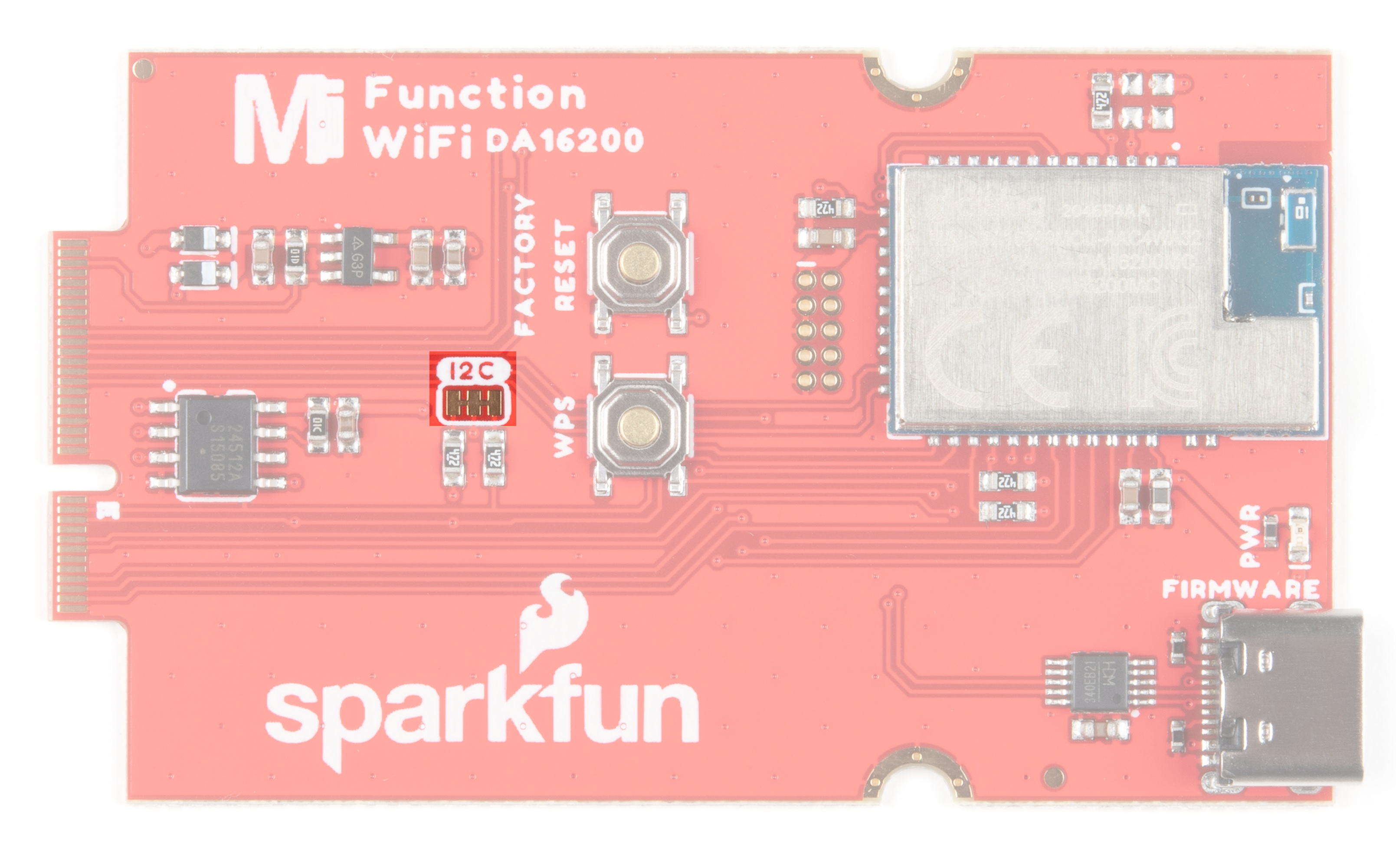
- I2C Pull-up Resistors - By default, this three way jumper labeled
I2Cis closed and connects two pull-up resistors to the I2C data lines. If you have many devices on your I2C data lines, then you may consider cutting these two jumpers.
- WP - By default, write protect for the EEPROM is on. To disable write protection, close this jumper.
Hardware Pinout
The M.2 connector on the MicroMod WiFi Function Board - DA16200 is routed according to the pinout chart below:
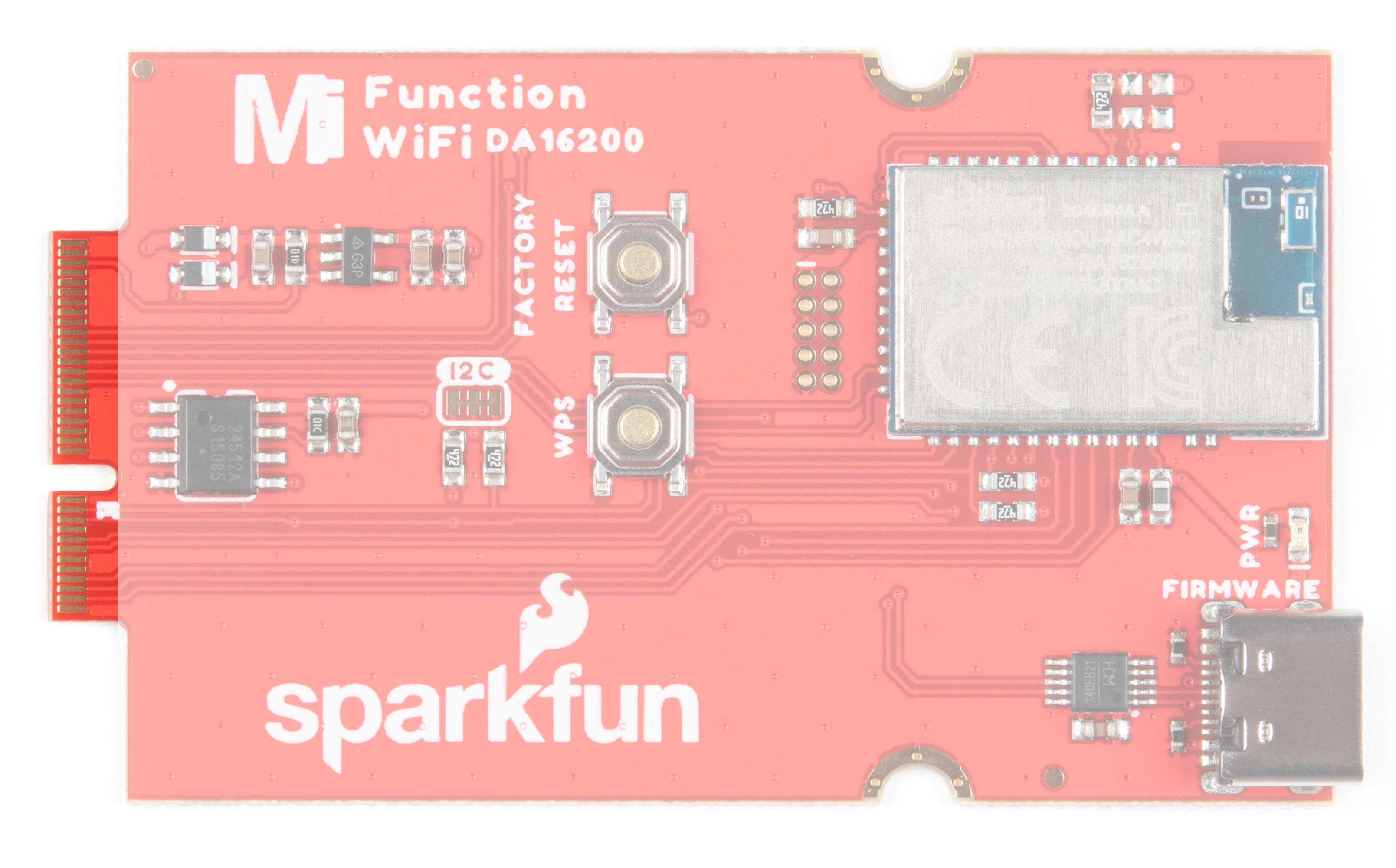
Depending on your window size, you may need to use the horizontal scroll bar at the bottom of the table to view the additional pin functions. Note that the M.2 connector pins on opposing sides are offset from each other as indicated by the bottom pins where it says (Not Connected)*. There is no connection to pins that have a "-" under the primary function.
| AUDIO | UART | GPIO/BUS | I2C | SDIO | SPI0 | Dedicated |
| Description | Function | Bottom Pin |
Top Pin |
Function | Description |
|---|---|---|---|---|---|
| (Not Connected) | 75 | GND | |||
| - | 74 | 73 | 3.3V | Power Supply: 3.3-6V | |
| - | 72 | 71 | Power EN | Power Supply: 3.3-6V | |
| - | 70 | 69 | - | ||
| - | 66 | 65 | - | ||
| - | 64 | 63 | - | ||
| - | 62 | 61 | - | ||
| - | 60 | 59 | - | ||
| - | 58 | 57 | RTC_WAKE1 | This pin is an input pin for receiving an external event signal from an external device like a sensor. The RTC block detects an external event signal via this pin and wakes up DA16200 from Sleep mode 2 or Sleep mode 3. | |
| - | 56 | 55 | RTC_WAKE2 | This pin is an input pin for receiving an external event signal from an external device like a sensor. The RTC block detects an external event signal via this pin and wakes up DA16200 from Sleep mode 2 or Sleep mode 3. | |
| - | 54 | 53 | RTC_PWR_KEY | Enable to kick off a predefined power-up sequence and eventually all the necessary power is supplied to all the sub-blocks including the main digital block in DA16200. When disabled, all blocks are powered off and this mode is defined as Sleep mode 1. | |
| - | 52 | 51 | GPIOA11 | ||
| - | 50 | 49 | CS | ||
| - | 48 | 47 | GPIOA10 | ||
| - | 46 | 45 | GND | ||
| - | 44 | 43 | - | ||
| - | 42 | 41 | - | ||
| Controls the write protection pin for the EEPROM. Pull low to enable. | EEPROM_WP | 40 | 39 | GND | |
| - | 38 | 37 | - | ||
| Controls EEPROM's I2C address configuration. | EEPROM_A0 | 36 | 35 | - | |
| Controls EEPROM's I2C address configuration. | EEPROM_A1 | 34 | 33 | GND | |
| Controls EEPROM's I2C address configuration. | EEPROM_A2 | 32 | 31 | Module Key | |
| Module Key | 30 | 29 | Module Key | ||
| Module Key | 28 | 27 | Module Key | ||
| Module Key | 26 | 25 | Module Key | ||
| Module Key | 24 | 23 | - | ||
| - | 22 | 21 | I2C_SCL | I2C - Clock signal for EEPROM | |
| - | 20 | 19 | I2C_SDA | I2C - Data signal for EEPROM | |
| - | 18 | 17 | - | ||
| - | 16 | 15 | U1_RXI | ||
| - | 14 | 13 | U1_TXO | ||
| - | 12 | 11 | - | ||
| - | 10 | 9 | - | ||
| - | 8 | 7 | CIPO | ||
| - | 6 | 5 | COPI | ||
| - | 4 | 3 | SCK | ||
| - | 2 | 1 | GND |
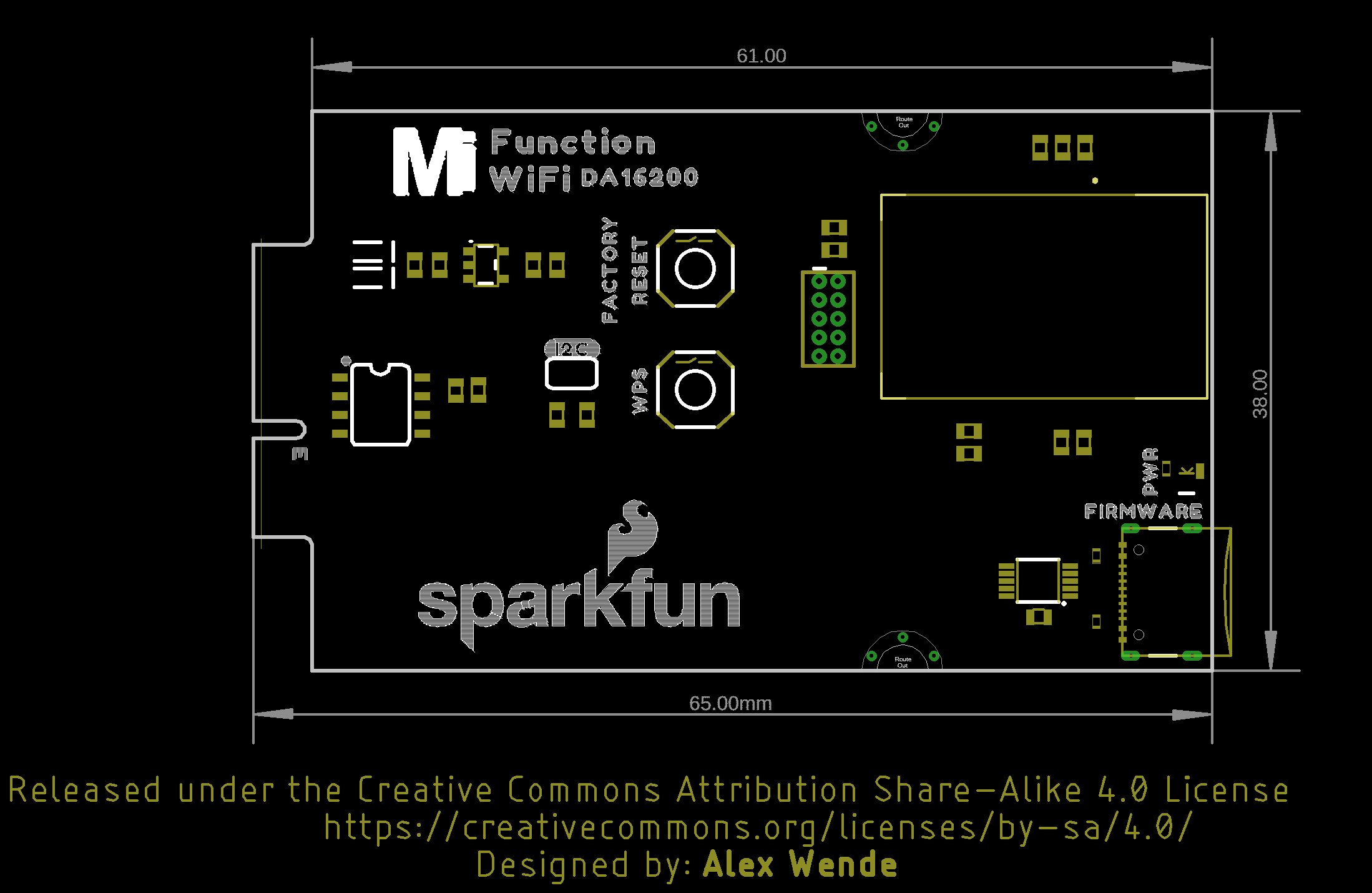
Board Dimensions
The board uses the standard MicroMod Function Board size which measures about 1.50"x2.56".