MicroMod WiFi Function Board - DA16200 Hookup Guide
Hardware Hookup
Adding a Processor Board to the Main Board
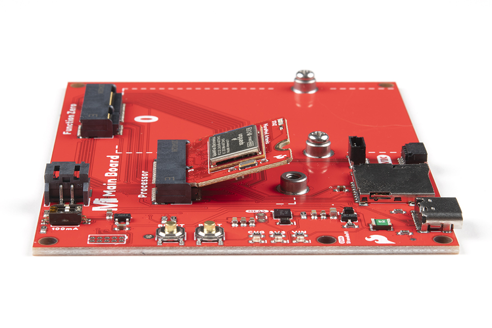
Align the top key of the MicroMod Artemis Processor Board to the Processor screw terminal of your Main Board and angle the board into the socket. Insert the board at an angle into the M.2 connector.
The Processor Board will stick up at an angle, as seen here:
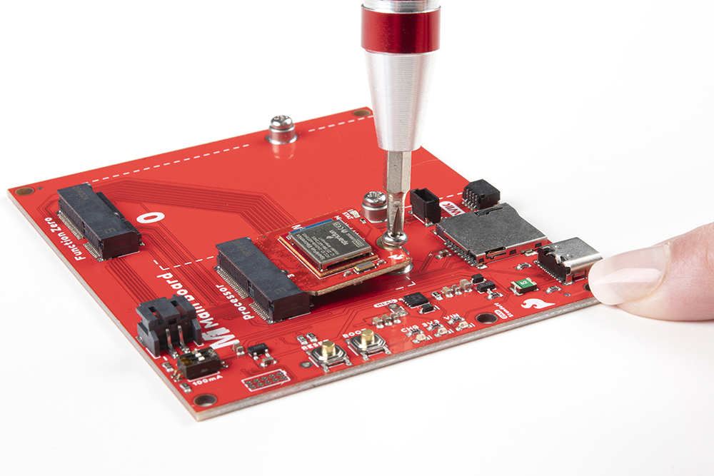
Once the board is in the socket, gently push the MicroMod Processor Board down and tighten the screw with a Phillip's head.
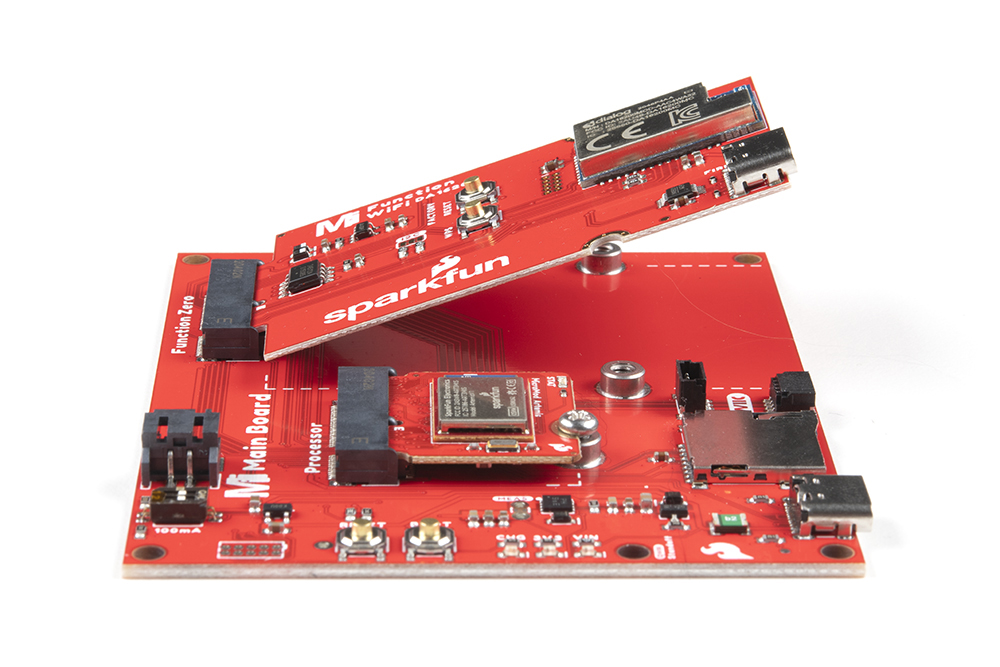
Adding a Function Board to the Main Board
As with the Processor Board, align the top key of the MicroMod WiFi Function Board to the screw terminal of your Main Board on the Function Board side and angle the board into the socket. Insert the board at an angle into the M.2 connector.
Once the board is in the socket, gently push the MicroMod Function Board down and tighten the screws with a Phillip's head.
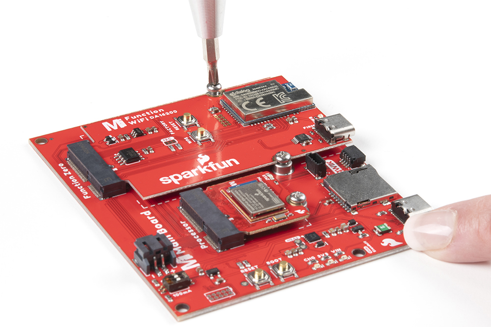
Once both boards are secure, your assembled MicroMod system should look similar to the image below!
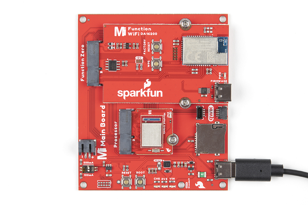
DA16200 Firmware Update
To update the firmware you will need to connect the USB C cable to the MicroMod WiFi Function Board (DA16200) to a computer's COM port. An additional Main Board with a second USB C cable is also needed to power the Main Board and MicroMod WiFi Function Board.
