MicroMod WiFi Function Board - DA16200 Hookup Guide
Contributors:
Ell C
Example 1: Basic Connection
Copy and paste the code below into a fresh Arduino sketch.
language:c
/******************************************************************************
  Example_01 Basic Connection

  Connect to the DA16200 Module
  Print help commands

  Development environment specifics:
  IDE: Arduino 1.8.13
  Hardware Platform: MicroMod Artemis Processor, Single MicroMod Main Board

  Hardware Connections:
  Connect the MicroMod Processor Board to the Processor M2 Connector of the Main Board
  Connect the MicroMod DA16200 Function Board to the Function M2 Connector of the Main Board

  G0      --> RTC_PWR_KEY
  4       --> PWR_EN
  3.3V    --> 3.3V
  GND     --> GND

  This program is distributed in the hope that it will be useful,
  but WITHOUT ANY WARRANTY; without even the implied warranty of
  MERCHANTABILITY or FITNESS FOR A PARTICULAR PURPOSE. See the
  GNU General Public License for more details.

  You should have received a copy of the GNU General Public License
  along with this program.  If not, see <http://www.gnu.org/licenses/>.
******************************************************************************/
#define PWR_EN 4
#define RTC_PWR_KEY G0

void setup() {
  pinMode(PWR_EN,OUTPUT);
  digitalWrite(PWR_EN,LOW);

  pinMode(RTC_PWR_KEY,OUTPUT);
  digitalWrite(RTC_PWR_KEY,LOW);

  Serial.begin(115200);
  Serial1.begin(115200);

  while(!Serial){

  }
  delay(1000);


  //Enable DA16200 Module RTC power block
  pinMode(PWR_EN,OUTPUT);
  digitalWrite(PWR_EN,LOW);

  pinMode(RTC_PWR_KEY,OUTPUT);
  digitalWrite(RTC_PWR_KEY,LOW);

  Serial.println("DA16200 AT Command example sending/receiving commands\n");
  while(!Serial){

  }

  pinMode(PWR_EN,INPUT);

  pinMode(RTC_PWR_KEY,OUTPUT);
  digitalWrite(RTC_PWR_KEY,HIGH);

  delay(2000);


  //Listen for ready message ("+INIT:DONE")
  byte count = 0;
  String msg = "";

  while(count<20)
  {
    delay(100);
    while(Serial1.available())
    {
      msg += char(Serial1.read());
    }
    if(msg.length() > 5) break;
    count++;
    delay(100);
  }
  msg = msg.substring(3,msg.length());

  if(msg.length()>5)
  {
    Serial.println("Expecting: \"INIT:DONE,(0 or 1)");
    Serial.println("Received: " + msg);
  }
  else
  {
    Serial.println("Failed to receive initialization message\n");

    Serial.println("Make sure the baud rate for Serial1 matches the baud rate\n" \
                   "saved to the DA16200. You can also perform a factory reset by\n" \
                   "pressing and holding the GPIOA7 button for ~5s, which will\n" \
                   "reset the baud rate back to 115200");
  }
    Serial.println("\nTry entering \"?\" or \"help\" to print out the list of AT commands\n" \
                 "\nIf the received text is unreadable, try changing the baud rate to\n" \
                 "9600 with the command \"ATB=9600\" in the terminal. Next, update the\n" \
                 "example code by setting Serial1 to 9600 baud and trying again.\n");
}

void loop() {
    while(Serial.available())
    {
      Serial1.print(char(Serial.read()));
    }

    while(Serial1.available())
    {
      Serial.print(char(Serial1.read()));
    }
}
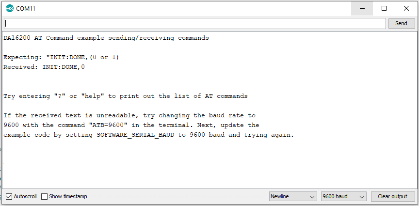
Set your Board and Serial Port, and then upload the sketch to your Arduino. Then open the serial monitor. Make sure your baud rate is set to 9600. You'll begin to see output.