micro:bot Kit Experiment Guide
 D___Run___,
  TheDarkSaint,
  bboyho, Ell C
 Experiment 3: Following a Line
Introduction
OK, you have your robot staying inside of box drawn on the floor, but that still seems a little odd and random. You want your robot to go somewhere, do something and then keep going! In this experiment, you will elaborate what you learned from Experiment 2 to get your robot to follow a line.
Parts Needed
You will need the following parts:
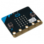
- 1x micro:bit board (Not Included with Kit)
- 1x Micro-B USB cable (Not Included with Kit)
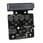
- 1x moto:bit Carrier Board
- 2x Wheels
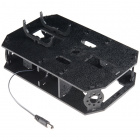
- 1x Assembled Shadow Chassis
- 2x Hobby Gear Motors
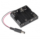
- 1x 4xAA Battery Holder
- 4x AA Batteries (Not Included with Kit)
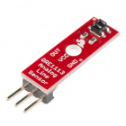
- 3x Analog Line Following Sensors
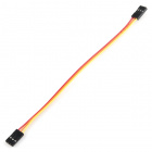
- 3x 3-Pin Jumper Wires
Didn’t get the kit? Have no fear! Here are the parts you will need to complete this experiment. You may not need everything though depending on what you have. Add it to your cart, read through the guide, and adjust the cart as necessary.


micro:bit Board
DEV-14208Suggested Reading
Getting Started with the micro:bit
Introduction to Using Multiple Line Sensors
In the previous experiment, you used a single line sensor (the middle sensor) to detect the line on the floor. That is great for staying inside of a line, but now, you need to follow a line. That is where the other two line sensors come in.

Essentially, you want the center sensor to detect the line, but not the other two, meaning that the robot is centered on the line. If one of the side sensors detect a line it means that you are veering to one side or another and your robot should correct itself. We will use the information from multiple sensors combined with an if/else statement block to build a decision tree for your robot to follow. For simplicity, we will start with using just two of the line sensors (the left and right sensors) to follow a dark black line. As you add more line following sensors to a robot, the code can get complex. However, the robot will able to follow a line better.
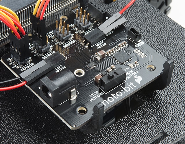
Hardware Hookup
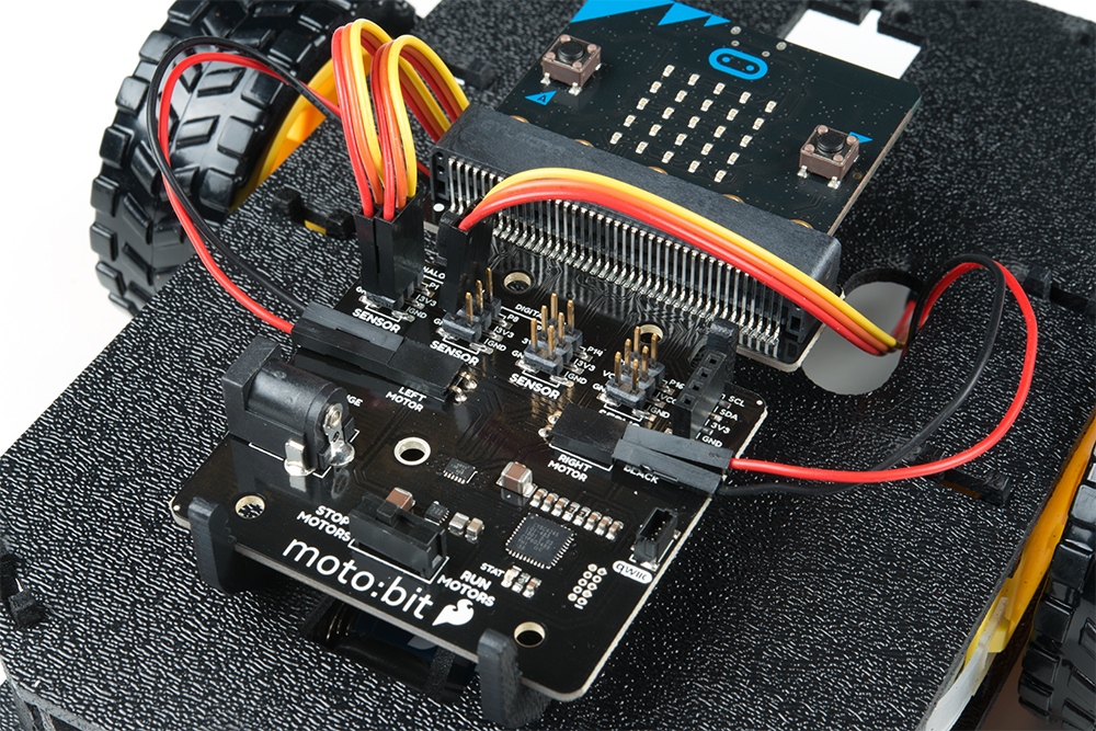
Like the motors, you should have already hooked up the line sensors during the assembly portion of this guide. You can go there now for the full assembly instructions. Double check to make sure that the wires are hooked up to your line sensors correctly!
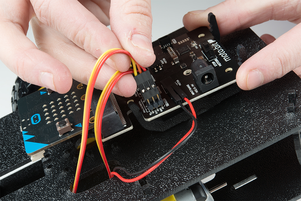

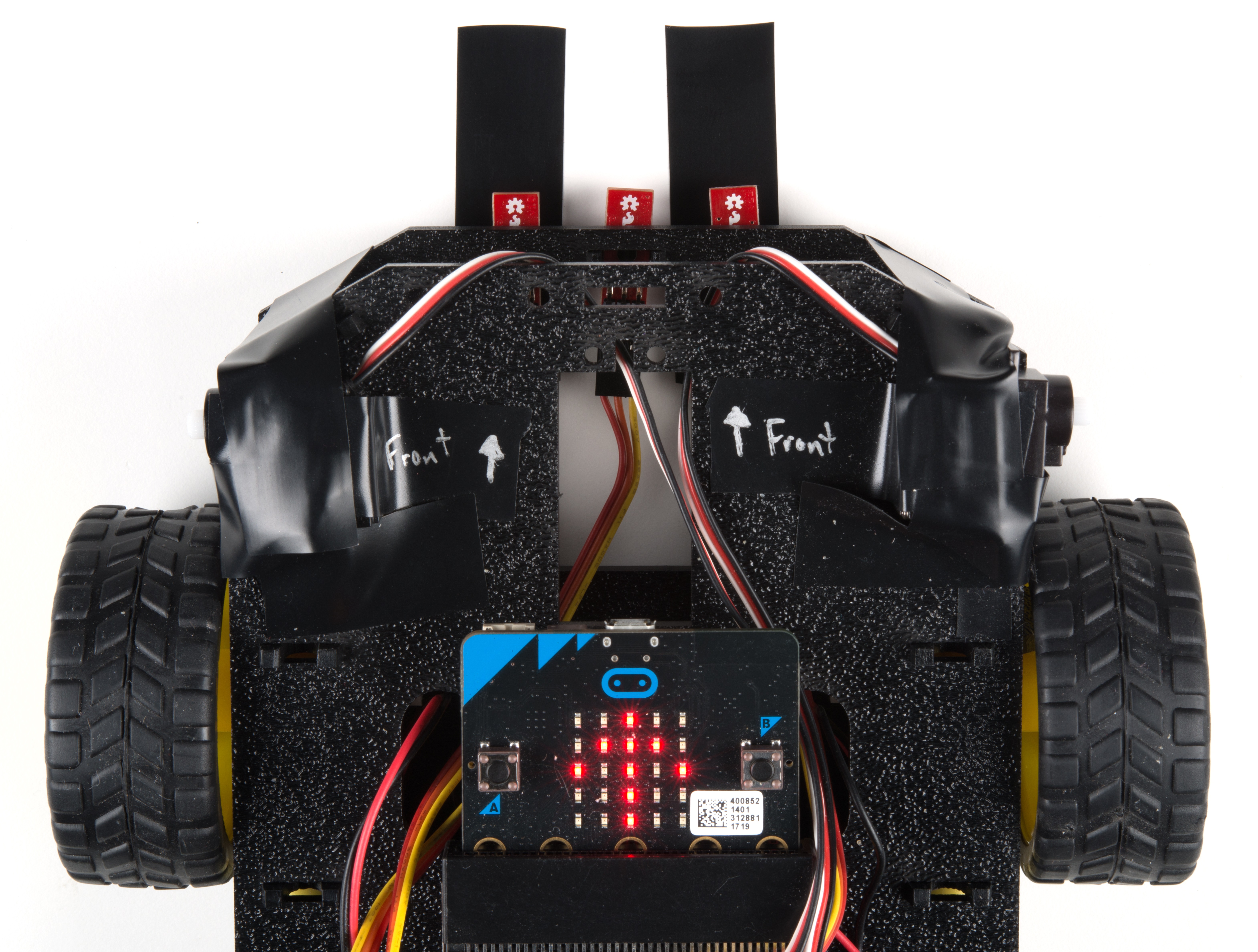
The line sensors hookup to your moto:bit via female / female jumper wires that snake through the chassis of your robot up to the moto:bit. The sensors hookup to the moto:bit in the following order:
- LEFT =>
PO - CENTER =>
P1 - RIGHT =>
P2
Double check to make sure they are hooked up correctly and in the proper orientation
Experiment 3a -- Simple IR Sensor Reading
Let's break up this experiment into two parts. First, we will have the micro:bot follow a straight dark, black line. Then we will have a slightly more complex path to try to have the micro:bot drive around a path with a zigzagged pattern.
Running Your Script
Be sure to add the moto:bit package as instructed in the Installing the moto:bit Package in MakeCode section of this tutorial.
Now, you can either download the following example script below and drag and drop it onto your micro:bit, or use it as an example and build it from scratch in MakeCode.
Code to Note
Let’s take a look at the code and what to expect.
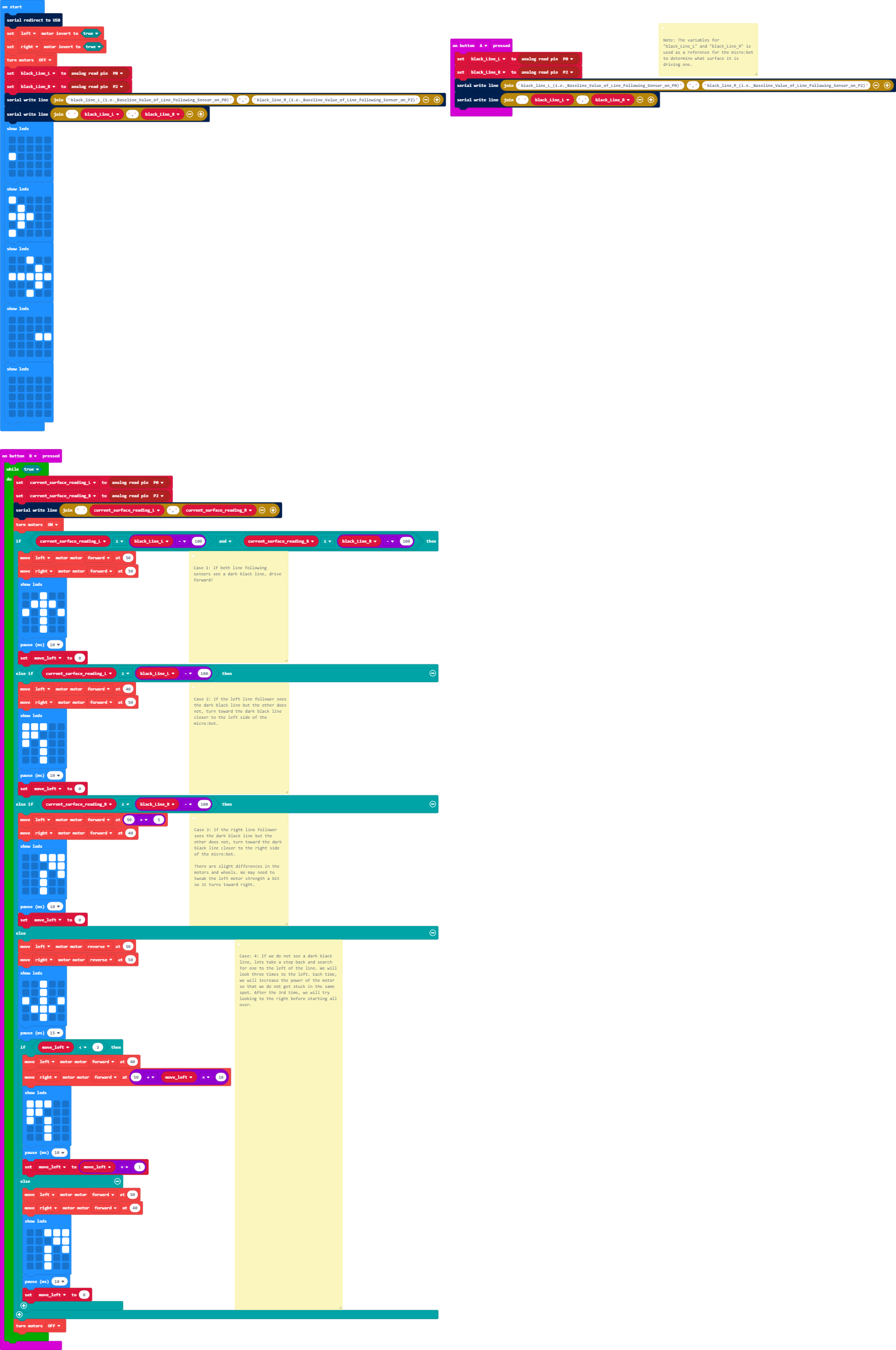
black_Line_L and black_Line_R
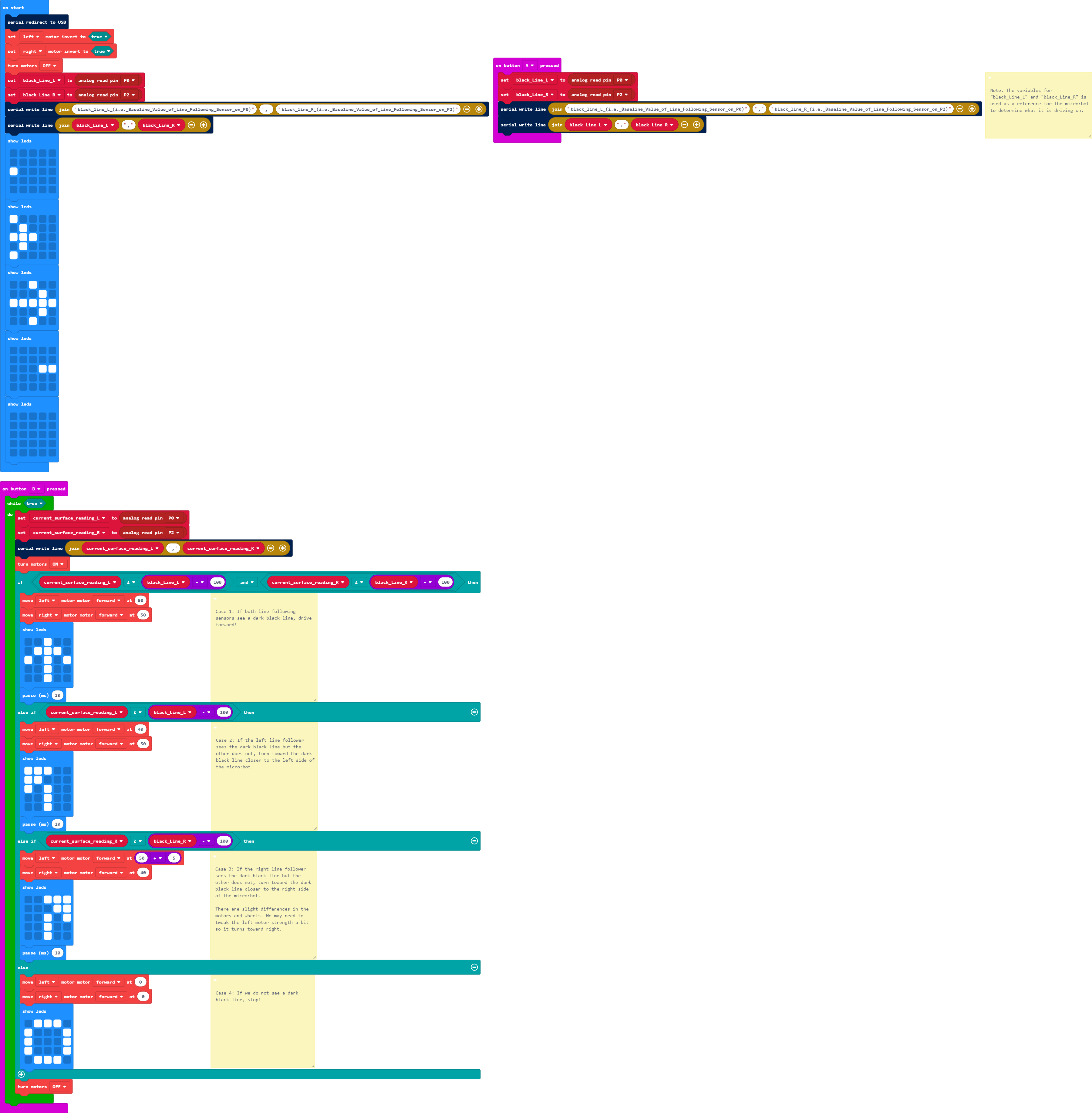
Like in the previous experiment, you need to set a baseline value for the surface that your robot is driving on. This is actually called a calibration value. We need to do this for two sensors now; left and right. We go through the same routine we did for the single sensor previously, but for the left and right sensors.
Comma Delimiter
For debugging, we set up the serial again. However, we will use the join block with a comma delimiter. This is useful for graphing more than one sensor readings.
On Button Press
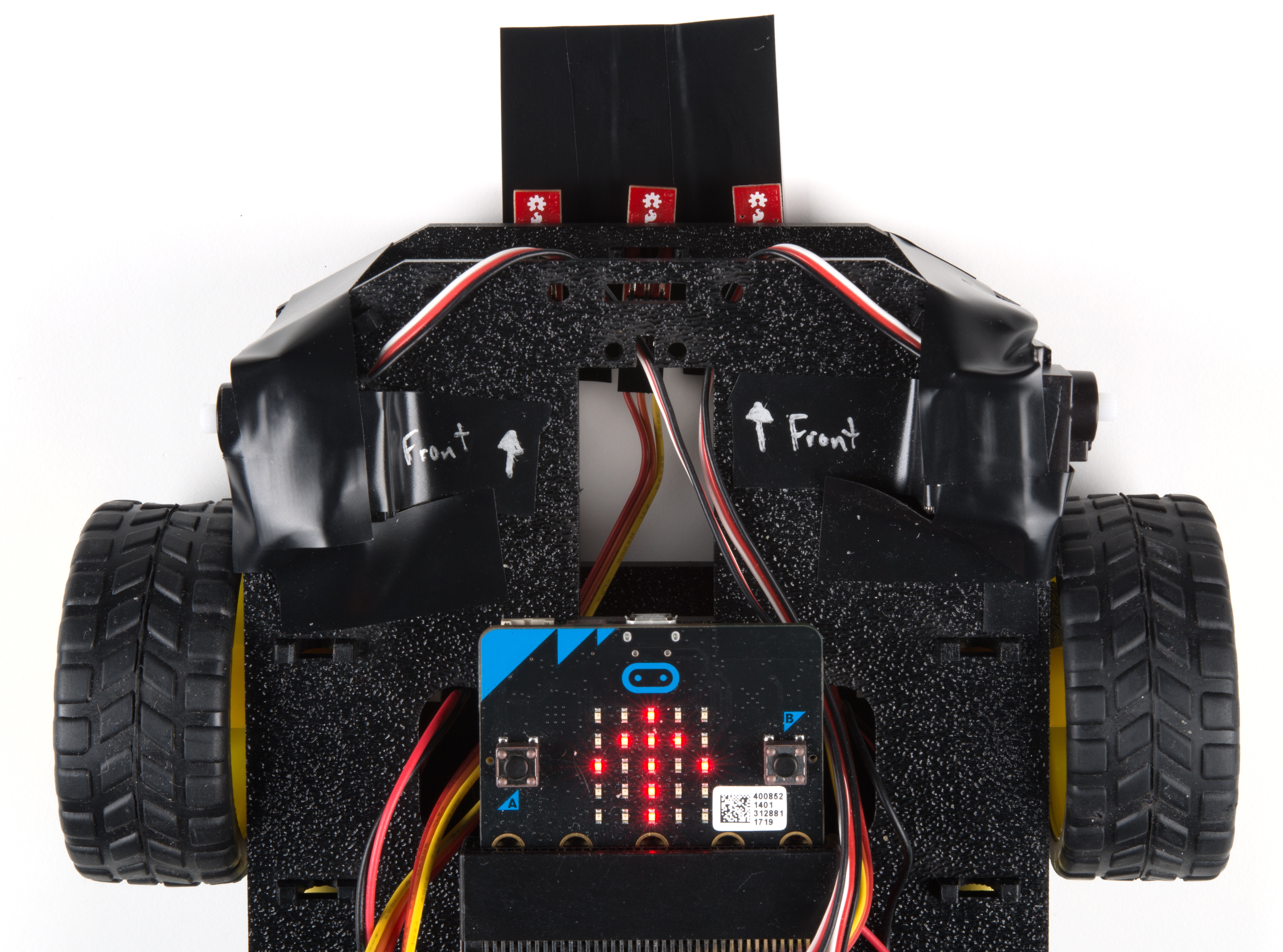
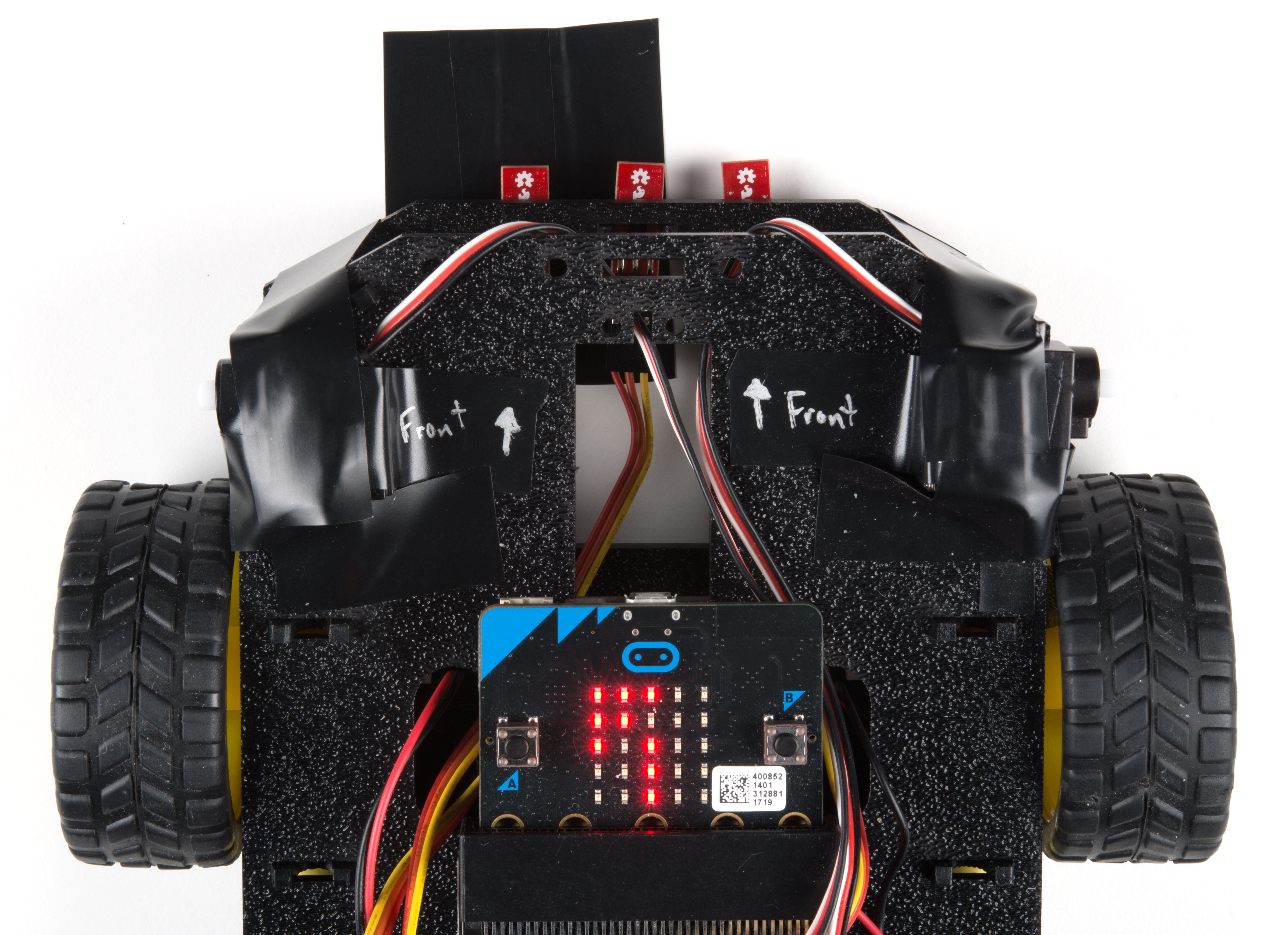
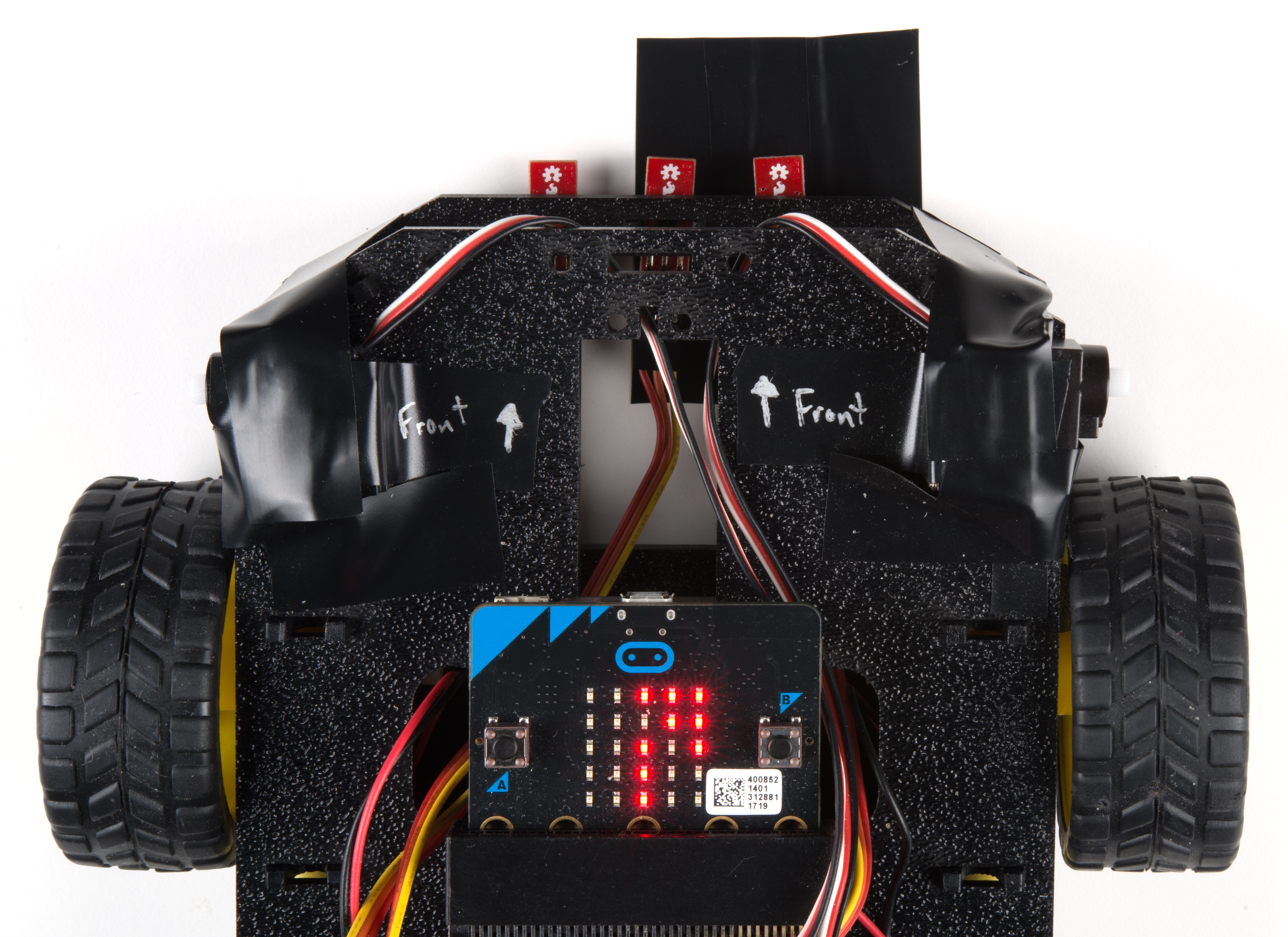
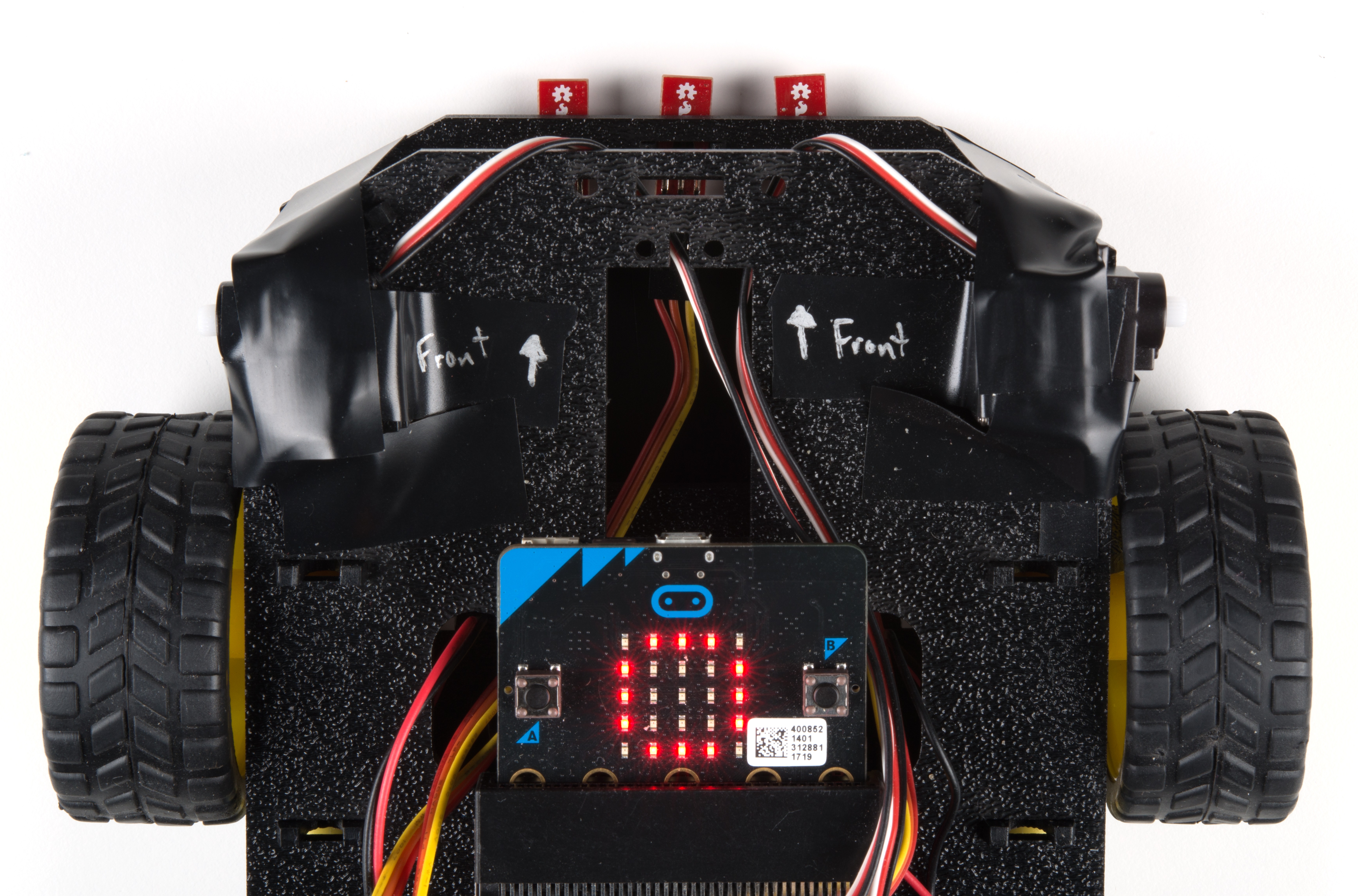
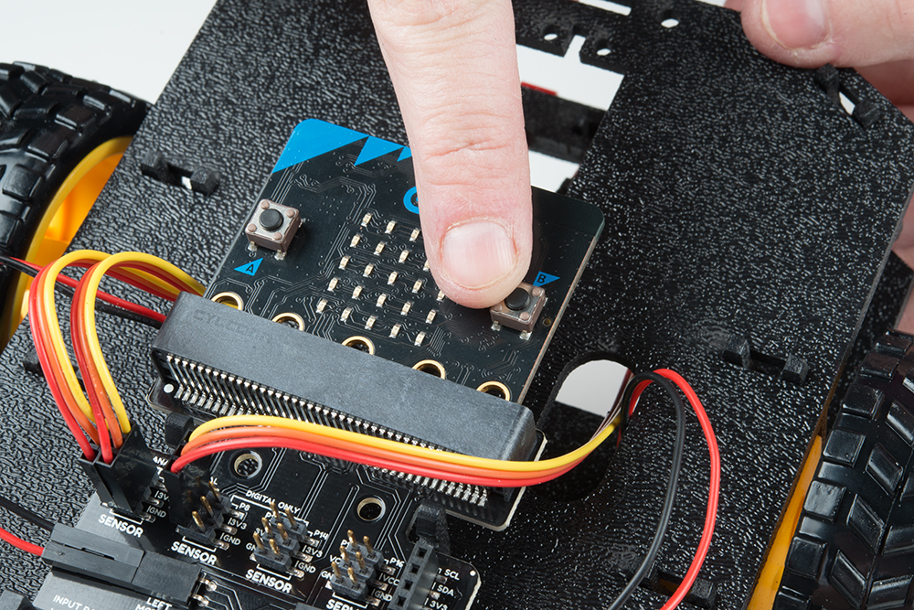
As in the first experiment, we use the On Button Press block to start the program. Since we are using button A again to recalibrate the line following sensors whenever we need, we'll be using button B to start the program. This is so you can get a good base reading to calibrate your sensors without having to wrestle with a robot that is trying to move around. To remind us to press button B, the on start block displays a short animation once to point at button B. If the motor switch is flipped to the RUN MOTORS side, pressing button B will cause the micro:bot to start following a line.
While
The While block is a logic block that is similar to the loop block, but a bit smarter. The While block accepts a TRUE/FALSE statement, if that statement is true the block will loop whatever code is placed inside of it. If that value is false, the While block is simply skipped over. We hardcode a true value into the While block so that it constantly loops when the B button is pressed. That way we have the benefits of both the event block and the loop block without needing complicated programming.
If Condition Statements
We'll use if/else statements once again to check the sensor readings and move the micro:bot:
- Case 1:
- If both are reading the same, move forward.
- Case 2:
- If the left sensor sees a dark black line but the other does not, move forward and a little to the left toward the dark black line closer to the left side of the micro:bot.
- Case 3:
- If the right sensor sees a dark black line but the other does not, move forward and a little to the right toward the dark black line closer to the right side of the micro:bot. There are slight differences in the motors and wheels so we tweak the left motor strength a bit so that the micro:bot actually turns toward the right (
50 + 5).
- If the right sensor sees a dark black line but the other does not, move forward and a little to the right toward the dark black line closer to the right side of the micro:bot. There are slight differences in the motors and wheels so we tweak the left motor strength a bit so that the micro:bot actually turns toward the right (
- Case 4:
- If we do not see a dark black line, stop.
What You Should See
Serial Output
You can pair, upload code to the micro:bit, and view the output on the MakeCode console without having to drag and drop the file to the micro:bit after updating the firmware. For more information about using the WebUSB feature on MakeCode, make sure to check out the instructions provided by micro:bit support.
Otherwise, you can use your favorite serial terminal or program to real time, serial data plotter to graph the output.
We'll use the MakeCode console to output the serial output again. If you have paired the micro:bit to your computer and used the one-click download feature for MakeCode, a "Show console Device" button should appear in MakeCode. Click on the button to view the serial output.
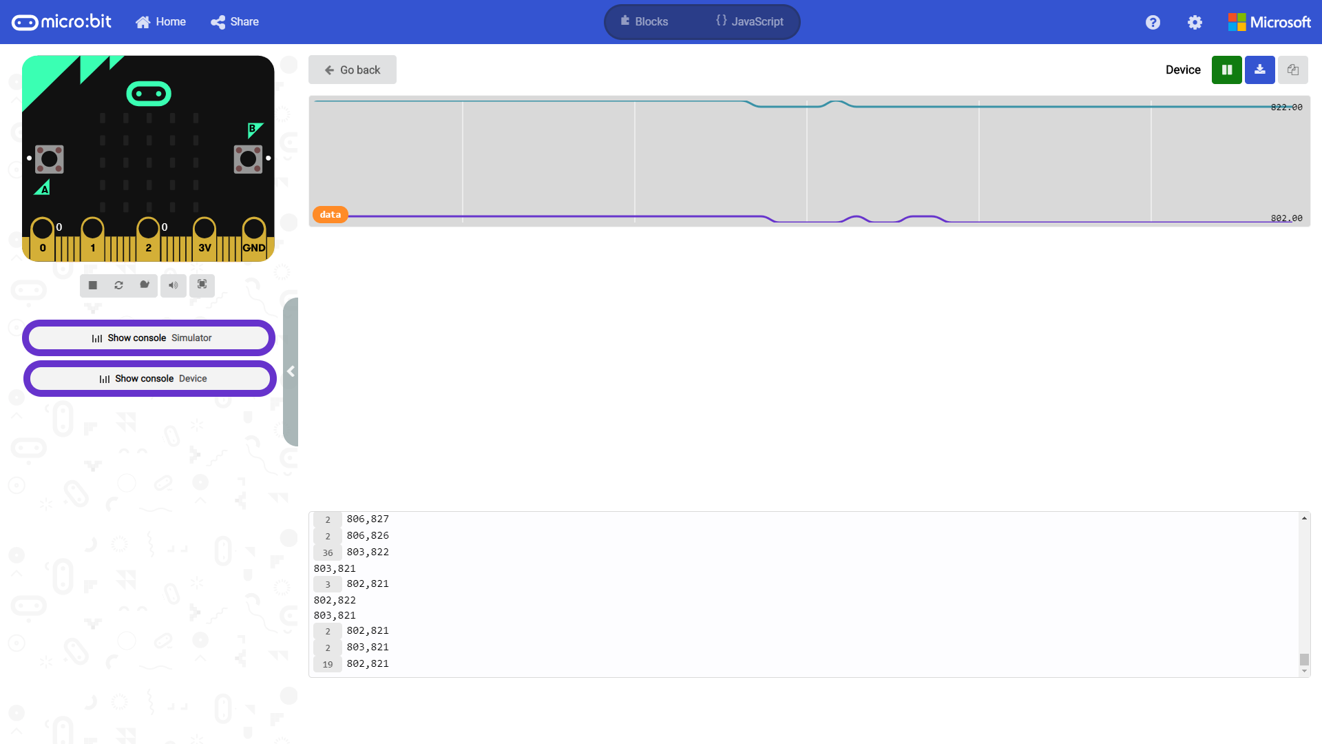
You will notice that the data will start jumping around as the line following sensors on P0 and P2 read the surface. Below is a snapshot of the line following sensors on a light surface. Notice that the output of both sensors were not the same. This is due to the slight differences in the line following sensors. You may see a different output with your sensors.
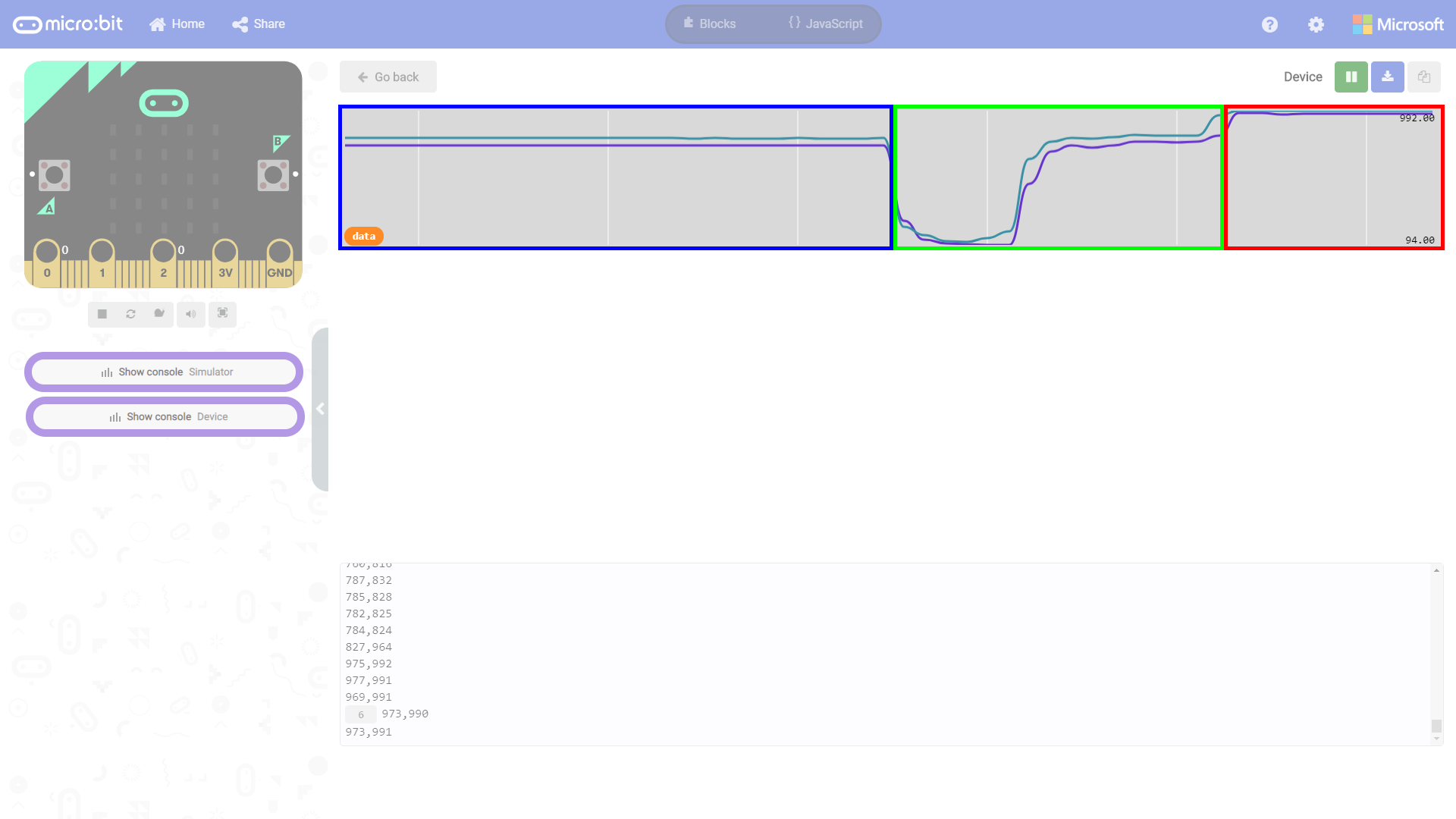
Moving the micro:bot over a piece of brown cardboard and black electrical tape, you will notice that the sensor readings move at the same time when the graph zooms out.
 |
 |
|
| White Table under P0 and P2 | Brown Cardboard under P0 and P2 | Black Electrical Tape under P0 and P2 |
For this reading, we moved the micro:bot further into the cardboard so that the distance between the line following sensors and cardboard box were the same.

Let's look at the same graph but highlighted for the different surfaces. Overall, the output is similar to what we saw in experiment 2 when the motors are turned off.
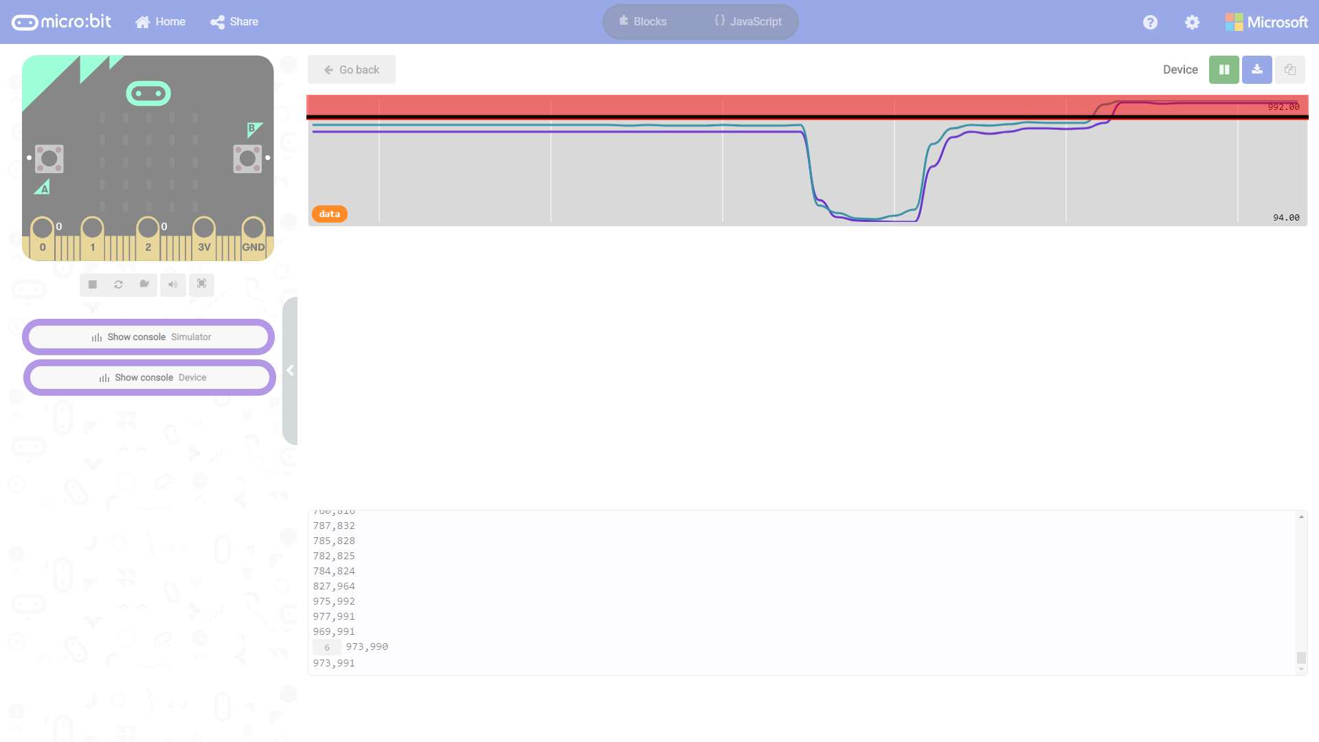
The image below highlights the area where it is above black_line_L - 100 and black_line_R - 100. Note that we need to do this for the left and right line following sensor due to the slight differences. As a result, anything above ~875 for the left line following sensor (as indicated by the red line) is probably a dark surface. Additionally, anything above ~892 for the right line following sensor (as indicated by the black line) is probably a dark surface.
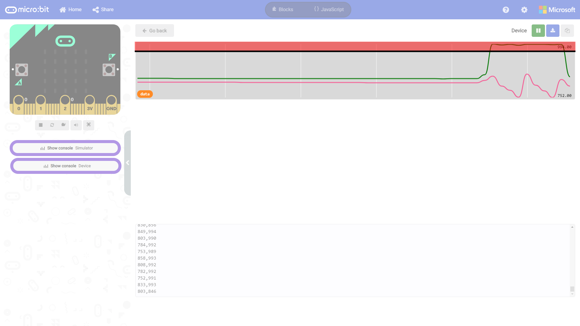
As we turn on the motors for the micro:bot and view the data, the output will become noisy instead of being a steady output. You'll also see the output become slightly bigger when ever the motors are turned on whenever it tries to follow a dark black line. The image below highlights the area when both sensors see a dark black line. When this happens, the micro:bot will drive forward.
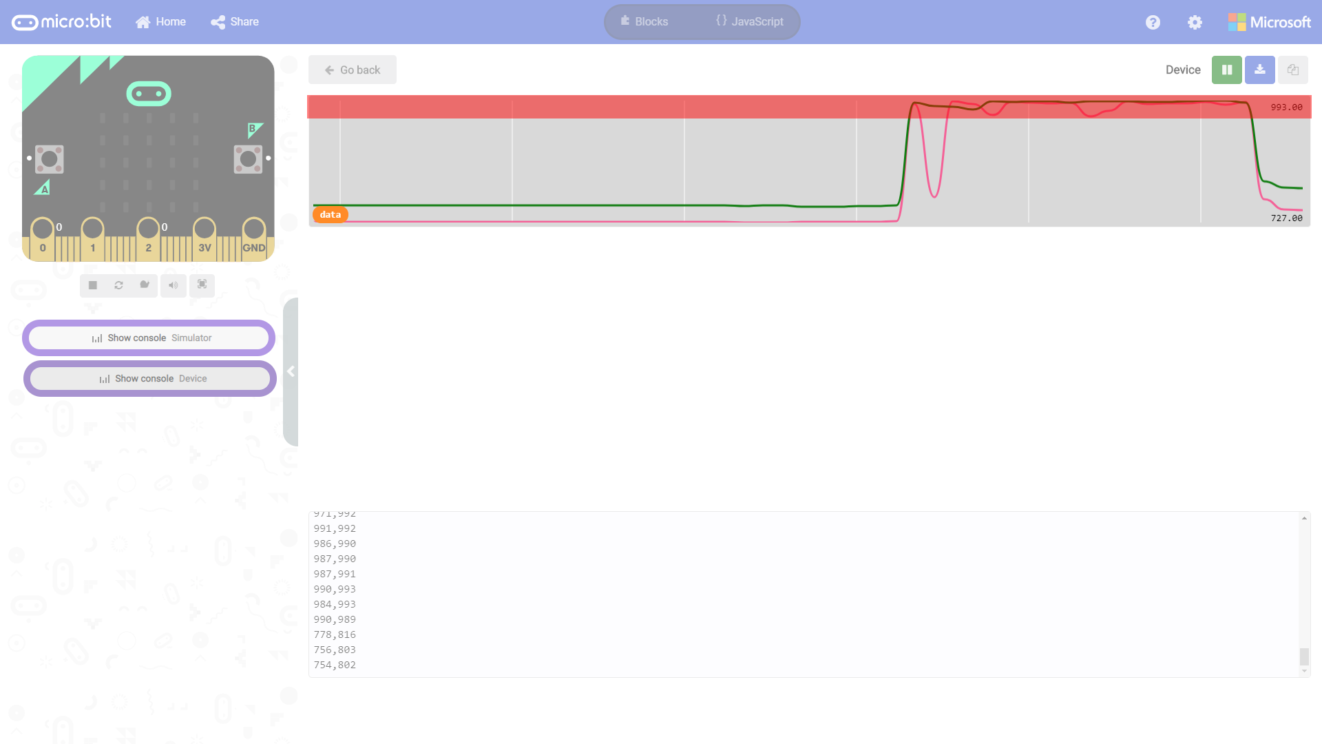
The image below shows when the left line following sensor (when it is above black_line_L - 100) sees a dark black line. The motors turn on and tries to move toward the line on the left. Note that the right line following sensor stays around the same value but becomes noisy.
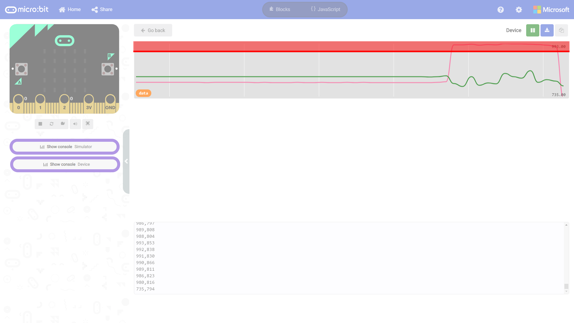
The image below shows when the right line following sensor (when it is above black_line_R - 100) sees a dark black line. The motors turn on and tries to move toward the line on the right. Note that the left line following sensor stays around the same value but becomes noisy.
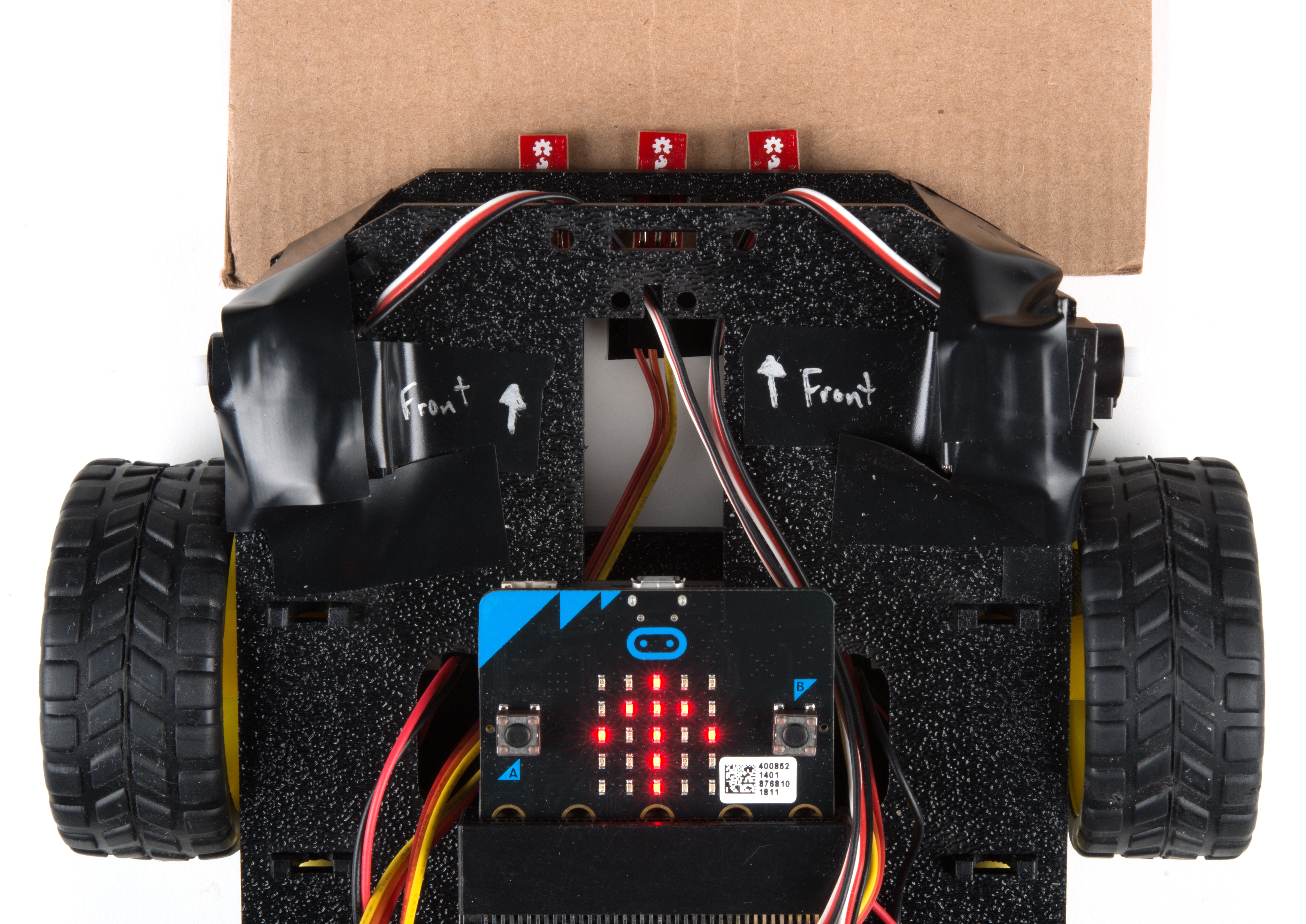
Straight Line Following micro:bot
Once you have loaded your script, place your robot on a dark black line on a light / white background. Make sure you have it centered with the line just underneath the center line sensor. Make sure the motor switch is changed from "STOP MOTORS" to "RUN MOTORS" and press the B button to start.
 |
 |
| Stop Motors | Run Motors |
Your robot should drive forward until one of the side line sensors detects the dark black line and then it will turn in that direction to correct itself. Depending on your line shape and thickness your robot may "waddle" more or less. If you have the motors running too fast, it will continue moving until it sees a light surface. Make sure to have the robot slowly move forward or it may fall of the edge of a table!
Experiment 3b -- Following a Course with Zigzags
Now that the micro:bot can follow a straight line, let's try to have the micro:bot follow simple polygon with zigzags.
Running Your Script
Be sure to add the moto:bit package as instructed in the Installing the moto:bit Package in MakeCode section of this tutorial.
Now, you can either download the following example script below and drag and drop it onto your micro:bit, or use it as an example and build it from scratch in MakeCode.
Code to Note
Let’s take a look at the code and what to expect.
Modified If Condition Statement
Most of the code used for experiment 3B is pretty much the same when following a black line. You should see the same condition statements for case 1 through case 3 when using P0 and P2 as the micro:bot attempts to follow a dark black line.
|
|
|
| Case 1 - Moving Forward | Case 2 - Moving Forward and Left | Case 3 - Moving Forward and Right |
However, case 4 will be adjusted to keep searching for a path. If we do not see a dark black line, we will take a step back and search three times to the left. The variable move_left will keep track of how many times we have looked to the left. Each time we search to the left, we will increase the power of the motor so that we do not get stuck in the same spot. After the 3rd time, we will try looking to the right before starting all over again.

We will only want to use the move_left variable in case 4. We'll reset the variable whenever we go into the other cases.
What You Should See
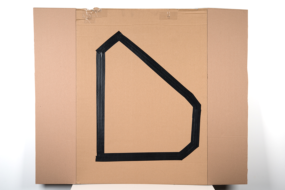
The serial output will be the same if you open the MakeCode console. If you need, you can open it back up to view the output. If you have not already, make a track on a flat surface with varying edges. Make sure that there is enough of material adjacent to the track. If the wheels or nub caster run off the track, it may have problems trying to get back on the surface. We used a cardboard surface with black electrical tape for this experiment. Additional cardboard was attached to prevent the micro:bot from getting stuck.
This example works well to follow small changes in the line for turns but will also adjust for sharp turns. You'll follow the same steps to get the robot to start following a line. The only difference is that the robot will follow a zigzagged course in this example. By default, the micro:bot will attempt to correct itself to eventually follow a track in a counter-clockwise motion. Keep in mind that there are limitations in following a dark black line when only using only two line following sensors. Additionally, the surface was not completely flat. As you can see from the GIF below that the floor was rocking as the micro:bot was following the line. Adding more line following sensors can help the micro:bot follow a line better and keep it from driving off the track.
- Try adding more code to utilize the center line following sensor.
- Instead of having the robot follow a counter-clockwise motion, try have the robot move in a clockwise motion.
- Adjust the code to follow a dark black line for a complex maze
- Adjust the motor speed and remove the LED array to see how fast your line following robot can move along the line without veering off the course.
- Use the built-in accelerometer to increase the motor speed whenever the micro:bot is on a slanted surface so that the robot can navigate rough terrain.
- Add an additional mode to invert the condition statements to follow a light white line against a dark surface instead of a dark black line against a light surface.
- Try adjusting the width of your track to see if the robot can follow a more narrow line.
Troubleshooting
Robot Drives In a Circle - Double check your wiring and your code, your robot is not seeing the line. Also, double check that there isn't something like dust blocking your sensor.
Robot Isn't Moving - Pesky motor switch! Make sure that is set to "run" and you have fresh batteries.
Robot Not Driving Forward - If your motors are hooked up correctly and we have inverted both motors in the code, try hitting the reset button on the micro:bit. This can happen after uploading when initially powering the micro:bit up.
Moving in Reverse?! - There are two options if you notice the micro:bot moving in the wrong direction. As explained above, you can flip the wiring of your motors or use the
set ____ motor invert to ____block in youron startblock to change what is forward vs. reverse.Robot Waddles a Lot! - Change the width of your line.
Robot Doesn't Detect Line - If changing the width of your line doesn't help, remember line sensor calibration settings can be very sensitive depending on your environment. Also, the code calibrates when the micro:bot starts up. Make sure to have the sensors over a black line.