micro:bot Kit Experiment Guide
 D___Run___,
  TheDarkSaint,
  bboyho, Ell C
 About the moto:bit Board
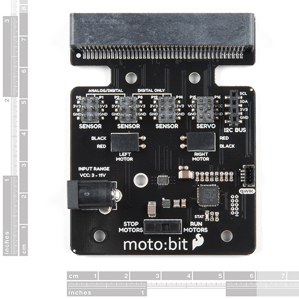
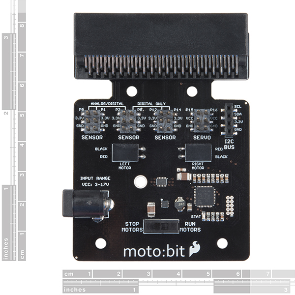
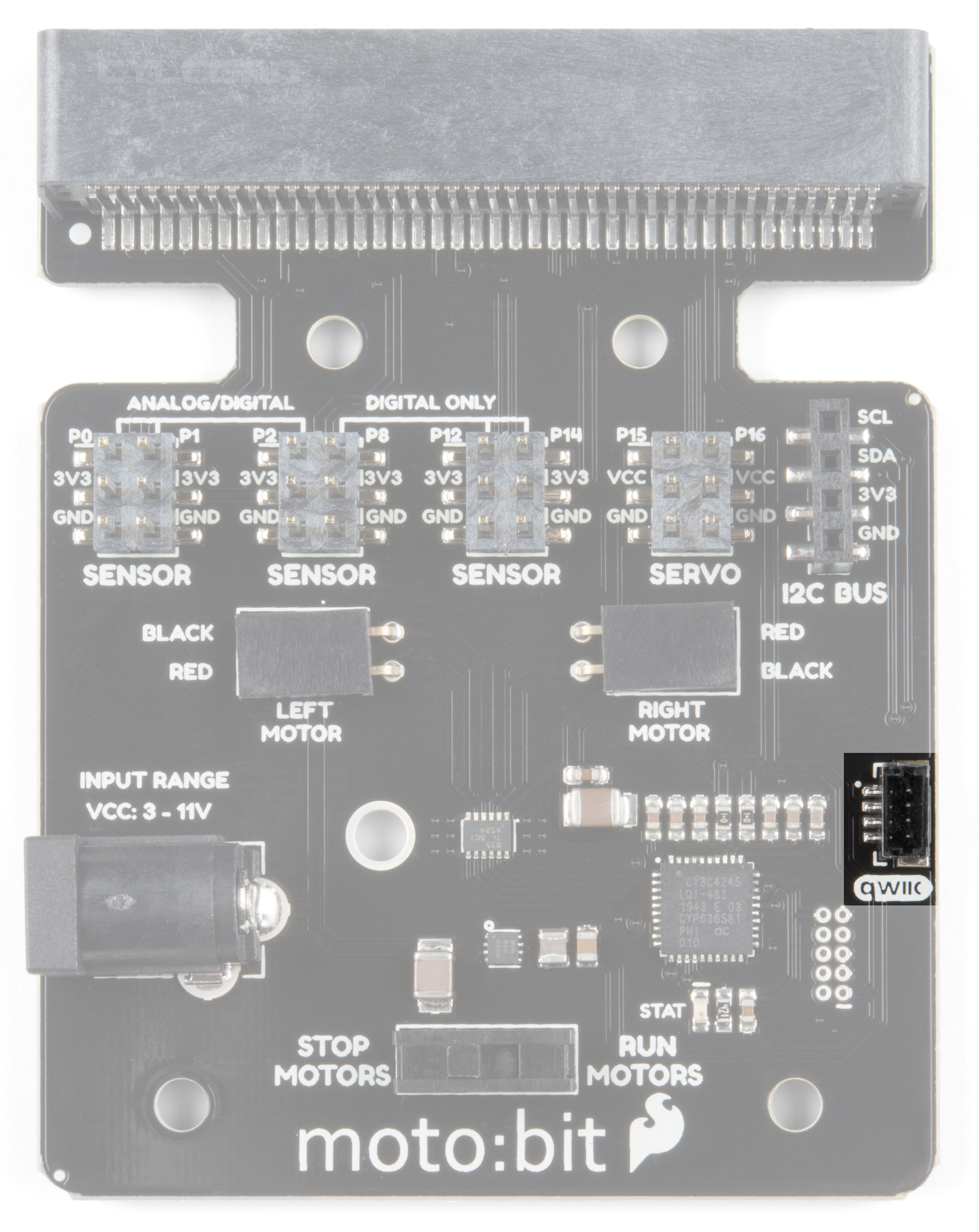
The moto:bit is a carrier board for the micro:bit. Similar to an Arudino shield, it is designed to add functionality to the micro:bit without the hassle of a number of other boards, soldering, and all of those jumper wires.
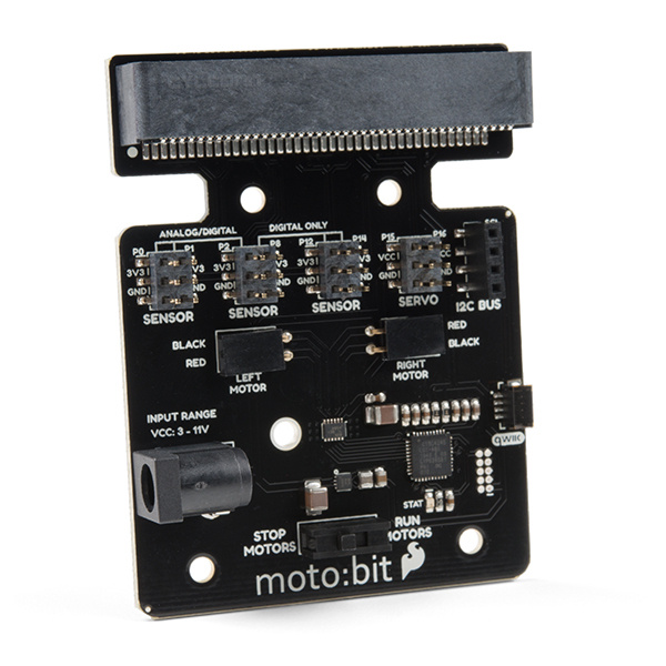
In this case, the moto:bit takes a micro:bit and turns it into a full blown robotics platform. Wondering what you can do with it? Well here are a few things...
- Control motors through an onboard H-Bridge
- Read digital sensors such as line and bump sensors
- Read analog sensors like light sensors, temperature sensors, etc
- Control servo motors
- I2C port for extending functionality
That is a lot of options in terms of bells and whistles! Let's take a closer look at the board and go over each section.
 |
 |
| Qwiic moto:bit [ DEV-15713 ] | moto:bit [ DEV-14213 ] |
Edge Connector
The moto:bit connects to the micro:bit via an edge pin connector. This makes it handy to swap out micro:bits for programming, and it creates reliable connections to all of the different pins on the micro:bit.
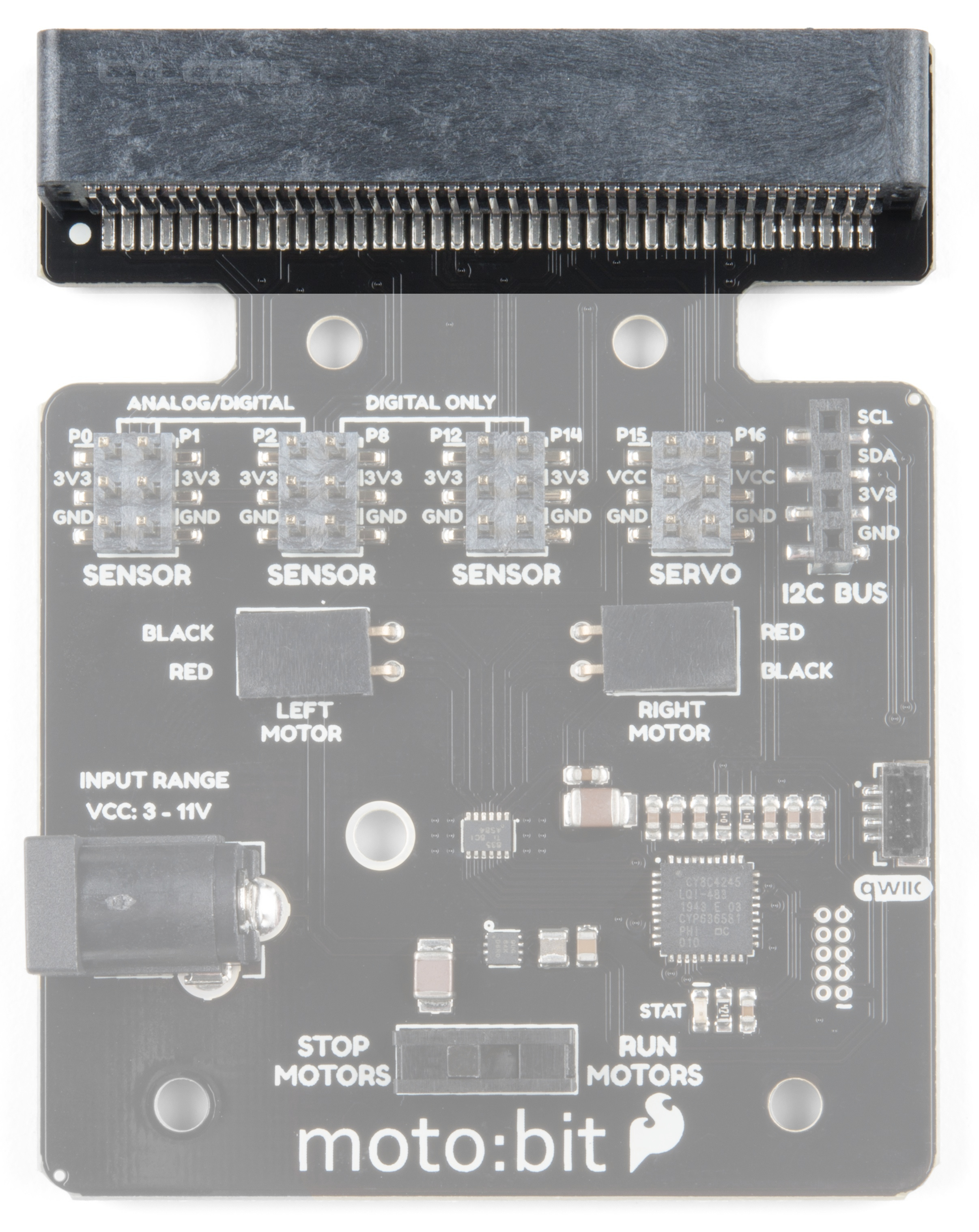
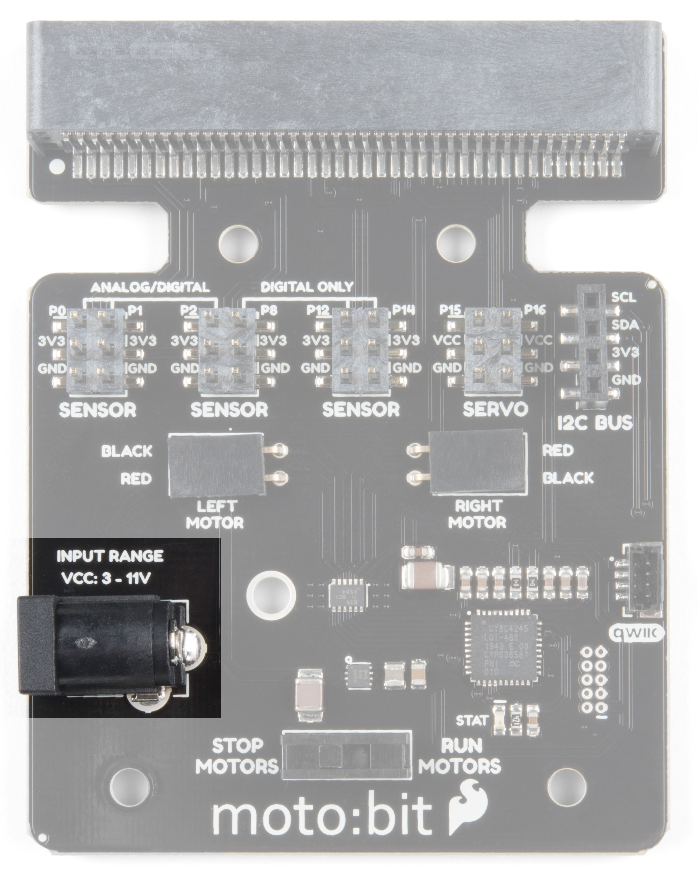
H-Bridge and Motor Pins
An H-Bridge is a chip that is the heart of a robot when it comes to driving motors and more specifically driving motors in both directions. Depending on the electrical state of specific pins on the H-Bridge, a motor drives forwards, backwards, and at different speeds. The good thing about this board is that if you are using Microsoft MakeCode, you actually don't really need to know a whole lot about the H-Bridge itself.
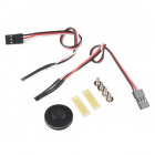
To connect the hobby motors that are included in the kit, you can insert them into the 2-pin female connectors just above the motor pins. The connectors are highlighted in the image below. Keep in mind that direction the hobby motors will move depends on the code to control the H-bridge motor driver, how the motors are attached to a chassis, and the way the motors are wired to the input pins.

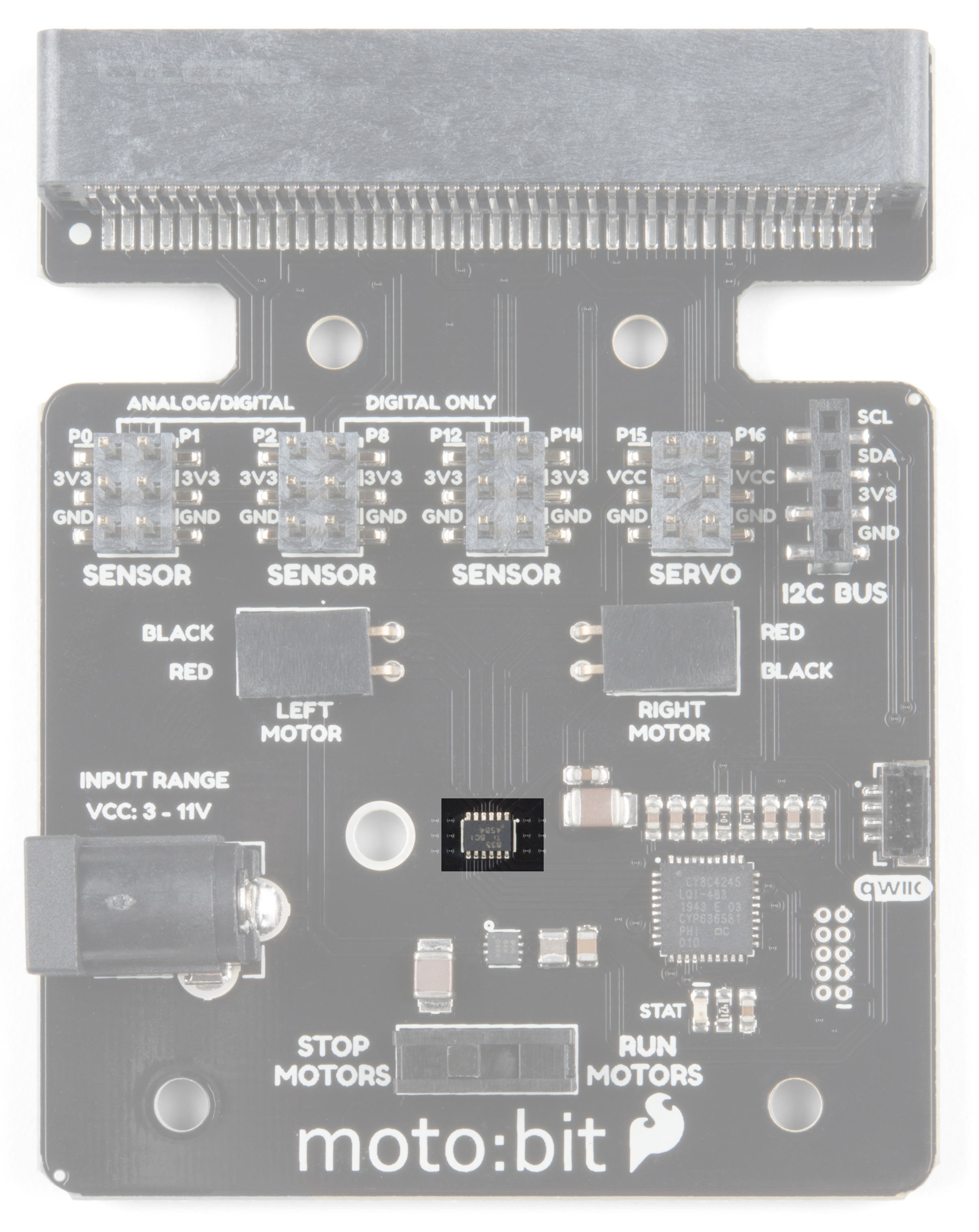
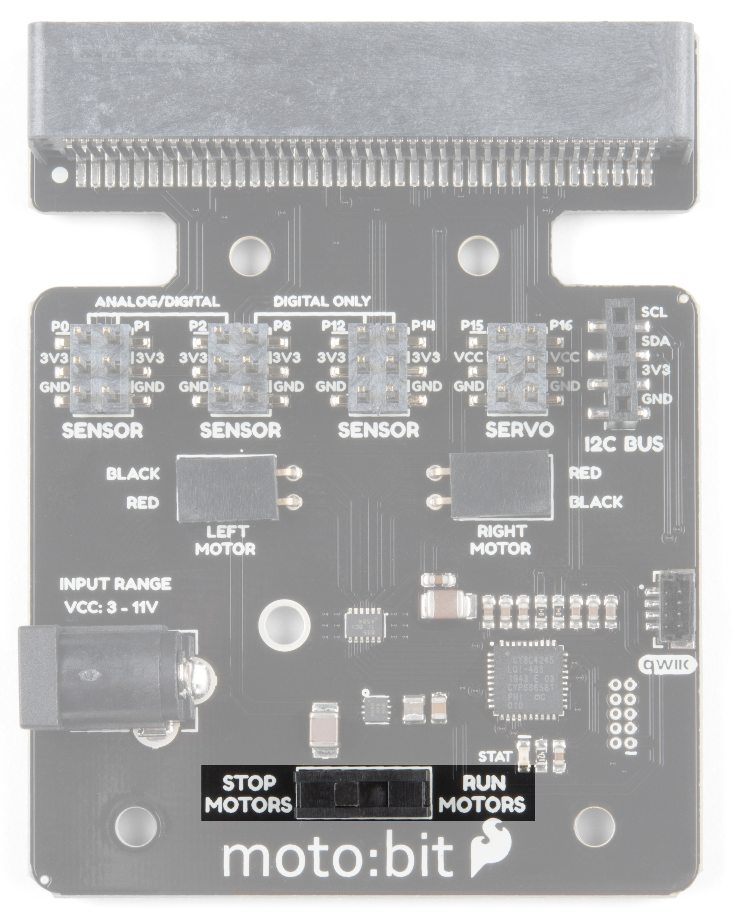
Motor Control Switch
The moto:bit has a switch that controls the power supply to the motors. That way you can have the robot powered while working on it or programming it and know that the robot is not going to start moving and drive off of the table. Believe us... that happens all the time!
Input and Output Pins
The male pins on the moto:bit are for hooking up various inputs and outputs on your robot without using a breadboard to build elaborate circuits.
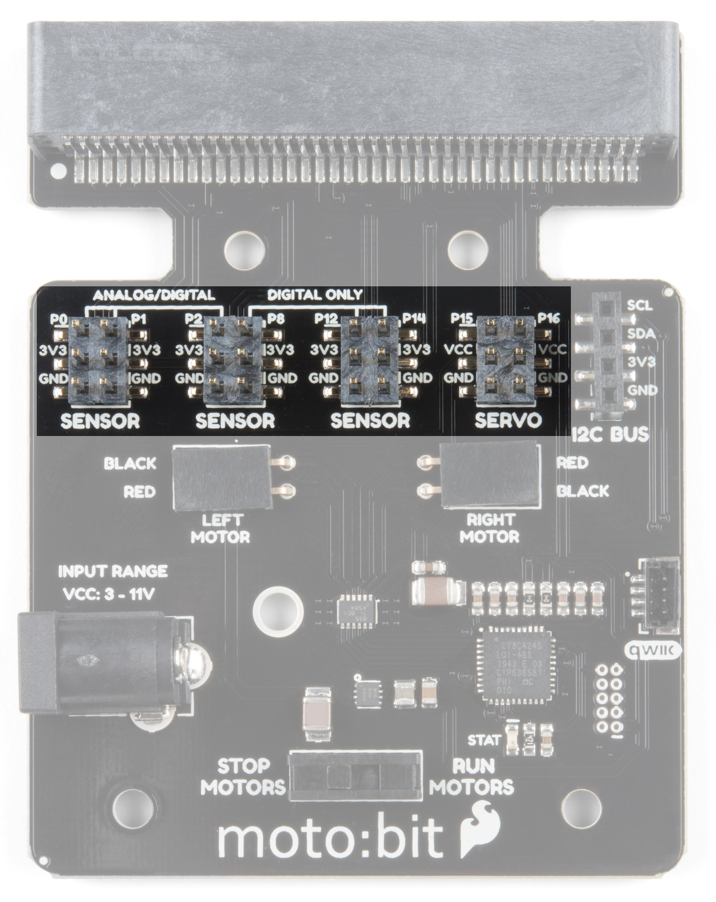
We have a number of sensors and actuators that are built in this pin formation and will work with this board.
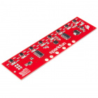
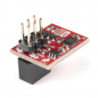
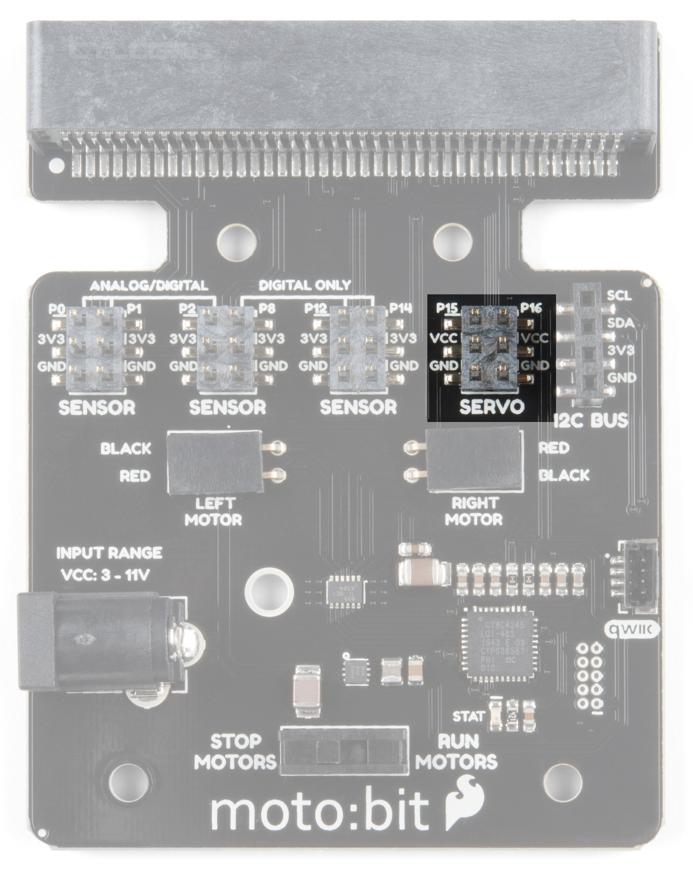
Servo Ports
No robot is complete without an arm, a swiveling "head," or some other type of movement other than wheels. Notice that a couple of the pin groups are designated as "Servo". You can connect servo motors directly to these pins and use them right out of the box with Microsoft MakeCode.
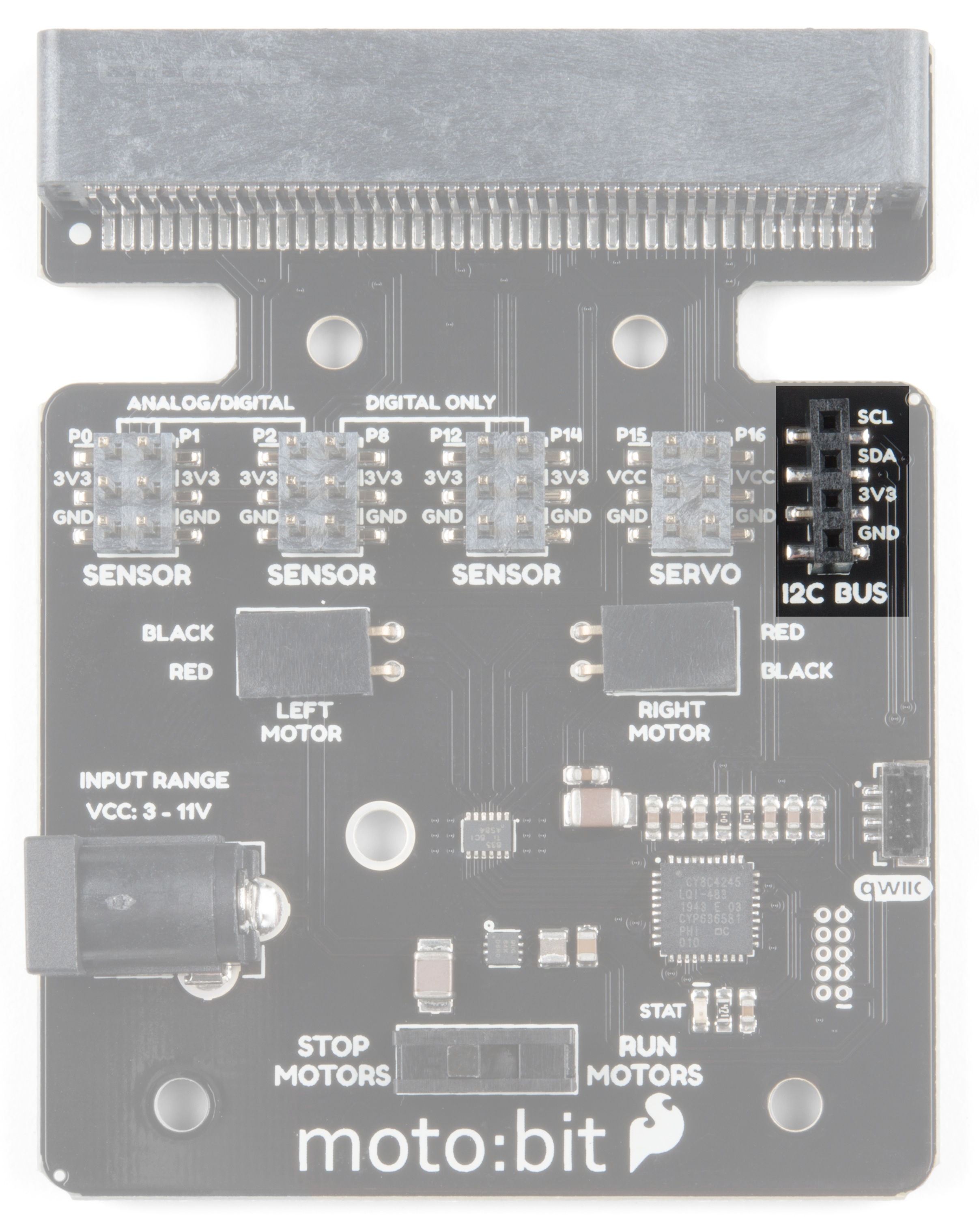
I2C Port
We broke out the I2C port of the micro:bit to an external port so that you can add any I2C capable sensor or actuator you can think of. It is standard pin arrangement to many of our I2C sensor breakout boards.
Qwiic Connector
With the updated moto:bit board, we've added a Qwiic connector so that our Qwiic line of products can be incorporated more easily.
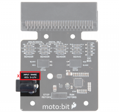
Power
A standard barrel jack connector is used for easily powering your robot. We find that a 4xAA battery pack works great, but it will accept between 3V-11V at the barrel jack. That's a whole lot of robo-power!