Lumenati Hookup Guide
 Pete-O
 Introduction
The Lumenati line of LED boards is designed to give your projects an edge in their lighting capacity. Based on the APA102C addressable LED, these LEDs employ a 2-wire communication protocol consisting of a clock line and a data line. While this requires one more wire than standard WS2812B addressable LEDs, the advantage is that the communication with the LEDs becomes somewhat timing independent, allowing you to run these directly off of a Raspberry Pi or other single-board computer that doesn't normally allow for a long, precicely-timed data stream without the use of additional hardware.
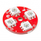
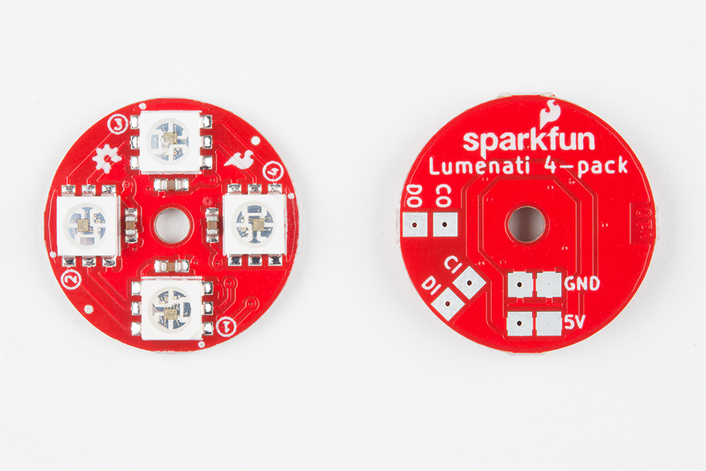
SparkFun Lumenati 4-pack
COM-14353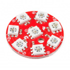
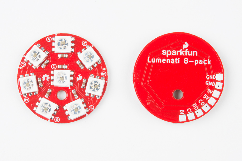
SparkFun Lumenati 8-pack
COM-14357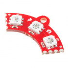
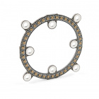
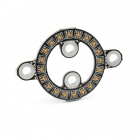
SparkFun Lumenati 90R
COM-14358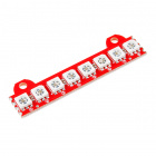
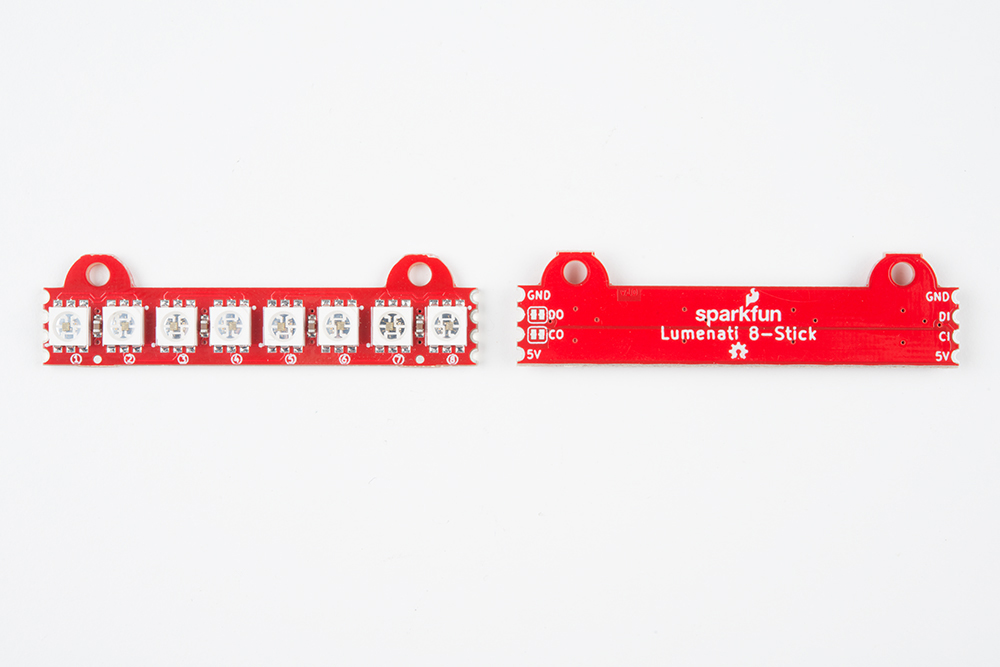
SparkFun Lumenati 8-stick
COM-14359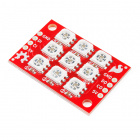
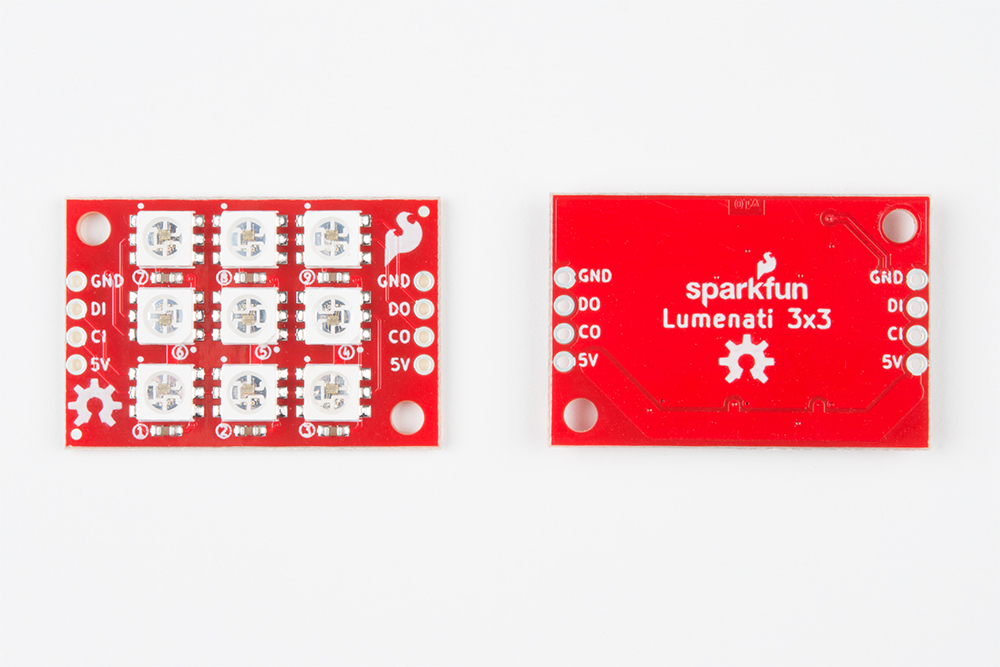
SparkFun Lumenati 3x3
COM-14360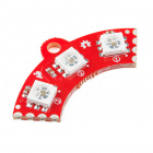
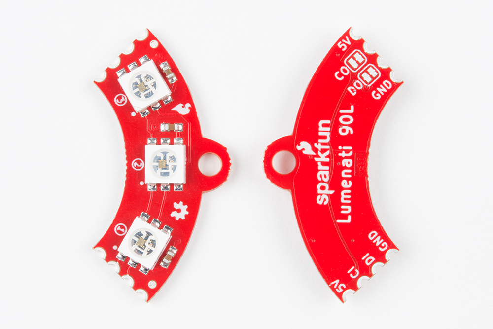
SparkFun Lumenati 90L
COM-14452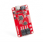
Required Materials
To get started, you're going to need a control system. Either a Raspberry Pi or Arduino will suffice for our examples, but really anything that has GPIO can be made to work.

Raspberry Pi 3
DEV-13825The APA102C addressable LEDs on the Lumenati boards operate natively with 5V logic, so it will save you trouble to choose a controller that can give you 0-5V, but it can be made to work with 3.3V logic with the use of a level translator.

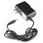
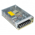
You will also need a power 5V power supply to run your controller and new lights. Each APA102C can draw as much as 60mA when red, green and blue are all full-on, so you'll want to have something a little beefy. We've chosen a wall adapter capable of 2.5A, which should be plenty for our demonstration. But if you've got a bigger project in mind, check out the Mean Well 5V/20A supply.
Tools
Lastly, you are going to need a few tools. A soldering iron, some solder, wire and a wire stripper should do. Maybe also some tweezers if you're not comfy with having your fingers close to the tip of a soldering iron.


Wire Strippers - 22-30AWG
TOL-14762Suggested Reading
We're tried to make this hookup guide as simple as possible, but you may be lacking some basic information that could help your understanding as we go forward. For more info, check out these tutorials...
How to Solder: Through-Hole Soldering
Installing an Arduino Library
How to Power a Project
Logic Levels
How to Solder: Castellated Mounting Holes
Raspberry Pi SPI and I2C Tutorial
Hardware Overview
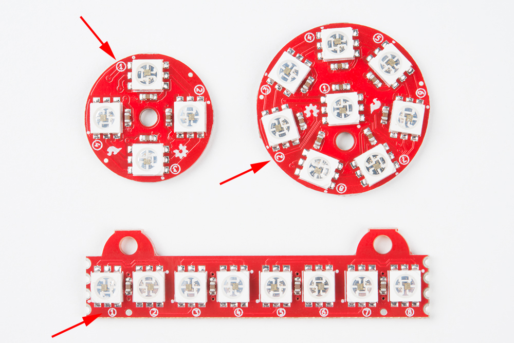
There are six different variations of Lumenati boards.
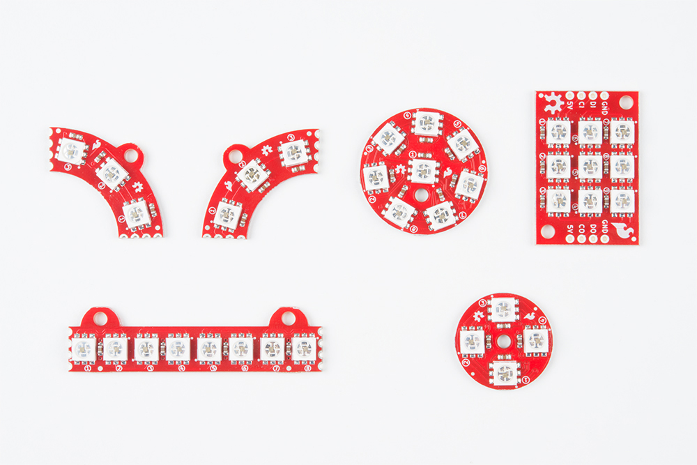
Each of the Lumenati boards are shown below:

Daisy-chaining Lumentai Boards
Any of the boards can be used stand-alone or daisy-chained. However, the 8-stick, 90L and 90R were designed with easy daisy-chaining specifically in mind.
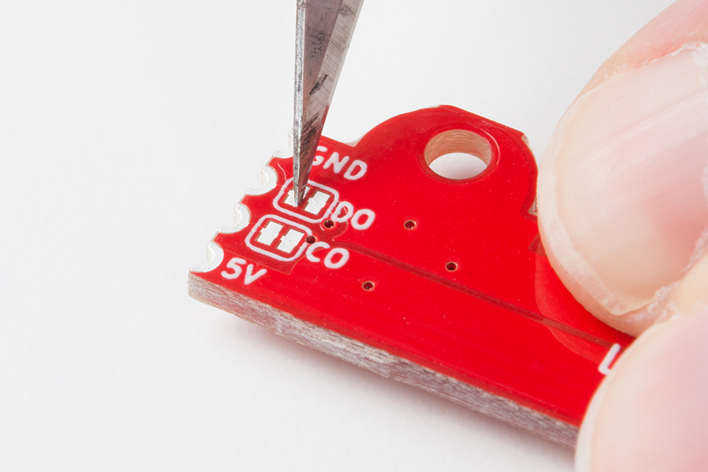
There are also solder jumpers on the CO and DO (clock out and data out) of these 3 boards. Those are there so that you can interrupt those signals in case you make a closed-loop design where you don't want the clock and data from your last LED to interfere with the clock and data to your first. +5V and ground traces are left to be contiguous in such cases to maximize current throughput. The solder jumpers on CO and DO come closed with a small trace bridging the solder pads. If you wish to open them, just take a small hobby knife (or similar implement of destruction) and carefully cut out that trace.
The APA102C addressable LEDs that are used on the Lumenati boards operate on +5V power input, as well as 0-5V logic levels for clock and data. The data interface is basically an SPI-like, with the exception that there is no data available coming back from the LEDs (no MISO line). Trace widths for +5V and ground have been maximized for better current through-put for long led chains.
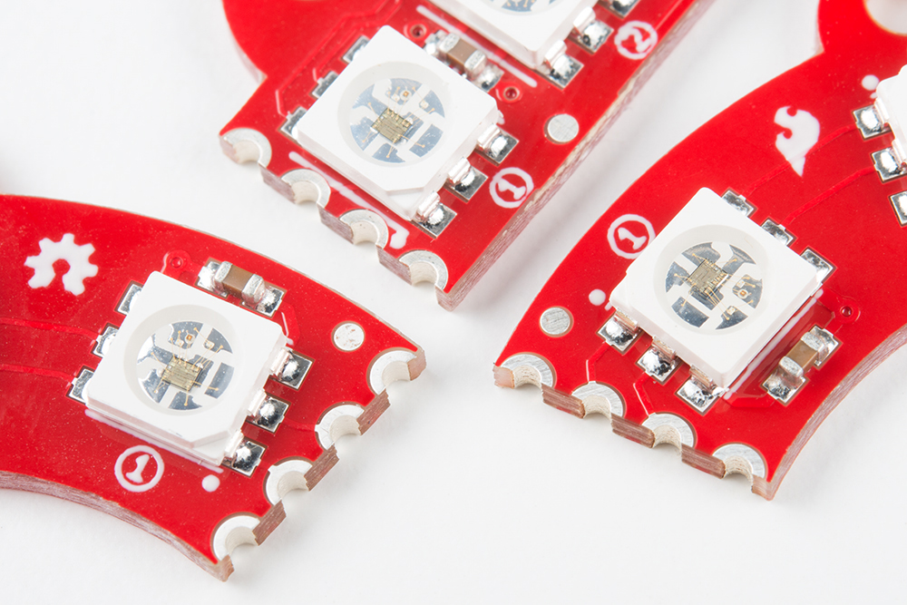
Additionally, LEDs on each board are labeled with numbers indicating their position in the sequence to help you design code more easily.
As mentioned earlier, each APA102C is capable of drawing close to 60mA when it's fully on. Care should be taken to keep that in mind when designing long LED chains. Figure out what your worst-case current draw could be, and plan accordingly!
Multiple Board Assembly
This section will cover the steps necessary to connect multiple Lumenati boards together.
Plan the Layout
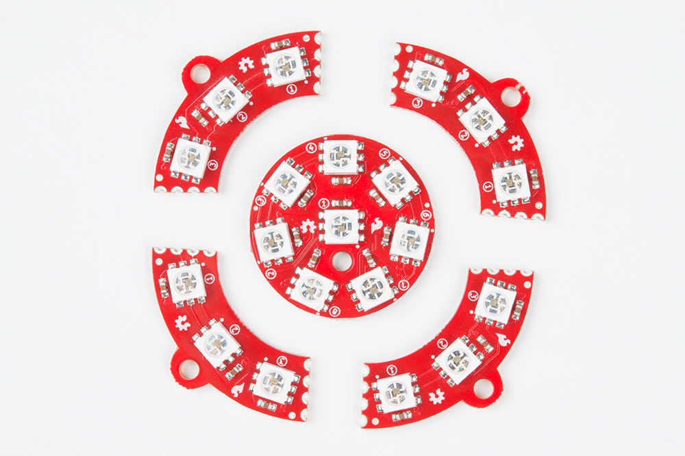
For our demonstration, we'll use four Lumenati 90L boards combined with a Lumenati 8-pack for a chain of 20 LEDs. Then we'll drive them with a Raspberry Pi 3 in our first example and a SAMD21 Breakout in the second.
To begin, gather the boards you want to use.
You may want to sand or file down some of the edges left from the panelization of the PCBs to aid in fitment at this point, but we'll leave that up to your judgement.
Soldering!
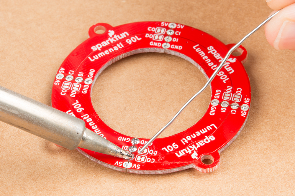
The four 90L boards will form a contiguous ring of LEDs. It would be difficult to get the clock and data signals off of the last 90L board (not impossible, but difficult), so we're going to put the 8-pack at the beginning of the chain. First, we'll solder up the four 90L's. To do this, you'll need a flat surface, preferably one that doesn't burn too much. A piece of cardboard works really great for this! Tin one of the corner connections (either power or ground) on one of the boards with some solder, like so:
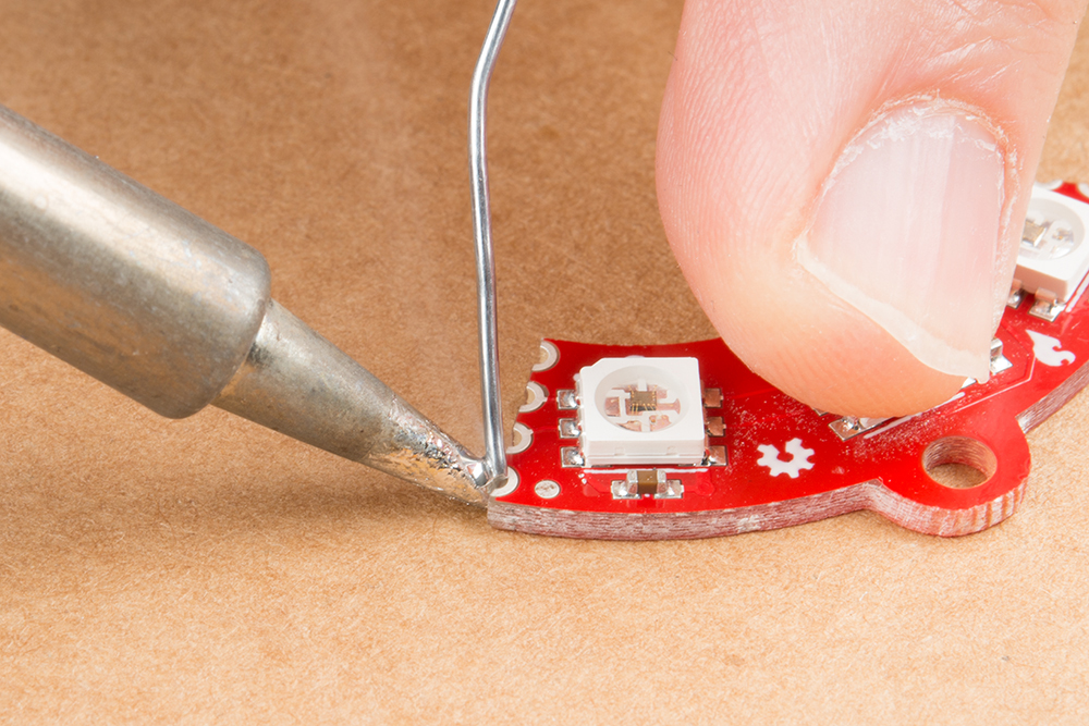
Then, butt the board you've just tinned up against the next board you want in the sequence, and reheat that solder you just placed so that it bridges between the two boards and forms enough of a mechanical connection to hold them together. Take care to make sure that both boards are as flat as you can get them to maximize both electrical and mechanical connections.
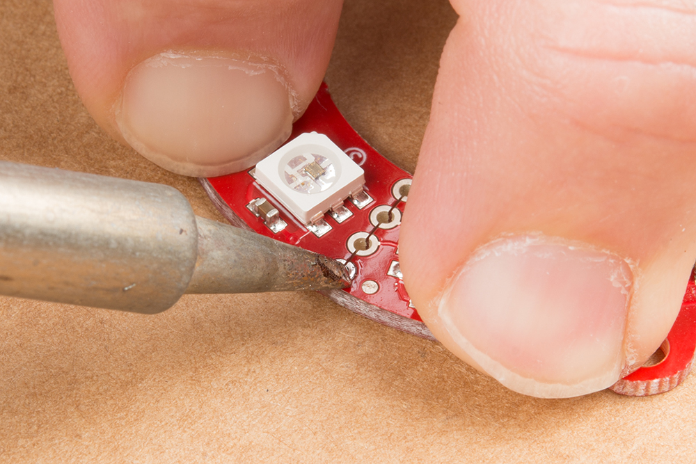
After you secure the first connection, solder the other three on both the top and bottom. This will make the boards as strong as possible. However, be aware that these can still break apart if put under too much stress. Mounting the boards to a solid backing is recommended, but they should still hold together fairly well if you're making something like a Christmas ornament or the like. For our demonstration, we're going to leave all the boards unmounted.
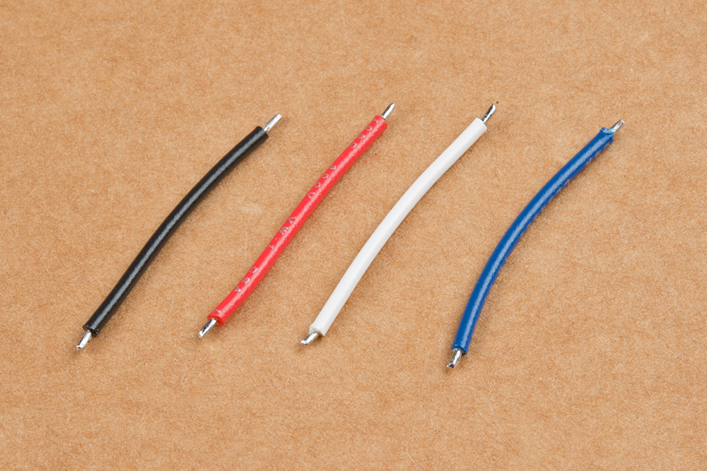
Next, solder the leads between the 8-pack and the four 90L boards. Cut four lengths of wire about 1 inch in length. We suggest color coding your wires for power (red), ground (black), clock and data (your call on those). Strip both ends of each wire about 1/16 inch to 1/8 inch, and tin them.
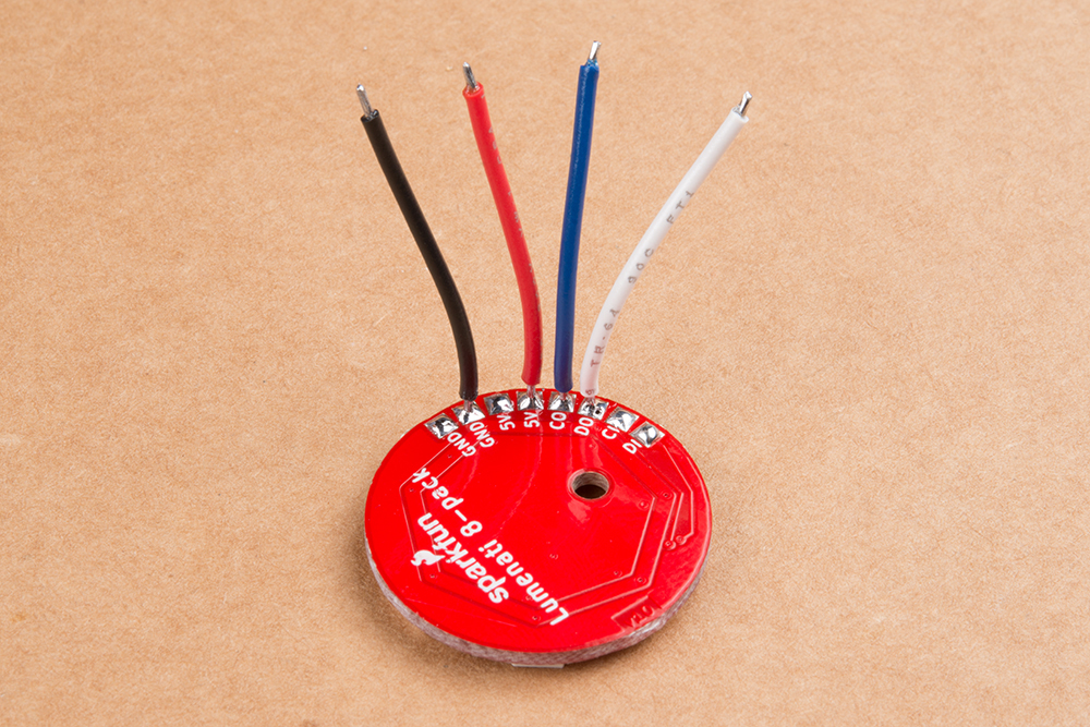
Tin all the solder pads of the 8-pack and solder your four leads to 5V (either of the two 5V pads), ground (either of the ground pads), CO and DO (Clock Out and Data Out). You can lay them out to the side if you wish, but we're going to sit them straight up so as to make positioning of the PCB easier.
Place the 8-pack board in the middle of the circle of 90L boards you've already made. Figure out how you'd like the board oriented, and pick one of the four interfaces between the four 90L boards to which you'll solder your four leads.
Once you've done that, solder down your leads - 5V to 5V, GND to GND, CO on the 8-pack to CI on the circle, and DO on the 8-pack to DI on the circle.

An alternate method of wiring to the 90L circle would be to solder up three of the four board interfaces leaving the fourth as open holes into which you can insert your 5V, GND, CO and DO lines. You will have to determine what your positioning is going to be before doing so.
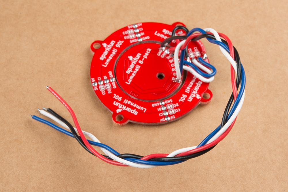
Now, you need to get power and signal to the thing you've constructed. To do so, just solder four more leads to the remaining 5V and GND pads on the 8-pack board, as well as CI and DI on the 8-pack. Braid the wires for some extra geek-cred. Now, it's ready to hook up to your control system!
Example Using a Raspberry Pi 3
For this example, we'll be using a Raspberry Pi 3, a PCA9306 Level Translator Breakout, a 5V power supply and the Lumenati boards that we put together in the last section. The hookup will look like this:
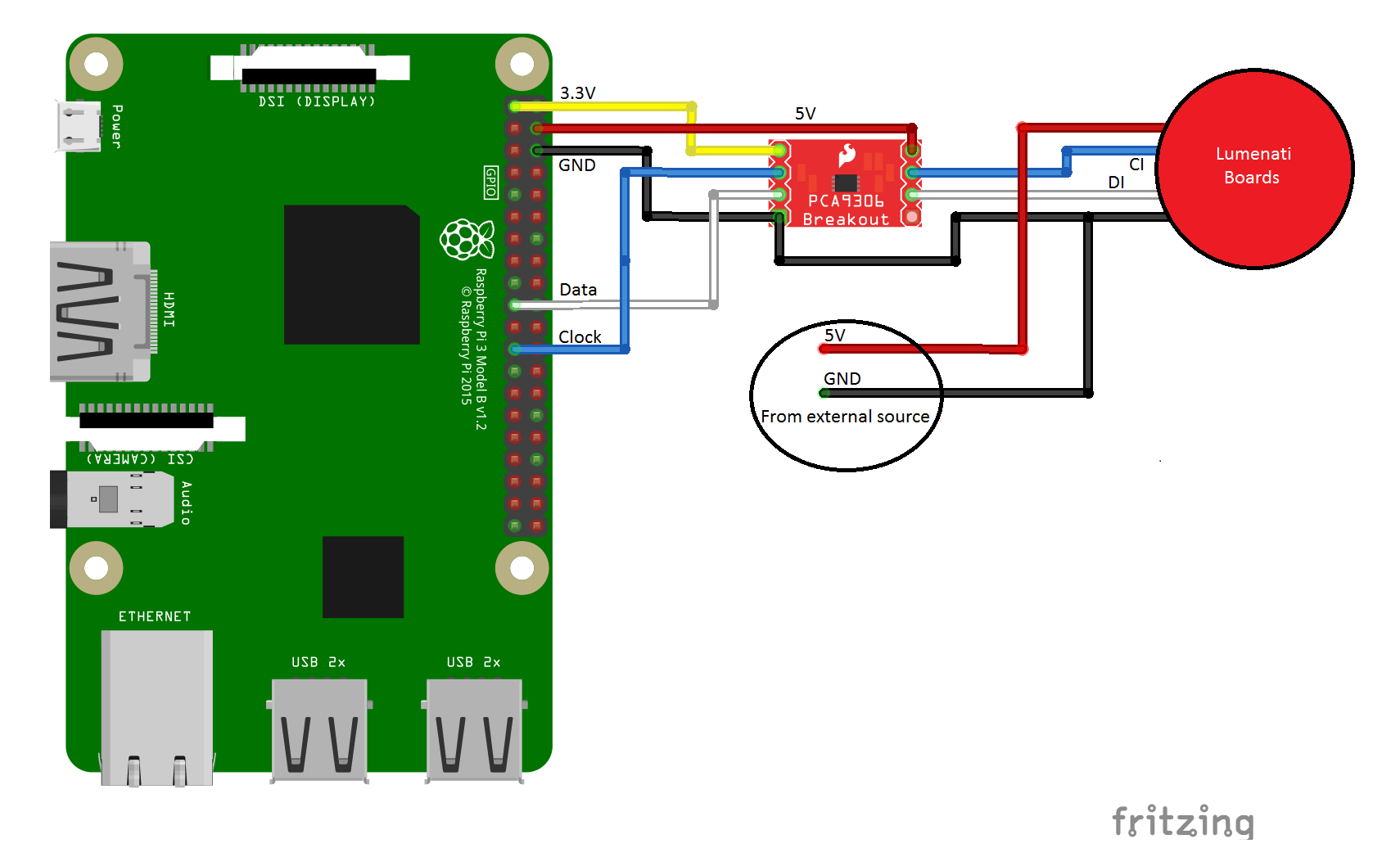
You'll notice from the diagram that the Lumenati boards are powered directly from an external 5V power supply and not from the header on the Raspberry Pi. While it is possible to drive the circuit as constructed with the supplied demo code from the Pi header, the 5V that's available there is fused. Since it is difficult to predict how much current the Pi itself is going to draw at any given moment, driving the LEDs through the Pi as well can become problematic with increased LED count and increased brightness, risking a brown-out condition with increased current consumption. Circumvent that condition entirely by tapping 5V and ground on the power supply before it reaches the Pi.
The connections of interest are in the following table.
| RasPi Pin # | Description | Goes to PCA9306 Pin |
|---|---|---|
| 1 | 3.3V (for low-side level shifting reference) | VREF1 |
| 4 | 5V (for high-side level shifting reference) | VREF2 |
| 6 | GND (ground for level shifting reference) | GND |
| 19 | Data | SCL1 |
| 23 | Clock | SDA1 |
Astute readers will notice that we've connected a clock signal to what looks like a data channel and a data signal to what looks like a clock channel on the PCA9306, if the labels are to be believed. But here's a little secret about those channels: they're virtually identical, electrically speaking. While the labels may be incongruent, it made the wiring just slightly more uniform.
The connections from the PCA9306 Breakout to the Lumenati boards are thus:
| PCA9306 Pin | Description | Lumenati Pin |
|---|---|---|
| SDA2 | Clock | CI |
| SCL2 | Data | DI |
| GND | GND (ground for level shifting reference) | GND |
We've put together some really simple python code for you to get started with. The first is a really simple library to set up an array with the LED parameters and write them to the Lumenati boards.
language:python
#Set up the SPI port on the Pi
import spidev
spi = spidev.SpiDev()
spi.open(0,0)

#Create LED array by sending this function num_LEDs
def set_LED_quantity(num_LEDs):
    global NUM_LEDs
    NUM_LEDs = num_LEDs
    global LED_array
    LED_array = [[0,0,0,0]] * NUM_LEDs

#Puts LED(num) parameters into LED_array
#Red, Green and Blue (r,g,b) values must be between
#0-255. Brightness must be between 0 and 31.
def set_LED(num, r, g, b, brightness):
    if (brightness > 31) | (brightness < 0):
        brightness = 15
    if (r > 255) | (r < 0):
        r = 100
    if (g > 255) | (g < 0):
        g = 100
    if (b > 255) | (b < 0):
        b = 100

    LED_array[num] = [r, g, b, brightness | 0xE0]

#These 4 bytes have to be written at the start and
#end of each data frame when writing to the LEDs
def _start_end_frame():
    for x in range (4):
            spi.xfer2([0x00])

#Write data to the LEDs
def WriteLEDs():
    _start_end_frame()
    for LED in LED_array:
        r, g, b, brightness = LED
        spi.xfer2([brightness])
        spi.xfer2([b])
        spi.xfer2([g])
        spi.xfer2([r])

    _start_end_frame()
The second demonstrates the use of those functions and makes some pretty lights.
language:python
#This is demonstration code for the Lumenati line of APA102c boards,
#specifically using (4) 90L boards surrounding one 8-pack board.

import time

from SFE_Lumenati import set_LED_quantity, WriteLEDs, set_LED

#Set up array, 20 LEDs
set_LED_quantity(20)

#Delay duration
wait = 0.15

#Global brightness
brightness = 15 #range is 0-31

try:
    while True:

        for y in range (5):

            #center, white
            set_LED(0,25,25,25,brightness)

            #inner ring, red
            for x in range (7):
                set_LED(x+1,25,0,0,brightness)

            #outer ring, white
            for x in range (12):
                set_LED(x+8,25,25,25,brightness)

            #Write to the LEDs and wait
            WriteLEDs()
            time.sleep(wait)

            #center, red
            set_LED(0,25,0,0,brightness)

            #inner ring, white
            for x in range (7):
                set_LED(x+1,25,25,25,brightness)

            #outer ring, red
            for x in range (12):
                set_LED(x+8,25,0,0,brightness)

            #Write to the LEDs and wait
            WriteLEDs()
            time.sleep(wait)

        for y in range (5):

            #center, yellow
            set_LED(0,25,25,0,brightness)

            #inner ring, blue
            for x in range (7):
                set_LED(x+1,0,0,25,brightness)

            #outer ring, yellow
            for x in range (12):
                set_LED(x+8,25,25,0,brightness)

            #Write to the LEDs and wait
            WriteLEDs()
            time.sleep(wait)

            #center, blue
            set_LED(0,0,0,25,brightness)

            #inner ring, yellow
            for x in range (7):
                set_LED(x+1,25,25,0,brightness)

            #outer ring, blue
            for x in range (12):
                set_LED(x+8,0,0,25,brightness)

            #Write to the LEDs and wait
            WriteLEDs()
            time.sleep(wait)

except KeyboardInterrupt:
    pass
Click here to get the code. Just drop the two files from SparkFun_Lumenati_Code/Firmware/RasPi into the same folder, and run Lumenati_Demo.py. If the stars align (and you've done everything right), the result should look as below.
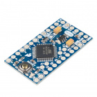
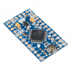
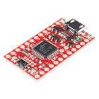
Example Using a SAMD21 Mini Breakout
Our second example uses a SparkFun SAMD21 Breakout board, which is Arduino-based, a PCA9306 Level Translator Breakout, a 5V power supply and the Lumenati boards that we put together in the assembly section. The hookup will look like this:
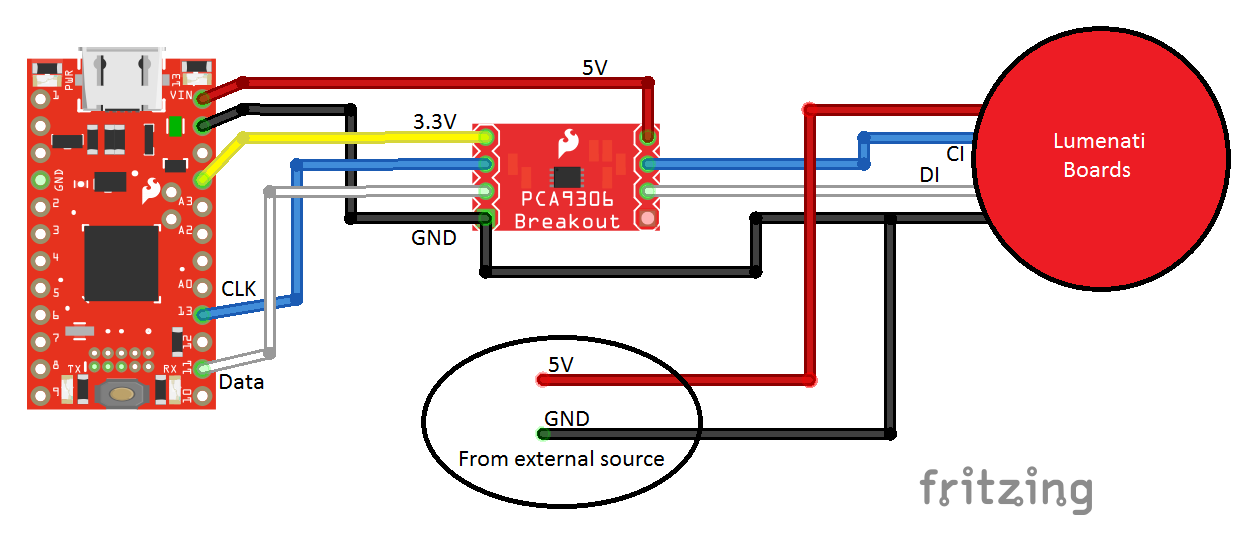
The circuit is almost identical to the Raspberry Pi example, except that there's a SAMD21 Breakout where the Pi was. The specific connections to the SAMD21 are as follows:
| SAMD21 Pin label | Description | Goes to PCA9306 Pin |
|---|---|---|
| VIN | 3.3V (for low-side level shifting reference) | VREF1 |
| VCC | 5V (for high-side level shifting reference) | VREF2 |
| GND | GND (ground for level shifting reference) | GND |
| 11 | Data | SCL1 |
| 13 | Clock | SDA1 |
Again, the channels on the PCA9306 with regard to SCL and SDA are not electrically critical; either channel can do either function, clock or data. This swap just made our wiring slightly cleaner. Everything else in this circuit is identical to the RasPi example.
For the code, this time we're going to use the FastLED library. If you haven't already done so, now is a good time to install that library. Haven't installed a library in Arduino before? Click here for more info.
Our example code is as follows:
language:c
#include "FastLED.h"

//Number of LEDs
#define NUM_LEDS 20

//Define our clock and data lines
#define DATA_PIN 11
#define CLOCK_PIN 13

//Create the LED array
CRGB leds[NUM_LEDS];

void setup() {

      //Tell FastLED what we're using. Note "BGR" where you might normally find "RGB".
      //This is just to rearrange the order to make all the colors work right.
      FastLED.addLeds<APA102, DATA_PIN, CLOCK_PIN, BGR>(leds, NUM_LEDS);

      //Set global brightness
      FastLED.setBrightness(50);
}

void loop() {

  uint8_t x;
  uint16_t wait = 100;

  //Check out all these wacky colors! Have a look at teh FastLED documentation for more.
  //Turn on each LED in succession
  leds[0] = CRGB::Blue;
  FastLED.show();
  delay(wait);

  leds[1] = CRGB::Green;
  FastLED.show();
  delay(wait);

  leds[2] = CRGB::Purple;
  FastLED.show();
  delay(wait);

  leds[3] = CRGB::AliceBlue;
  FastLED.show();
  delay(wait);

  leds[4] = CRGB::DarkGoldenrod;
  FastLED.show();
  delay(wait);

  leds[5] = CRGB::DarkGreen;
  FastLED.show();
  delay(wait);

  leds[6] = CRGB::DeepSkyBlue;
  FastLED.show();
  delay(wait);

  leds[7] = CRGB::GreenYellow;
  FastLED.show();
  delay(wait);

  leds[8] = CRGB::LawnGreen;
  FastLED.show();
  delay(wait);

  leds[9] = CRGB::Maroon;
  FastLED.show();
  delay(wait);

  leds[10] = CRGB::FairyLight;
  FastLED.show();
  delay(wait);

  leds[11] = CRGB::Tomato;
  FastLED.show();
  delay(wait);

  leds[12] = CRGB::Turquoise;
  FastLED.show();
  delay(wait);

  leds[13] = CRGB::SpringGreen;
  FastLED.show();
  delay(wait);

  leds[14] = CRGB::Salmon;
  FastLED.show();
  delay(wait);

  leds[15] = CRGB::Sienna;
  FastLED.show();
  delay(wait);

  leds[16] = CRGB::SeaGreen;
  FastLED.show();
  delay(wait);

  leds[17] = CRGB::Teal;
  FastLED.show();
  delay(wait);

  leds[18] = CRGB::OrangeRed;
  FastLED.show();
  delay(wait);

  leds[19] = CRGB::RosyBrown;
  FastLED.show();
  delay(wait);

  //Shut them off
  for (x = 0; x < NUM_LEDS; x++)
  {
    leds[x] = CRGB::Black;
  }

  FastLED.show();
  delay(wait);

}
This example will look completely different from the RasPi example, partly because we wanted to show off some of the colors available by some crazy names in the library. The FastLED library offers a LOT of versatility, probably far more than you're ever going to need. Check their documentation for a full listing of functions.
If you've already done the RasPi example, you've already got the Arduino code in your possession, as well. It can be found in the folder SparkFun_Lumenati_Code\Firmware\SAMD21. If you haven't got it yet, click here to get it. Load Lumenati_demo.ino onto your SAMD21, and watch the show!
If you've done everything right, your LEDs should be doing this:

Resources and Going Further
Here are links to more resources for the Lumenati boards.
SparkFun Lumenati 4-pack (Circular Disc)
- 4-pack (Circular Disc) Schematic (PDF)
- 4-pack (Circular Disc) KiCad Files (ZIP)
- 4-pack (Circular Disc) GitHub Repo
SparkFun Lumenati 8-pack (Circular Disc)
- 8-pack (Circular Disc) Schematic (PDF)
- 8-pack (Circular Disc) KiCad Files (ZIP)
- 8-pack (Circular Disc) GitHub Repo
SparkFun Lumenati 8-stick
SparkFun Lumenati 90R
SparkFun Lumenati 90L
SparkFun Lumenati 3x3
- APA102C Individual LEDs (pack of 10)
- APA102C Datasheet
- SparkFun Product Showcase: Lumenati
- SparkFun Project Showcase: Lumenati Skull
- How to Solder - Castellated Mounting Holes
- PCA9306 Level Translator Hookup Guide
- SAMD21 Hookup Guide
- SparkFun Lumenati Example Code GitHub Repository
- FastLED Arduino Library GitHub Repo
Need some inspiration for your next LED project? Check out these other great SparkFun tutorials.
Das Blinken Top Hat
Interactive LED Music Visualizer
LED Cloud-Connected Cloud
LED Crystal Goddess Crown
LuMini Ring Hookup Guide
LuMini 8x8 Matrix Hookup Guide
LumiDrive Hookup Guide
Or check out some of these blog posts for ideas: