LuMini Ring Hookup Guide
 Englandsaurus
 Introduction
The LuMini rings (3 inch, 2 inch, 1 inch) are a great way to add a ring of light to just about anything.
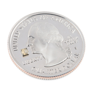
The LuMini line uses the same LED used on our Lumenati boards, the APA102, just in a smaller, 2.0x2.0 mm package. This allows for incredibly tight pixel densities, and thus, a more continuous ring of color. While the LuMini Rings come in different sizes, they all operate in a similar fashion.
 |
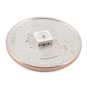 |
| Size of a APA102, 2020 Package | Size of a APA102, 5050 Package |
In this tutorial, we'll go over how to connect the LuMini rings up to more LuMini rings as well as other APA102 based products. We'll check out how to map out a ring of lights in software so we can get a little more creative with circular animations. We'll go over some things to consider as you string more and more lights together, and we'll also go over some neat lighting patterns to get you away from that standard rainbow pattern (if you have 16 million colors why would you use 255).
Required Materials
To follow along with this tutorial, you will need the following materials. You may not need everything though depending on what you have. Add it to your cart, read through the guide, and adjust the cart as necessary.
Choosing a Microcontroller
You'll need a microcontroller to control everything, however, there's a few things to consider when picking one out for the purpose of controlling a whole ton of LED's. The first thing is that, although they don't have to operate at a specific timing, APA102 LED's can transmit data really, really fast for LED's, like 20 MHz fast. So you should use a microcontroller fast enough to take advantage of this fact. Another thing to consider when you start getting into higher LED counts is the amount of RAM taken up by the LED frame. Each LED takes up 3 bytes of space in RAM, which doesn't sound like a lot, but if you're controlling 5000 LED's, well, you might need something with a bit more RAM than your traditional RedBoard. The below chart outlines the amount of LED's where you may start running into memory issues. Keep in mind that these are very generous estimates and will decrease depending on what other global variables are declared.
| Microcontroller | Max LED's | Clock Speed |
|---|---|---|
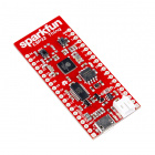
| SparkFun RedBoard | 600 | 16 MHz |
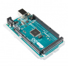
| Arduino Mega 2560 | 2600 | 16 MHz |
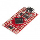
| Pro Micro | 700 | 16 MHz |
| SparkFun ESP8266 Thing | 27,000 | 160 MHz |
| SparkFun ESP32 Thing | 97,000 | 160 MHz or 240 MHz |
| Teensy 3.6 | 87,000 | 180 MHz (240 MHz Overclock) |
It's pretty easy to choose the ESP or Teensy when it comes to stuff like this, as you've got a ton of overhead in clock cycles to run wacky calculations for animations. However, if your project isn't all about lights, and you're just tossing a LuMini Ring on a project as an indicator, less powerful microcontrollers will suffice. Here are a few microcontrollers listed from the catalog. Depending on the development board, you may need to solder headers based on your personal preference.

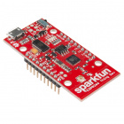
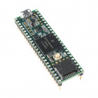
Teensy 3.6 (Headers)
DEV-14058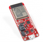
SparkFun Thing Plus - ESP32 WROOM
WRL-14689Selecting a Power Supply
In most cases, your LED installation is gonna pull more than your board can handle (Depending on brightness and animation, anywhere from 100-250 LED's can be too much for your board's voltage regulator to handle) so you should snag a sweet 5V power supply that's got enough wattage in the cottage for all of your LED's. Here are a few 5V power supplies listed in our catalog. Just make sure to get the appropriate cable and adapter when connecting to your power hungry LEDs.
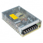
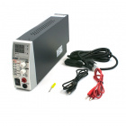
You can either estimate the necessary size of your power supply by taking the amount of LED's and multiplying by 60 mA (0.06 A) which is the amount of current it takes to run an LED at full white. This calculation will give you the maximum amount of power your LED's could draw, but most of the time, this is a gross overestimate of the amount of power you'll actually end up consuming. Instead of calculating, I usually like to test my completed installation on a benchtop power supply using the brightest animation it'll be running, and then add 20 or 30 percent to give myself a little wiggle room if I want to turn the brightness up in the future.
Power Supply - 80W DC Switching Mode
TOL-09291Tools
You will need a wire stripper, wire, soldering iron, solder, general soldering accessories. Tweezers are optional if you are soldering the surface mount decoupling capacitor to the back of the board.


Weller WLC100 Soldering Station
TOL-14228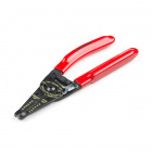
Wire Strippers - 20-30AWG
TOL-14763Suggested Reading
If you aren’t familiar with the following concepts, we recommend checking out these tutorials before continuing.
Light
How to Power a Project
Light-Emitting Diodes (LEDs)
Electric Power
How to Work with Jumper Pads and PCB Traces
Hardware Overview
I/O Pins
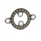
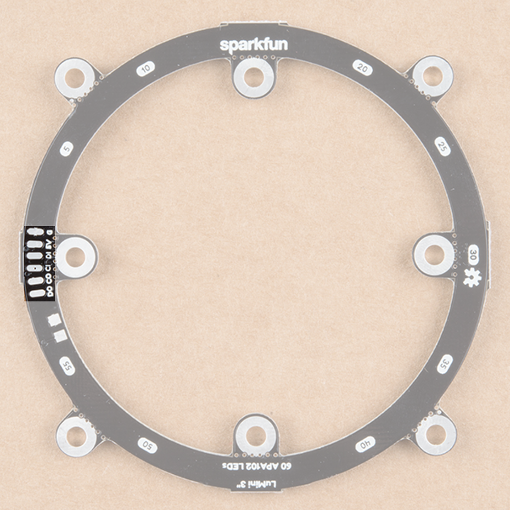
The LuMini rings are powered and controlled using a few pads on the back of each board. Each board has a set of pads for 5V and ground, a set of pads for data and clock input, and a set of pads for data and clock output. These pads are outlined in the below image.
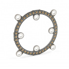
Decoupling Capacitor Pads
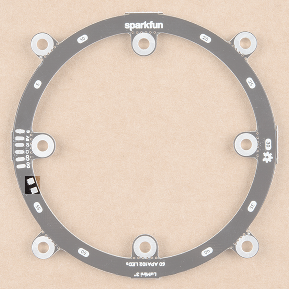
In larger installations you may need to add a decoupling capacitor between power and ground to prevent voltage dips when turning on a whole bunch of LED's simultaneously. The spot to add this optional capacitor is outlined below.
We'd recommend the surface mount 4.7 µF capacitor that is shown below. If you've never done surface mount soldering before, this part might be a little tricky, but check out our SMD tips and tricks on doing just that.
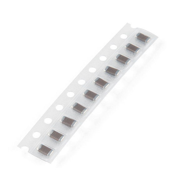
Capacitor 4.7uF - SMD (Strip of 10)
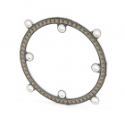
COM-15169LED Numbers
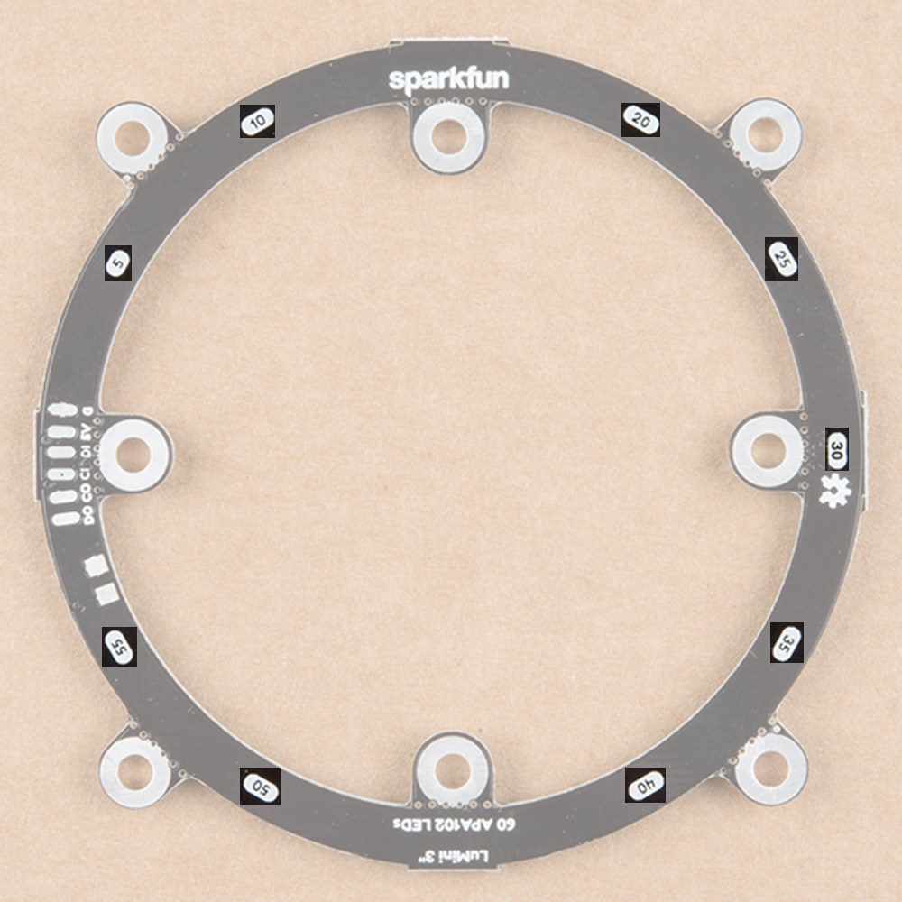
Looking at the back of each ring, you'll also see some numbers. Since the ring acts like a string of LEDs, these numbers correspond to the LED number in the string. Note that, like the led array, we index at LED 0, so calling leds[5] will correspond to the LED on the opposite side of the 5 labeling.
32 is good for testing, as it's a little easier on the eyes. However, turning the brightness up all the way and leaving all LED's on white will result in damage to your ring! Be careful to make sure your animations don't run too hot, and if they do, you can always lower the brightness.
Hardware Assembly
Soldering to the LuMini Rings
Soldering wires to the pads on the LuMini rings is pretty simple. The trick is simply to pre-solder both the pad and stripped wire before attempting to solder the two together. Then, press the wire onto the pad and solder away! Check out the below GIF if you're a little confused.
Choosing Pins
The APA102 LED is controlled on an SPI-like protocol, so it's generally good practice to connect CI to SCLK on your microcontroller, and connect DI to MOSI. However, This setup isn't required, and you can connect data and clock up to most pins on your microcontroller. Go ahead and determine which pins you will use, and solder your Data (DI) and Clock (CI) lines into your microcontroller.
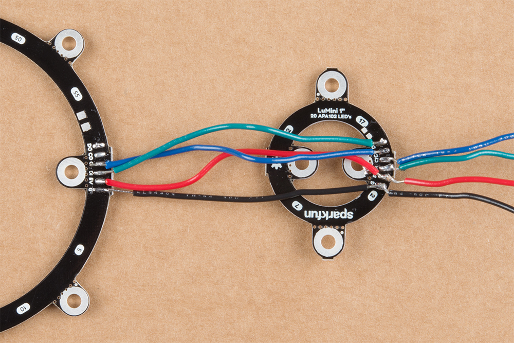
Now that we know how to solder to these pads, we can start making a chain of LuMini rings, or even chain them to other APA102 based products. To do this, all we'll need to do is solder CO and DO of one ring to the CI and DI of the next ring. The below image has the output of a 1 inch ring connected to the input of a 3 inch ring.
Software Installation
Note: This example assumes you are using the latest version of the Arduino IDE on your desktop. If this is your first time using Arduino, please review our tutorial on installing the Arduino IDE. If you have not previously installed an Arduino library, please check out our installation guide.
We'll be leveraging the ever popular FastLED library to control our LuMini rings. You can obtain these libraries through the Arduino Library Manager. Search for FastLED to install the latest version. If you prefer downloading the libraries manually, you can also grap them from the GitHub Repository:
Light It Up
SparkFun has also written some example code specific to the rings to get you started. These example sketches can be found in the LuMini 3-Inch GitHub Repo under Firmware. To download, click on the button below.
Make sure to adjust the pin definition depending on how you connected the LEDs to your microcontroller.
Example 1 --- Ring Test
Glen Larson invented the Larson Scanner as an LED effect for the TV series Knight Rider. In this example, we'll reproduce it, only we'll add in some color for good measure. The Larson Scanner is a great and colorful way to test all of your LEDs on your ring. We'll first begin by creating an object for our ring. Simply uncomment the proper number of LED's for your ring of choice. For these examples, we'll be using the 3 inch ring.
language:c
#include <FastLED.h>

// How many leds in your strip? Uncomment the corresponding line
#define NUM_LEDS 60 //3 Inch
//#define NUM_LEDS 40 //2 Inch
//#define NUM_LEDS 20 //1 Inch

// The LuMini rings need two data pins connected
#define DATA_PIN 16
#define CLOCK_PIN 17

// Define the array of leds
CRGB ring[NUM_LEDS];
We'll then initialize a ring using the .addLeds function below. Notice the BGR in this statement, this is the color order, sometimes, the manufacturer will change the order in which the received data is put into the PWM registers, so you'll have to change your color order to match. The particular chipset we're using is BGR, but this could change in the future. We'll also set the global brightness to 32.
language:c
void setup() {
  LEDS.addLeds<APA102, DATA_PIN, CLOCK_PIN, BGR>(ring, NUM_LEDS);
  LEDS.setBrightness(32);
}
32 is good for testing, as it's a little easier on the eyes. However, turning the brightness up all the way and leaving all LED's on white will result in damage to your ring! Be careful to make sure your animations don't run too hot, and if they do, you can always lower the brightness.
Our animation is then contained in the fadeAll() function, which loops through every LED and fades it to a percentage of it's previous brightness. Our loop() then set's an LED to a hue, increments the hue, and then shows our LEDs. After this, we use the fadeAll() function to fade our LED's down so they don't all end up being on.
lanuage:c
void fadeAll() {
  for (int i = 0; i < NUM_LEDS; i++)
  {
    ring[i].nscale8(250);
  }
}

void loop() {
  static uint8_t hue = 0;
  //Rotate around the circle
  for (int i = 0; i < NUM_LEDS; i++) {
    // Set the i'th led to the current hue
    ring[i] = CHSV(hue++, 150, 255); //display the current hue, then increment it.
    // Show the leds
    FastLED.show();
    fadeAll();//Reduce the brightness of all LEDs so our LED's fade off with every frame.
    // Wait a little bit before we loop around and do it again
    delay(5);
  }
}
Your code should look like the GIF below if you've hooked everything up right. If thing's aren't quite what you'd expect, double check your wiring.
Example 2 --- RGB Color Picker
In this second example, we'll use the serial terminal to control the color displayed by the ring. We initialize everything in the same way. We then listen for data on the serial port, parsing integers that are sent from the serial terminal on your desktop and putting them in the corresponding color (red, green or blue). The code to accomplish this is shown below.
language:c
#include <FastLED.h>

// How many leds in your strip?
#define NUM_LEDS 60 //3 Inch
//#define NUM_LEDS 40 //2 Inch
//#define NUM_LEDS 20 //1 Inch

//Data and Clock Pins
#define DATA_PIN 16
#define CLOCK_PIN 17

CRGB color;
char colorToEdit;

// Define the array of leds
CRGB ring[NUM_LEDS];

void setup() {
  Serial.begin(115200);
  Serial.println("resetting");
  LEDS.addLeds<APA102, DATA_PIN, CLOCK_PIN, BGR>(ring, NUM_LEDS);
  LEDS.setBrightness(32);

  //Display our current color data
  Serial.print("Red Value: ");
  Serial.println(color[0]);
  Serial.print("Green Value: ");
  Serial.println(color[1]);
  Serial.print("Blue Value: ");
  Serial.println(color[2]);
  Serial.println();
}

void loop()
{
  if (Serial.available()) //Check to see if we have new Serial data.
  {
    colorToEdit = Serial.read();
    switch (colorToEdit)
    {
      case 'R':
      case 'r':
        color[0] = Serial.parseInt();
        break;
      case 'G':
      case 'g':
        color[1] = Serial.parseInt();
        break;
      case 'B':
      case 'b':
        color[2] = Serial.parseInt();
        break;
    }
    //Display our current color data
    Serial.print("Red Value: ");
    Serial.println(color[0]);
    Serial.print("Green Value: ");
    Serial.println(color[1]);
    Serial.print("Blue Value: ");
    Serial.println(color[2]);
    Serial.println();
    for (int i = 0; i < NUM_LEDS; i++)
    {
      ring[i] = color;
      FastLED.show();
      delay(10);
    }
  }
}
Go ahead and upload this code, then open your serial monitor to 115200. It should be displaying the current color value (R:0, G:0, B:0), if not.
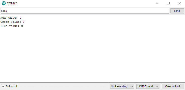
Changing the value of a color is done be sending the letter of the color (R, G, or B) followed by a value between 0 and 255. For instance, turning red to half brightness would be achieved by sending R127. Play around and look for your favorite color.
Example 3 --- HSV Color Picker
The third example is very similar to the first in that we are picking colors using the serial terminal. However, in this example, we are working with an HSV color space. This sketch works mostly the same as the previous one, only we send h, s or v instead of r, g or b. Upload the below code and play around in search of your favorite color.
language:c
#include <FastLED.h>

// How many leds in your strip?
#define NUM_LEDS 60 //3 Inch
//#define NUM_LEDS 40 //2 Inch
//#define NUM_LEDS 20 //1 Inch

//Data and Clock Pins
#define DATA_PIN 16
#define CLOCK_PIN 17

CHSV color = CHSV(0, 255, 255);
char colorToEdit;

// Define the array of leds
CRGB ring[NUM_LEDS];

void setup() {
  Serial.begin(115200);
  Serial.println("resetting");
  LEDS.addLeds<APA102, DATA_PIN, CLOCK_PIN, BGR>(ring, NUM_LEDS);
  LEDS.setBrightness(32);

  //Display our current color data
  Serial.print("Hue: ");
  Serial.println(color.hue);
  Serial.print("Saturation: ");
  Serial.println(color.sat);
  Serial.print("Value: ");
  Serial.println(color.val);
  Serial.println();
}

void loop()
{
  if (Serial.available()) //Check to see if we have new Serial data.
  {
    colorToEdit = Serial.read();
    switch (colorToEdit)
    {
      case 'H':
      case 'h':
        color.hue = Serial.parseInt();
        break;
      case 'S':
      case 's':
        color.sat = Serial.parseInt();
        break;
      case 'V':
      case 'v':
        color.val = Serial.parseInt();
        break;
    }
    //Display our current color data
    Serial.print("Hue: ");
    Serial.println(color.hue);
    Serial.print("Saturation: ");
    Serial.println(color.sat);
    Serial.print("Value: ");
    Serial.println(color.val);
    Serial.println();

    for (int i = 0; i < NUM_LEDS; i++)
    {
      ring[i] = color;
      FastLED.show();
      delay(10);
    }
  }
}
Once again, play around to try and find your favorite color. I find that HSV is a much more intuitive space to work in than RGB space.
Example 4 --- Angle Assignment
In this example, we'll assign the LED's in our circle to the angles of the unit circle so we won't have to think about which LED corresponds to which angle. We're also going to use 0-255 instead of 0-360, as this makes more sense from a computer standpoint. For example, the LED's at 90° would be accessed by calling ringMap[64]. This is accomplished using the populateMap() function, which populates the uint8_t ringMap[255] object. The populateMap() function is shown below and gets called in our setup() loop.
language:c
#include <FastLED.h>

// How many leds in your strip?
#define NUM_LEDS 60 //3 Inch
//#define NUM_LEDS 40 //2 Inch
//#define NUM_LEDS 20 //1 Inch

//Data and Clock Pins
#define DATA_PIN 16
#define CLOCK_PIN 17

// Define the array of leds
CRGB ring[NUM_LEDS];
uint8_t ringMap[255];
uint8_t rotation = 0;

float angleRangePerLED = 256.0 / NUM_LEDS; //A single LED will take up a space this many degrees wide.

void populateMap () //we map LED's to a 360 degree circle where 360 == 255
{
  for (int ledNum = 0; ledNum < NUM_LEDS; ledNum++) //Loops through each LED and assigns it to it's range of angles
  {
    for (int j = round(ledNum * angleRangePerLED); j < round((ledNum + 1) * angleRangePerLED); j++)
    {
      ringMap[j] = ledNum;
    }
  }
}

void fadeAll(uint8_t scale = 250)
{
  for (int i = 0; i < NUM_LEDS; i++)
  {
    ring[i].nscale8(scale);
  }
}

void setup()
{
  Serial.begin(115200);
  FastLED.addLeds<APA102, DATA_PIN, CLOCK_PIN, BGR>(ring, NUM_LEDS);
  FastLED.setBrightness(32);
  populateMap();
}
In our loop, we'll map each angle of the circle to a hue, then we'll light up 3 pixels, each separated by 120° We do this by lighting an LED at a starting angle 0, then add 120° which corresponds to 85.333 ((120/360)*255 = 85.333) and light the LED at this angle. We repeat the same process to light the final LED. Each angle is matched to a hue, so we should see the same colors in each position.
language:c
void loop()
{
  for (int i = 0; i < 3; i++)
  {
    uint8_t angle = round(i * 85.3333) + rotation;
    ring[ringMap[angle]] = CHSV(angle, 127, 255);
  }
  FastLED.show();
  rotation++;
  fadeAll(248);
  delay(5);
}
Notice how ringMap[angle] is called within ring, as it will return the LED number at that angle. Uploading this code should look similar to the below GIF
Example 5 --- Using Gradients
In this final example, we'll leverage FastLED's palette object (CRGBPalette16) to create and visualize a color palette on our ring. We have much the same initialization as our previous examples, only this time we also initialize a CRGBPalette16 object which will be full of colors along with a TBlendType which will tell us whether or not to blend the colors together or not. This can be either LINEARBLEND or NOBLEND. To populate this gradient, we use examples 2 and 3 to find the colors we want to put into our gradient. The gradient included is a bunch of colors created in HSV space, but you can easily change to RGB space if you prefer. You can also use any of the preset palettes by uncommenting the line that sets it equal to currentPalette.
language:c
TBlendType    currentBlending = LINEARBLEND;
CRGBPalette16 currentPalette = {
  CHSV(5, 190, 255),
  CHSV(0, 190, 255),
  CHSV(245, 255, 255),
  CHSV(235, 235, 255),
  CHSV(225, 235, 255),
  CHSV(225, 150, 255),
  CHSV(16, 150, 255),
  CHSV(16, 200, 255),
  CHSV(16, 225, 255),
  CHSV(0, 255, 255),
  CHSV(72, 200, 255),
  CHSV(115, 225, 255),
  CHSV(40, 255, 255),
  CHSV(35, 255, 255),
  CHSV(10, 235, 255),
  CHSV(5, 235, 255)
};

//currentPalette = RainbowColors_p;
//currentPalette = RainbowStripeColors_p;
//currentPalette = OceanColors_p;
//currentPalette = CloudColors_p;
//currentPalette = LavaColors_p;
//currentPalette = ForestColors_;
//currentPalette = PartyColors_p;
We then use the ColorFromPalette function to put the colors from our gradient onto our LED ring. Notice how we use the angle functions once again to map each part of the gradient to an angle.
language:c
void loop() {
  for (uint8_t i = 0; i < 255; i++)
  {
    uint8_t gradientIndex = i + rotation;
    ring[ringMap[i]] = ColorFromPalette(currentPalette, gradientIndex, brightness, currentBlending);
  }
  FastLED.show();
  rotation++;
  delay(20);
}
Play around with the colors in your palette until you're satisfied. If all is hooked up correctly your ring should look something like the below GIF.
Additional Examples
There are quite a few additional examples contained in the FastLED library. While they aren't made specifically for the rings, they can still show you some useful features in the FastLED library, and may give you some ideas for some animations of your own.
If the FastLED library is installed, they can be found from the Arduino IDE menu by opening up File -> Examples -> Examples From Custom Libraries -> FastLED .
Resources & Going Further
Now that you've successfully got your LuMini Ring up and running, it's time to incorporate it into your own project! For more information about the LuMini Ring, check out the links below.
Lumini Ring 3 Inch
Lumini Ring 2 Inch
Lumini Ring 1 Inch
- Datasheet - APA102 (PDF)
- SMD Soldering Tips and Tricks
- GitHub FastLED Arduino Library
- GitHub Code -- Example used in this tutorial can be found in the LuMini Ring 3 Inch Repo
- SFE Product Showcase
Looking for a different way of controlling the LuMini Rings? Check out the LuMini Drive to program the APA102's in Circuit Python.
LumiDrive Hookup Guide
Need some inspiration for your next project? Check out some of these related tutorials:
Vibe-O-Matic 3000
Motion Controlled Wearable LED Dance Harness
Wireless Glove Controller
Qwiic SHIM Kit for Raspberry Pi Hookup Guide
Or check out these blog post: