LumiDrive Hookup Guide
Introduction
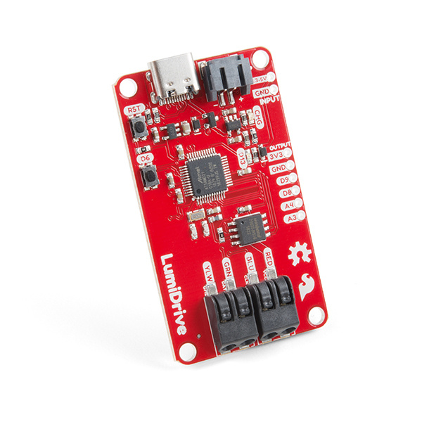
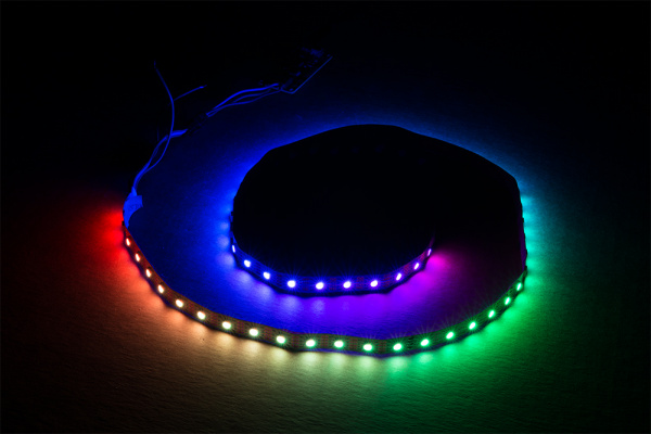
LumiDrive is SparkFun's foray into all things Python on microcontrollers. Leveraging Adafruit's Circuit Python, we have created a product made for driving a strand of APA102's. We've broken out a few analog and digital pins from the onboard SAMD21G-AU microcontroller so that you can implement external buttons, switches, and other whizzbangs to interact with the LEDs.
Circuit Python
You can read the extensive documentation about Circuit Python here on Adafruit's website, but let's review a short and sweet version. Circuit Python is Adafruit's version of MicroPython. What pray tell, is MicroPython? MicroPython is Python 3 for microcontrollers. MicroPython takes the power of the wildly popular Python interpreted language that is easy to use, easy to read, and powerful and makes it usable for microcontrollers. It feels familiar in the way you declare and use pins but unlike Arduino, you don't have to compile or upload your code. This is because your microcontroller acts like a USB drive when you plug it into your computer. The code simply lives as a file that you modify directly and when it's saved, it is automatically loaded. Algebraic! It's also compatible with the Python 3 you have on your computer so that you can develop seamlessly on your desktop! Why are we using Circuit Python? Circuit Python has the advantage of having many libraries built in by default that are catered toward entry-level hobbyists. In the case of the LumiDrive, we'll be utilizing the DotStar library, Adafruit's library for APA102 LEDs.
Required Materials:
We have many portable options to power your LEDs:
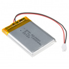
Lithium Ion Battery - 1Ah
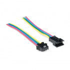
PRT-13813I found this connector to be very helpful because it kept me from plugging and unplugging different strands of APA102's directly into the poke-home connectors.
Suggested Reading
Battery Technologies
Light-Emitting Diodes (LEDs)
Mean Well LED Switching Power Supply Hookup Guide
LuMini Ring Hookup Guide
Hardware Overview
Power
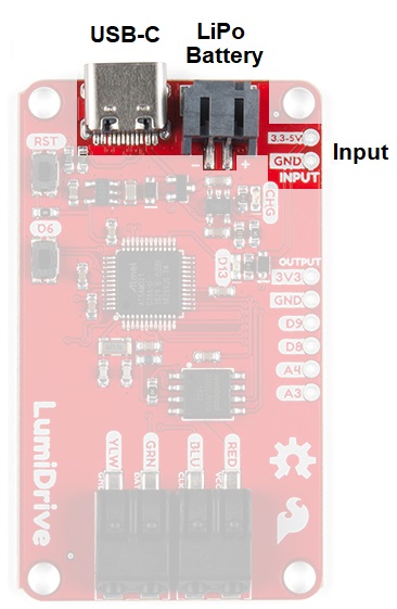
There are three options for power on the product: USB-C, Lithium Ion Battery, or Input. You can provide power in the range from 3.3V-6V.
USB-C
USB-C, aside from being reversible which is already awesome, has the capability of supplying more power than its predecessor. I was able to pull 2 AMPs from my computer on a 3.1 USB plug. Be cautious - I did this so that you don't have to! Every computer is different and I strongly advise that you don't do something so rash unless you are absolutely confident. Also keep in mind that different USB ports (2.0, 3.0, and 3.1) supply different levels of power. 3.1 is easy to identify because it has a blue tongue when you look into the port.
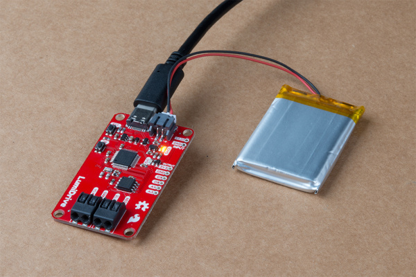
Lithium Ion Battery
We have many options in our catalog that will suit your various portable power needs. LumiDrive also comes with a charging circuit so you can charge your LiPo battery.
Two Pin Input Headers
Last but not least is a 2 pin header labeled INPUT where you can supply your own power.
Current Draw
The table below lists the current draw for a strand of 55 LEDs at full white at half and full brightness. I've also included current draw for the various included functions at varying LED amounts and brightness to help you make more educated decisions when purchasing or using your LEDs.
| # of LEDs (Half Brightness) | Current Consumption (Amps) |
|---|---|
| 1 | 0.070 |
| 2 | 0.095 |
| 3 | 0.120 |
| 5 | 0.139 |
| 10 | 0.289 |
| 20 | 0.536 |
| 30 | 0.755 |
| 35 | 0.883 |
| 40 | 1.102 |
| 50 | 1.311 |
| # of LEDs (Full Brightness) | Current Consumption (Amps) |
| 10 | 0.520 |
| 15 | 0.737 |
| 25 | 1.328 |
| 27 | 1.426 |
| 29 | 1.523 |
| 31 | 1.618 |
| 40 | 2.018 |
| Function at 55 LEDs | Current Consumption (Amps) |
| Slice Rainbow (0.25 Brightness) | 0.336 |
| Slice Rainbow (0.50 Brightness) | 0.600 |
| Rainbow Cycle (0.25 Brightness) | 0.281 |
| Rainbow Cycle (0.50 Brightness) | 0.500 |
| Function at 85 LEDs | Current Consumption (Amps) |
| Slice Rainbow (0.25 Brightness) | 0.500 |
| Slice Rainbow (0.50 Brightness) | 0.890 |
| Rainbow Cycle (0.25 Brightness) | 0.425 |
| Rainbow Cycle (0.50 Brightness) | 0.727 |
Input Output
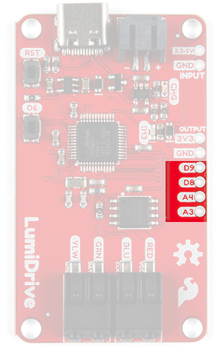
There are four input/output pins broken out to the side of the product. There are two digital pins and two analog pins. These can be used to interact with your LED strand (or not) by attaching buttons, switches, light sensors, etc.
Buttons
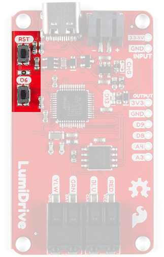
There are two buttons on the product. The top button is a reset button which will reset the board on press. The second is a button attached to digital pin D6. You can use this in place of attaching a button to the board.
LEDs
There are two LEDs on board. The top LED in the picture is a yellow charge LED that indicates that a LiPo battery is being charged. The second is a blue stat LED attached to pin D13.
Poke-home Connectors
There are two Poke-home connectors at the bottom of the product.
They are versatile and rather robust and allow you to plug in wire without the need for solder. They're labeled with the color of wire that is used in the strands of APA102 LEDs that we sell here at SparkFun but are not limited to just those. Just below that silk you'll notice the function of those lines are labeled as in the following chart.
| Pin | Description |
|---|---|
| RED | VCC (3.3-5V) |
| BLU | Clock |
| GRN | Data |
| YELLOW | Ground |
Hardware Assembly
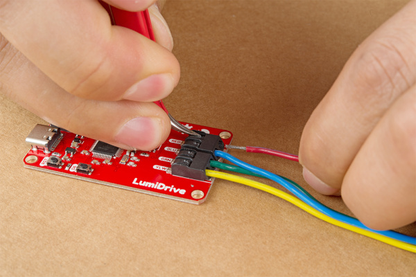
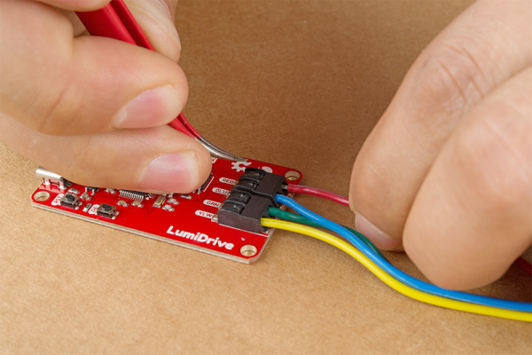
Hardware assembly is straight forward. Let's start by plugging your LED strand into the poke-home connectors. Finer control can be achieved by using a pair of tweezers or the tip of a pen to press in the flap on the topside of the poke-home connector. Here we've opted for tweezers since that's what we had handy.
When you press onto the black flap on the top of the poke-home connector, two metal wedges move laterally - to the sides of the product- inside the connector. Push your wire into the poke-home connector. When you release it, the two wedges will clamp down onto the wire. Give them a slight tug to make sure the wires are in there solid. You're ready to rock!
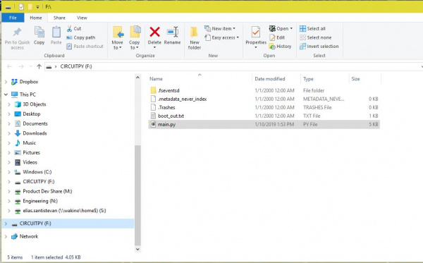
Plug your LumiDrive into your computer with the USB-C connector. It should pop up automatically as a hard drive called CIRCUITPY. If it doesn't pop up automatically, unplug it and plug it back in. If that doesn't work, navigate to your files folder and look for CIRCUITPY on the left hand side and give it a click. At this point the blue stat LED on the LumiDrive should be blinking. From here you can open up that CIRCUITPY by clicking on it.
Let's move onto the example code.
Python Example Code
Your LumiDrive should already come with the following Python code but in case something happens to it, than you can re-download the example code here:
If you do want to go the Arduino route, you'll need to install the FastLED library. See our LuMini Ring Hookup Guide for installation details and example code.
Before we begin, let's talk about the options for loading and updating this code on your LumiDrive. One option is to move the file main.py onto your desktop and edit it with a text editor. When you're done with it, you can simply drag and drop it back into the CIRCUITPY drive. Circuit Python will recognize the change and automatically load the new code. The other option is to edit the file directly in the CIRCUITPY drive. This option is much more convenient and efficient, but requires a text editor that writes the file completely when it's saved. On Windows not all text editors exhibit the necessary behavior. Below is a list of good, not great, and not recommended text editors for editing files directly on LumiDrive (or any Circuit Python board). If you're using a Mac then you won't be running into any of these issues.
| GOOD | GOOD only with ADD-ONS | NOT Recommended |
|---|---|---|
| MU | PYCharm IDE | Notepad/Notepad++ |
| VIM | Atom | IDLE |
| EMACS | Slick Edit | Nano |
| Sublime Text | ||
| Visual Studio Code |
My suggestion would be to use MU or Sublime Text. The first is more beginner friendly while the second is more light weight with some really nice features. If you're already familiar with VIM, EMACS, or Visual Studio Code then use those instead.
If you're attached to one of the not recommended editors then there is a way to get it to work. After you've made changes to the main.py, if you eject the CIRCUITPY drive then it will force Windows to write the saves that you made.
Let's quickly talk about which files Circuit Python monitors for saves. Circuit Python looks for the following four files in this order and runs the first one it finds: code.txt, code.py, main.txt, and main.py. That's all of it, now onto the code.
At the top of the code we have a number of libraries that are necessary for our code.
language:python
import adafruit_dotstar # Our LED library
import digitalio
import board
import math
import time
Here's where you can start to modify the code to your particular LED strip. The num_pixels variable should reflect how many LEDs you have and brightness controls the brightness. We have 60 pixels in the example because it reflects the number of LEDs of our 1m length of APA102s. Keep in mind as you set these that if you're powering through your computer, don't add too many too quickly. Otherwise you could potentially harm your computer. Below our two variables we create an instance of our library called pixels, and just below that we have some pre-defined colors.
language:python
# These two variables should be adjusted to reflect the number of LEDs you have
# and how bright you want them.
num_pixels = 60
brightness = 0.25

# This creates the instance of the DoTStar library.
pixels = adafruit_dotstar.DotStar(board.SCK, board.MOSI,
    num_pixels, brightness=brightness, auto_write=False)

# Some standard colors.
BLACK = (0, 0, 0)
RED = (255, 0, 0)
YELLOW = (255, 150, 0)
ORANGE = (255, 40, 0)
GREEN = (0, 255, 0)
TEAL = (0, 255, 120)
CYAN = (0, 255, 255)
BLUE = (0, 0, 255)
PURPLE = (180, 0, 255)
MAGENTA = (255, 0, 20)
WHITE = (255, 255, 255)

# A list of the ten colors. Use this if you want to cycle through the colors.
colorList = [RED, YELLOW, ORANGE, GREEN, TEAL, CYAN, BLUE, PURPLE, MAGENTA,
                    WHITE]
We have a number of functions to handle different LED behaviors. Each function has a little explanation commented just above it's definition.
language:python
# The travel function takes a color and the time between updating the color. It
# will start at LED one on the strand and fill it with the give color until it
# reaches the maximum number of pixels that are defined as "num_pixels".
def travel(color, wait):
    num_pixels = len(pixels)
    for pos in range(num_pixels):
        pixels[pos] = color
        pixels.show()
        time.sleep(wait)

# The travel_back function like the travel function takes a color and the time between
# updating the color. However it unlike the travel function, it will start at
# the last LED and works its way to LED. Fill the LED with the given color.
def travel_back(color, wait):
    num_pixels = len(pixels)
    for pos in range(num_pixels, 0, -1):
        pixels[pos] = color
        pixels.show()
        time.sleep(wait)

# This function may give you an idea of other functions to create. Here we're
# starting with green LEDs and then slowing filling the red color until we have
# a yellow color.
def green_yellow_wheel(wait):
    for redColor in range(255):
        color = (redColor, 150, 0)
        pixels.fill(color)
        pixels.show()
        time.sleep(wait)

# You can use this function to get a custom color value.
# value much in the form of a tuple, like the colors above.
def wheel(pos):
    # Input a value 0 to 255 to get a color value.
    # The colours are a transition r - g - b - back to r.
    if pos < 0 or pos > 255:
        return (0, 0, 0)
    if pos < 85:
        return (255 - pos * 3, pos * 3, 0)
    if pos < 170:
        pos -= 85
        return (0, 255 - pos * 3, pos * 3)
    pos -= 170
    return (pos * 3, 0, 255 - pos * 3)

# This function takes a color and a dely and fills the entire strand with that color.
# The delay is given in the case you use multiple color fills in a row.
def color_fill(color, wait):
    pixels.fill(color)
    pixels.show()
    time.sleep(wait)

# Fills the strand with two alternating colors and cycles through the 10 colors
def slice_alternating(wait):

    num_pixels = len(pixels)

    pixels[::2] = [RED] * (num_pixels // 2)
    pixels.show()
    time.sleep(wait)
    pixels[1::2] = [ORANGE] * (num_pixels // 2)
    pixels.show()
    time.sleep(wait)
    pixels[::2] = [YELLOW] * (num_pixels // 2)
    pixels.show()
    time.sleep(wait)
    pixels[1::2] = [GREEN] * (num_pixels // 2)
    pixels.show()
    time.sleep(wait)
    pixels[::2] = [TEAL] * (num_pixels // 2)
    pixels.show()
    time.sleep(wait)
    pixels[1::2] = [CYAN] * (num_pixels // 2)
    pixels.show()
    time.sleep(wait)
    pixels[::2] = [BLUE] * (num_pixels // 2)
    pixels.show()
    time.sleep(wait)
    pixels[1::2] = [PURPLE] * (num_pixels // 2)
    pixels.show()
    time.sleep(wait)
    pixels[::2] = [MAGENTA] * (num_pixels // 2)
    pixels.show()
    time.sleep(wait)
    pixels[1::2] = [WHITE] * (num_pixels // 2)
    pixels.show()
    time.sleep(wait)


# This function divides the given number of pixels and fills them as evenly as
# possible with a rainbow pattern (RED, ORANGE, YELLOW, GREEN, BLUE, PURPLE)
# which repeats every 6 LEDs.
def slice_rainbow(wait):

    num_pixels = len(pixels)

    pixels[::6] = [RED] * math.ceil(num_pixels / 6)
    pixels.show()
    time.sleep(wait)
    pixels[1::6] = [ORANGE] * math.ceil((num_pixels - 1) / 6)
    pixels.show()
    time.sleep(wait)
    pixels[2::6] = [YELLOW] * math.ceil((num_pixels -2) / 6)
    pixels.show()
    time.sleep(wait)
    pixels[3::6] = [GREEN] * math.ceil((num_pixels-3) / 6)
    pixels.show()
    time.sleep(wait)
    pixels[4::6] = [BLUE] * math.ceil((num_pixels-4) / 6)
    pixels.show()
    time.sleep(wait)
    pixels[5::6] = [PURPLE] * math.ceil((num_pixels-5) / 6)
    pixels.show()
    time.sleep(wait)


# This function makes a strand of LEDs look like a rainbow flag that travels
# along the length of the strand. It is not infinitely contniuous and will stop
# after any single LED has cycled through every color.
def rainbow_cycle(wait):
    num_pixels = len(pixels)
    for j in range(255):
        for i in range(num_pixels):
            rc_index = (i * 256 // num_pixels) + j
            pixels[i] = wheel(rc_index & 255)
        pixels.show()
        time.sleep(wait)

print("Clearing LEDs.")
color_fill(BLACK,0)
Finally we have a while loop that is akin to void loop in Arduino. Right now we have the loop blinking our blue D13 stat LED.
language:python
#Ah trusty ol' blink.
while True:
    led.value = True
    time.sleep(.5)
    led.value = False
    time.sleep(.5)
Instead, let's pick some functions from the functions above and type them in. I chose the following and gave the function its' necessary parameter: a delay time.
language:python
while True:
    rainbow_cycle(0)
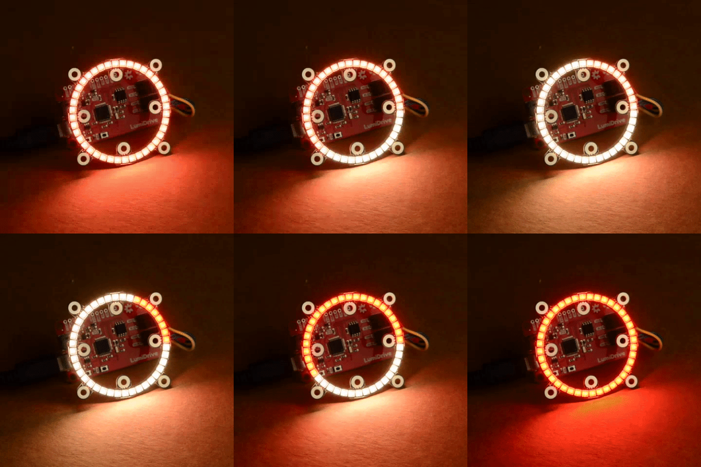
After you've modified the code, just hit save (assuming you have the correct text editor for saving directly on LumiDrive) and the code will automatically run. If all is well you should see the following:
Algebraic!
Using the 3 inch LuMini ring, and a couple other functions.
Read-Evaluate-Print-Loop (REPL)
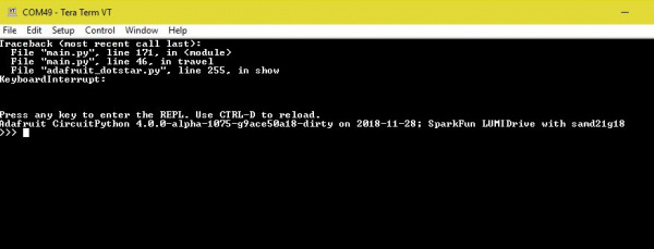
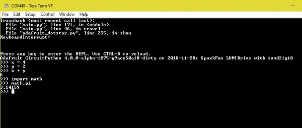
A note about the Read-Evaluate-Print-Loop, or the REPL. It's a language shell that allows you to interact with the LumiDrive in an Interactive Python environment. If you pull up your favorite serial program and open it to the COM port of the LumiDrive you should see the following.
Main.py will be running an infinite blink loop fresh out of the box. Simply press CTRL-C to interrupt the code. Here you have an interactive python environment to play around in.! Here we can do some fun things like Math!
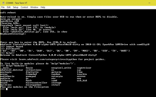
More importantly we can see what libraries and pins are available to us in the version of Circuit Python that is loaded on your LumiDrive, using the help(modules) and dir(board) commands respectively.
If you look at the line that says dir(board), just below are various pins that are available in Circuit Python but not all of them are physically broken out on the board. When you're done messing around in REPL and ready to run the code that is on your LumiDrive, you can press CTRL-D and that will initiate a soft reboot.
Resources and Going Further
- Hardware
- Circuit Python
- Micro Python
- GitHub Repo
- Product - Hardware
- Example Code -- Repo with the example code from this tutorial.
Need more inspiration? Check out some of these tutorials:
FemtoBuck Constant Current LED Driver Hookup Guide v13
MAX30105 Particle and Pulse Ox Sensor Hookup Guide
LP55231 Breakout Board Hookup Guide
RedBoard Edge Hookup Guide
Or check out these blog post:
