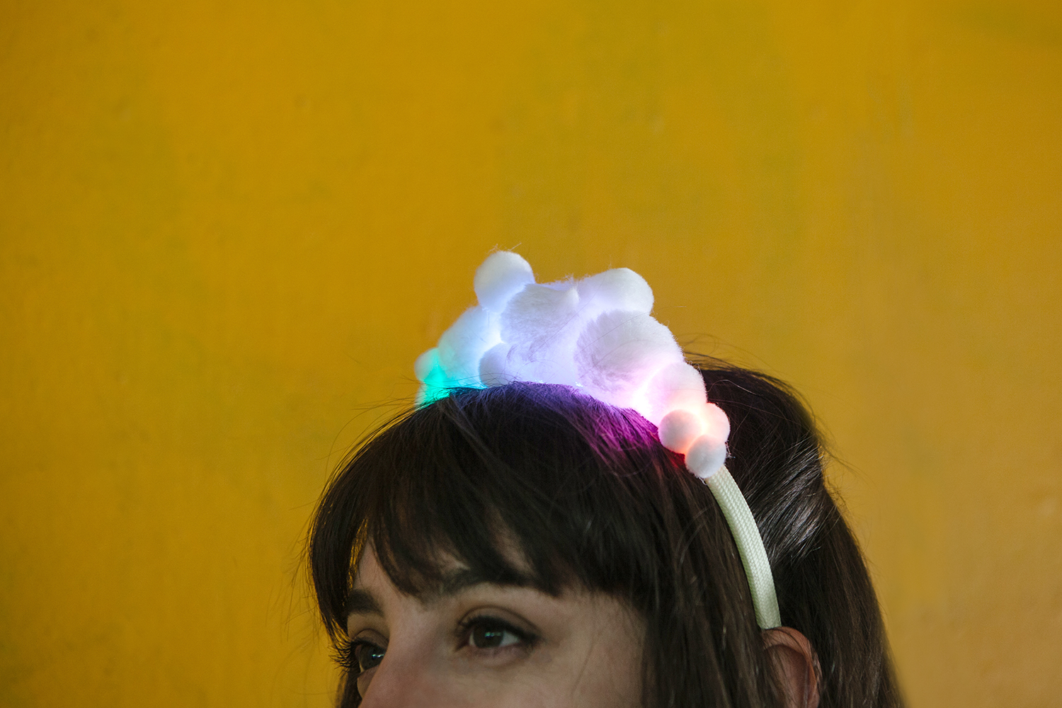
LED PomPom Headbands
 Feldi
Feldi 
Introduction
Design and build time for each project: 30 minutes — 1 hour
In this project, we’ll create two versions of a wearable headband - one for beginners and one for more advanced makers. In the beginner project, we will make a simple circuit made of 8x - 10x Super Bright White LEDs wired in parallel and powered by a single rechargeable LiPo Battery.

In the more advanced project, we will make a more complicated programmable circuit using addressable LEDs, Arduino Pro Mini 5V/16MHz, and two LiPo batteries wired in parallel.
Suggested Reading
Before you get started with the beginner's version, take some time to familiarize yourself with the following:
How to Solder: Through-Hole Soldering
What is a Circuit?
How to Power a Project
Light-Emitting Diodes (LEDs)
Series and Parallel Circuits
In order to follow along with the more advanced version, ensure that you are familiar with the following as well:
Installing an Arduino Library
What is an Arduino?
Installing Arduino IDE
Using the Arduino Pro Mini 3.3V
WS2812 Breakout Hookup Guide
Materials and Tools
Let's go over all of the things you'll need to solder your project together.
Items required for the beginner LED PomPom Headband project:
Items required for the advanced LED PomPom Headband project:
For both options, you will also need the following supplies:
- Headbands (can be found at your local drugstore)
- PomPoms (available at most local craft stores)
- Hot glue gun (with extra glue)
- Double stick tape
- Soldering Iron
- Solder
- Hook up Wire (Black, Red, and White)
- Flush Cutters
- Wire Strippers
Understanding Your Circuit
The beginner PomPom Headband project is an example of a basic circuit – an electrical loop that travels from a power source along a path (i.e. wires, traces, or any conductive materials), through one or more component(s), and then back to the power source. For our project, we’ll use LEDs (Light-Emitting Diodes). This electrical loop for the project is completed by soldering the LED's leads together. In order to light the LEDs, electricity from the power source must flow from the positive (+) side of the battery through an LED and back to the negative (–) side of the battery. This electric flow is called current.
In this circuit, the LEDs are soldered in parallel. Take a look at the LEDs, current limiting resistors, and battery in the circuit diagram below. When the LEDs are connected in parallel, all the positive leads will be connected together. The bent leads on the right of the LEDs (anodes +) are connected to VCC on the power source and each other in red. Additionally, the negative leads will share another connection. Notice that the leads on the left of the LEDs (cathodes -) are connected to ground on the power source with a resistor. We used a 47Ω resistor labeled with the yellow-purple-black bands.
It's important to keep in mind that certain electronic components have polarity, meaning electric current can only flow through them in one direction. If hooked up incorrectly, the LEDs will not light up. The battery is also polarized; it has a positive and negative side. Always check the to make sure that all your parts are correctly oriented before soldering together a circuit.

*PLEASE NOTE: Usually, you would want to include a current limiting resistor between the power source and LEDs. In our circuit, we added a 47 Ohm current limiting resistor for each LED. You will want to consider adding a current limiting resistor to safely power the project.
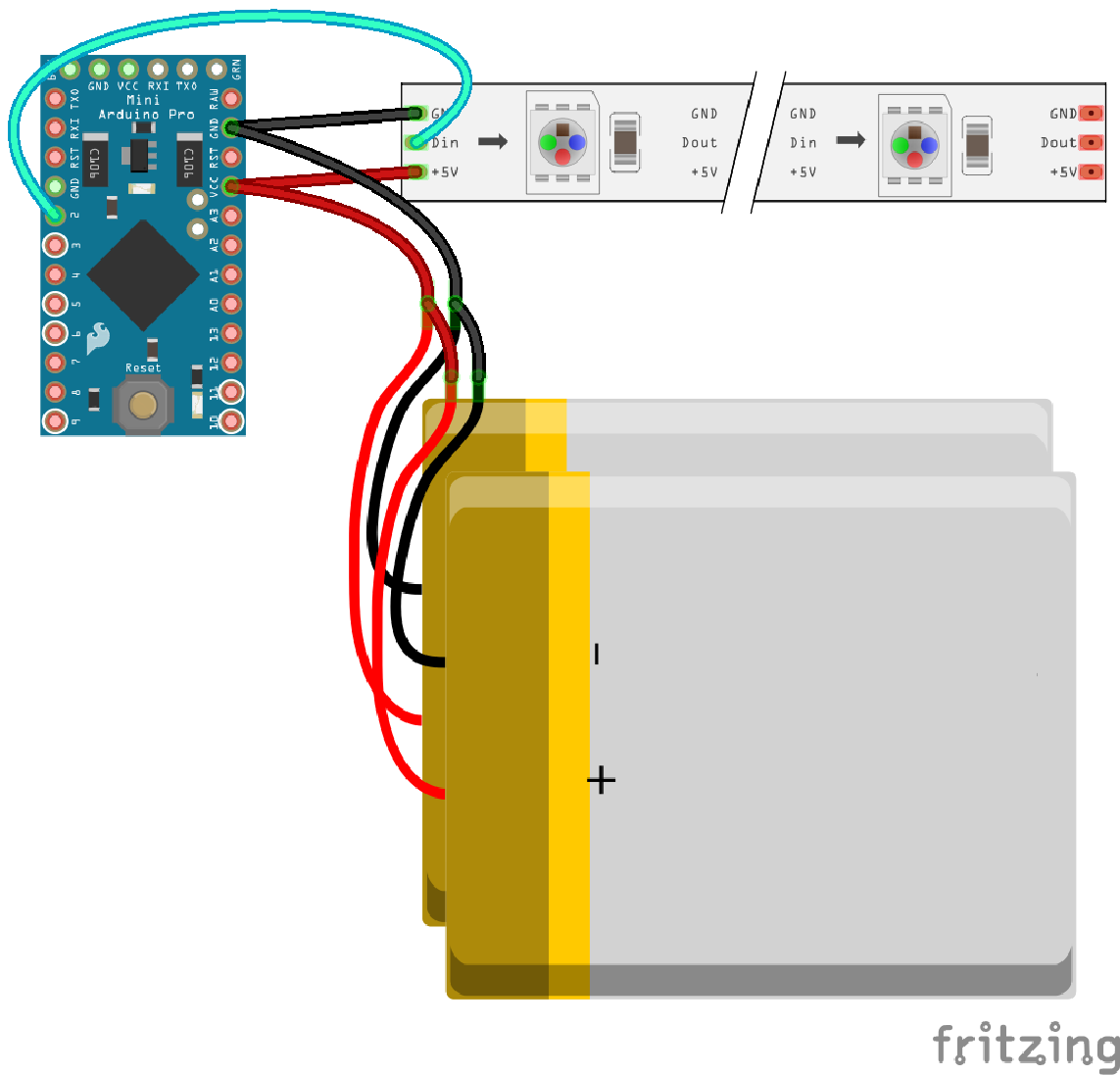
The more advanced PomPom Headband project is a more complex circuit in that we are including a microcontroller - the 5V Arduino Pro Mini. This single board computer is the brains behind this project. The program we upload to the 5V Arduino Pro Mini will dictate the colors of addressable RGB LEDs. The exciting part about this project is that you can change your code as many times as you like to customize the colors for a specific event! Please refer to the below circuit diagram when soldering your parts together.
Beginner PomPom Headband
STEP 1:
Bend the leads of your LEDs to a 90 degree angle. Remember, LEDs have polarity, so make sure they are all facing the same direction.

STEP 2:
Solder a 47Ω Resistor to the cathode of each LED. If you are unsure of which side is the cathode, remember that the LED's cathode side will have a flat edge on the bulb and a shorter leg.
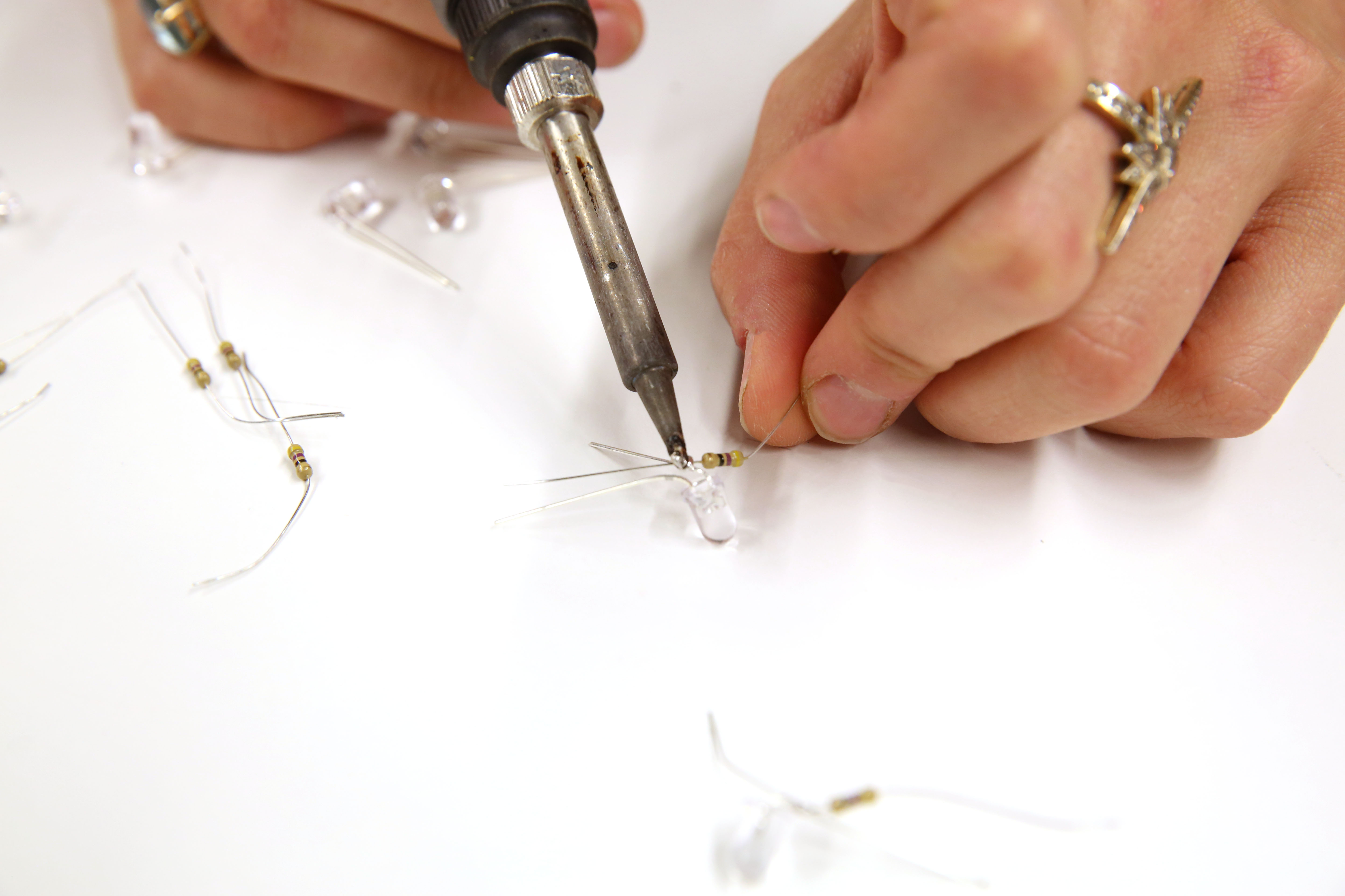
Clip off the excess leads between the resistor and cathode using the flush cutters.

STEP 3:
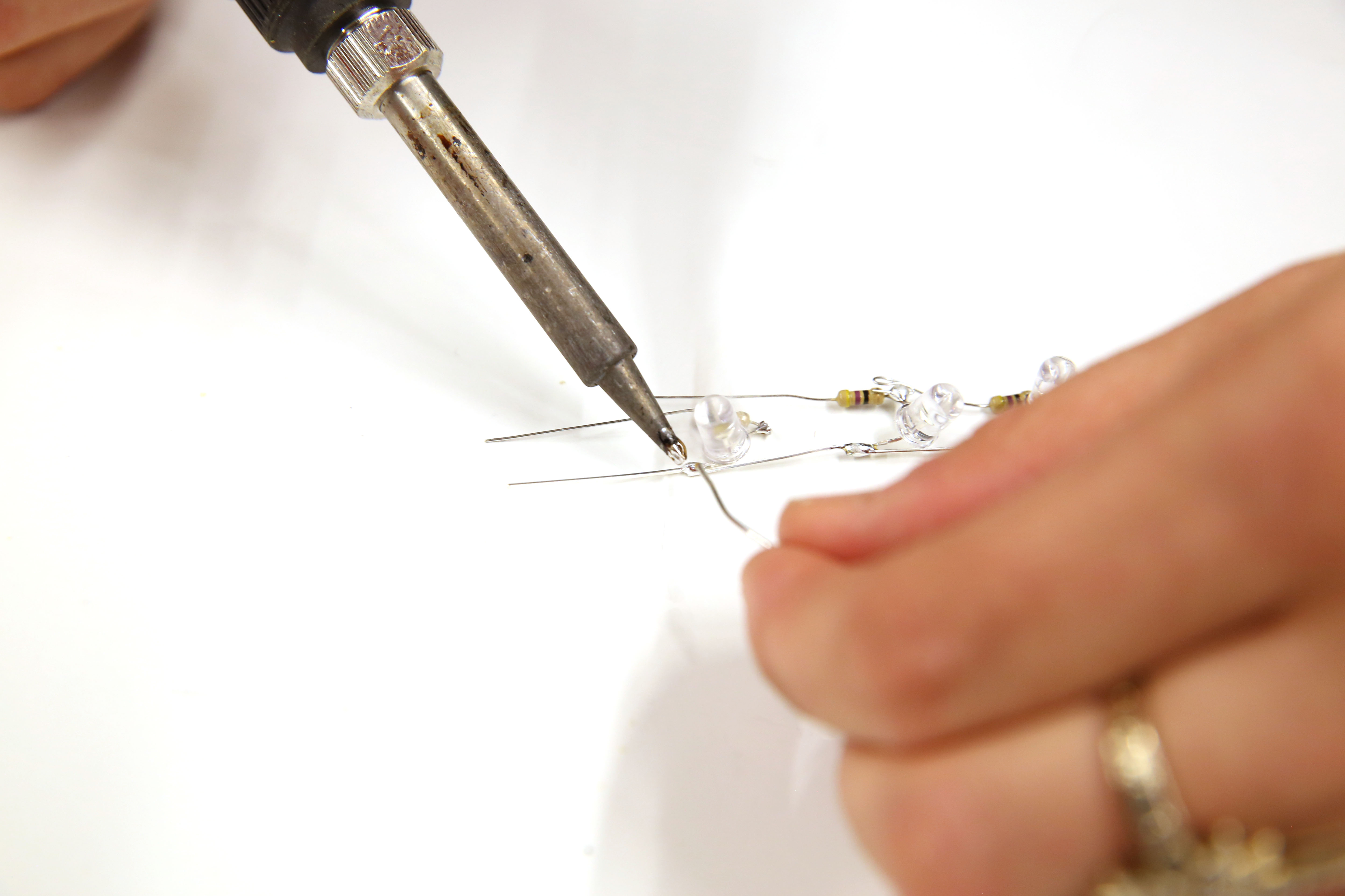
Solder the LEDs together in a parallel chain. All the anodes should be connected together on one side and all of the cathodes should be connected via the resistors on the other side. If any of the LEDs are arranged incorrectly, they will not illuminate when power is applied.
STEP 4:
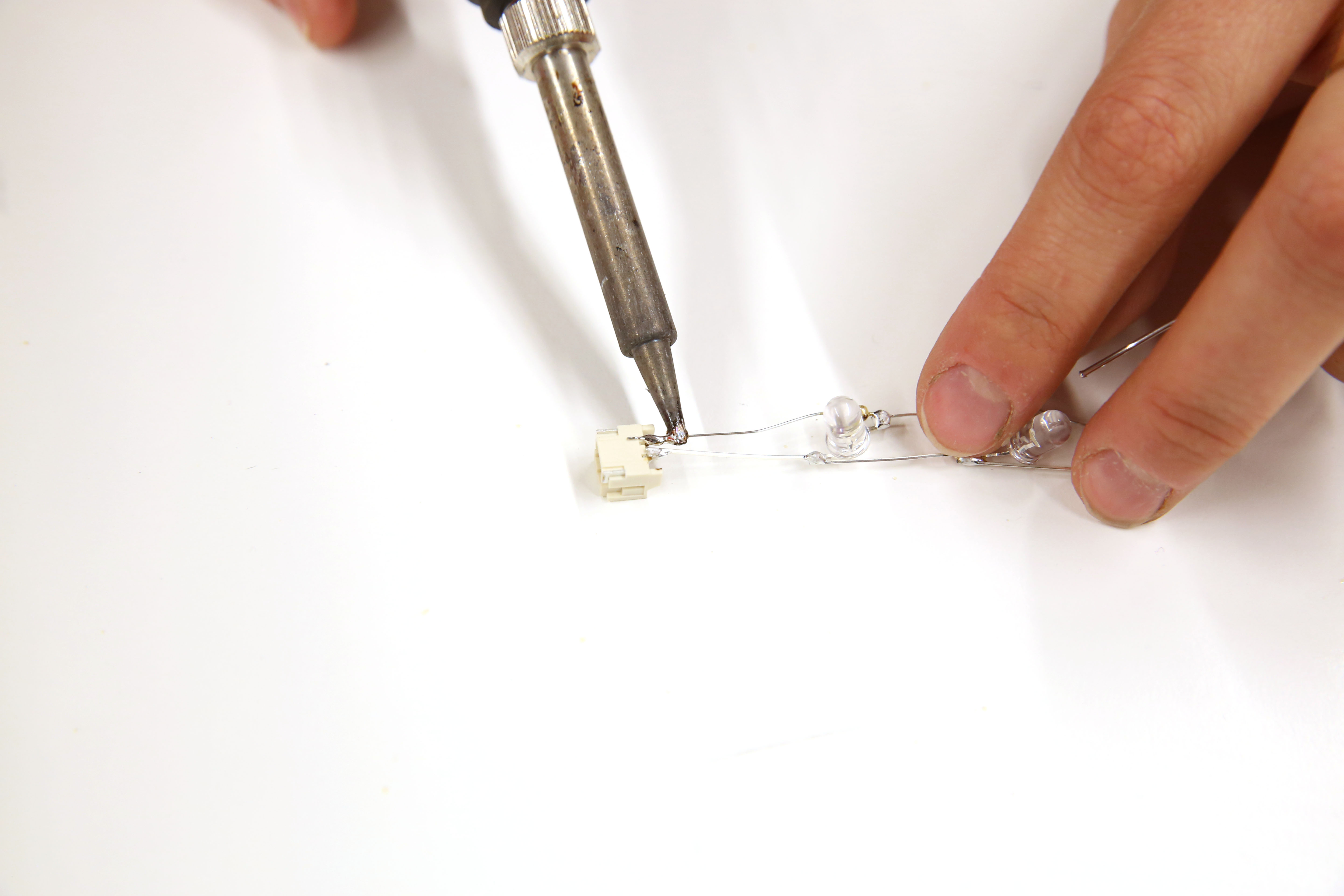
Solder the JST connector to the last LED on the chain. Remember, the battery has a polarity, so make sure that you have the anode and cathode connecting to the correct side of the connector. You can figure this out by sticking the battery inside before soldering. After testing and take note of which side is VCC and ground, remove the battery from the connector and solder the connector.
STEP 5:
Test your circuit again! After soldering, make sure that your circuit is working properly and lighting up before moving on to the next step. To test, plug the battery into the circuit once more to light the LEDs.
STEP 6:
Hot glue the LED chain with the JST connector to the top of your headband.

STEP 7:
Insulate all exposed metal pins with hot glue.
*PLEASE NOTE: The wires need to be completely covered in hot glue. Make sure that metal pins on the anode and cathode side have some space between each other. This is to prevent a circuit short which can cause a fire. It if important for your safety to completely cover any exposed wire with glue.

STEP 8:
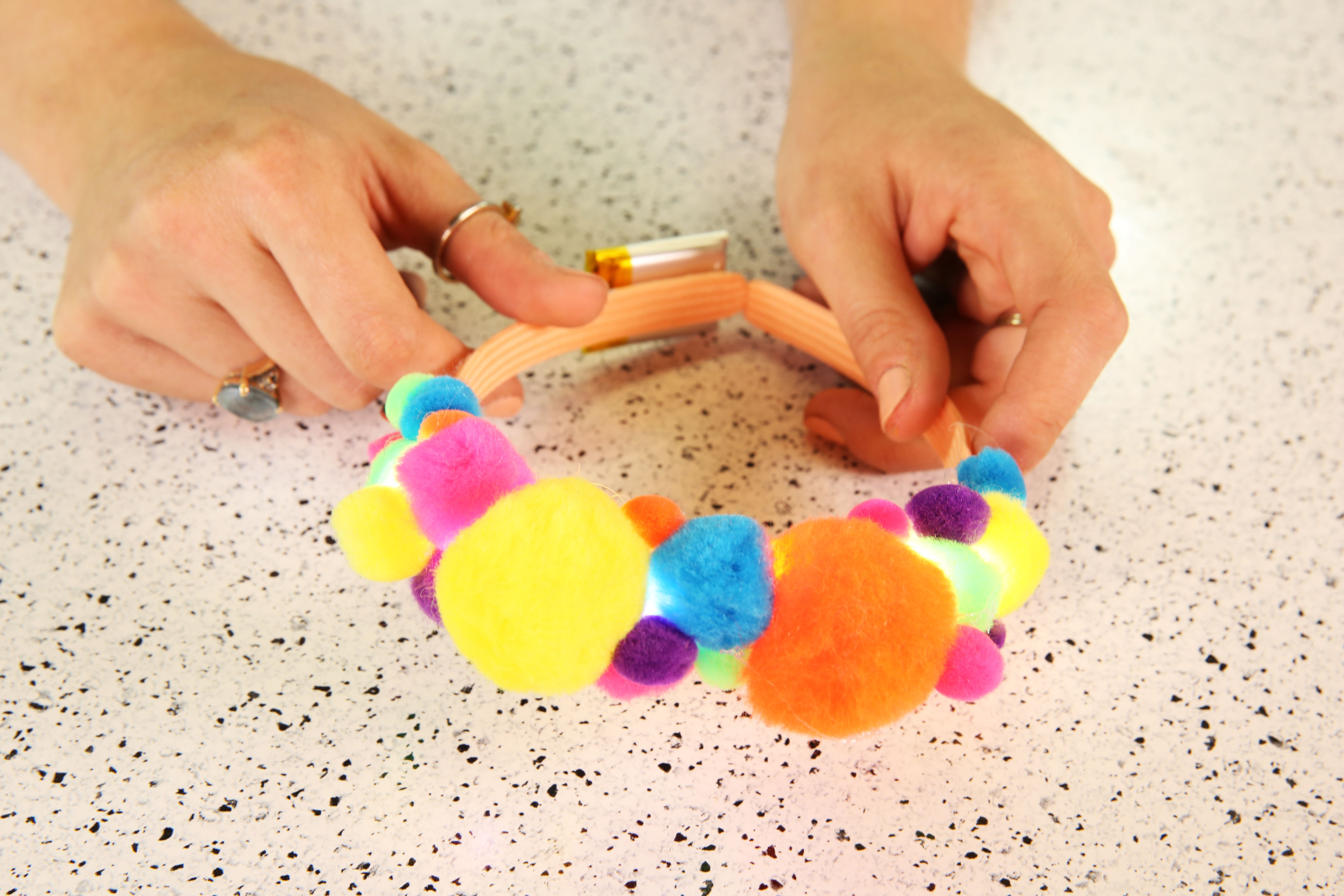
Hot glue your PomPoms on top of the LEDs. Through experimentation, I found that it looked better by adding the larger PomPoms at the crown of the headband and tapered the size down as I moved to the sides.

STEP 9:
Add double stick tape on one side of your battery to the bottom of the headband on the same side as the connector. Wrap the wires around the headband to secure and add a drop of glue to secure the wires. Make sure to leave some extra wire so that you can unplug the JST connector.
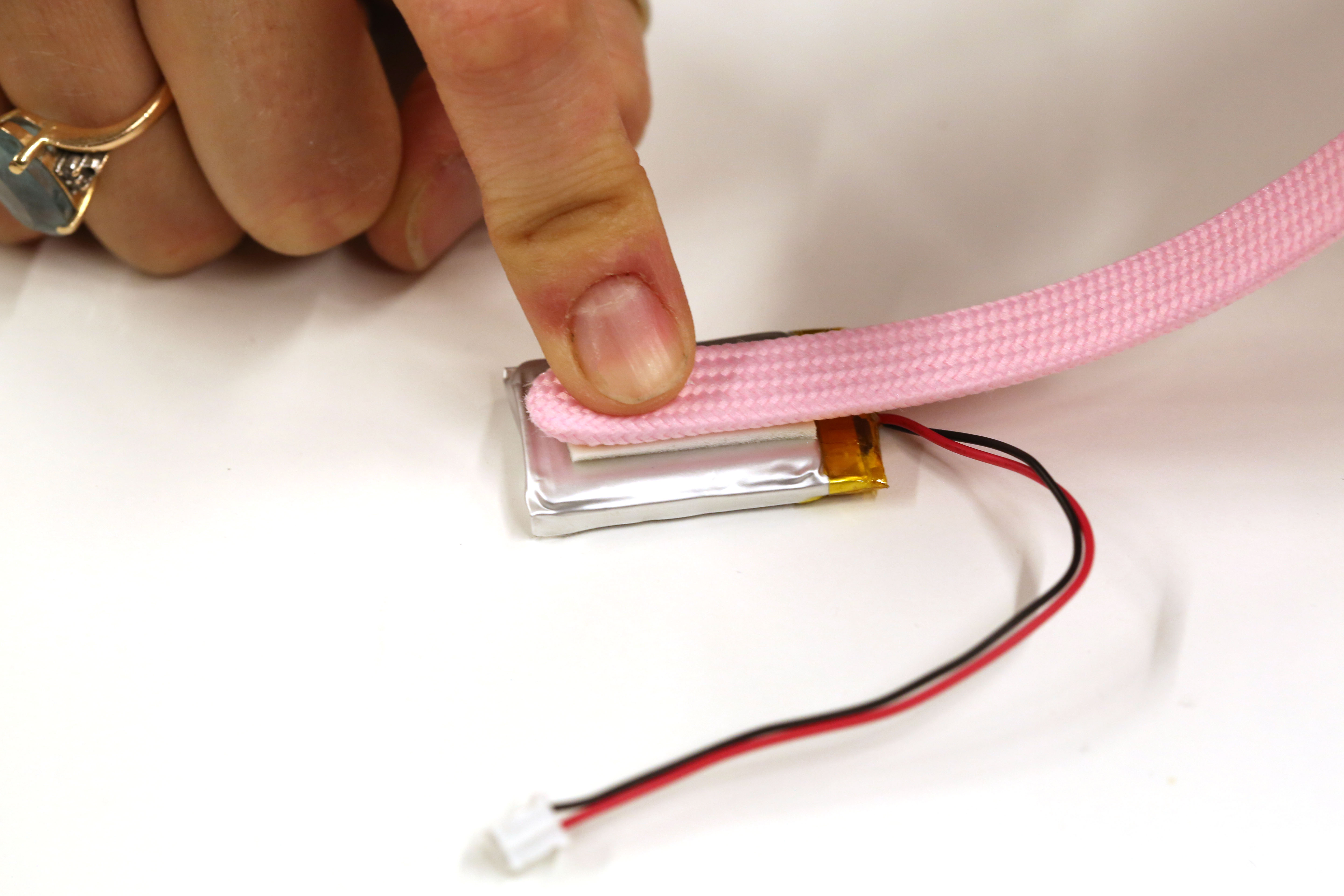
*PLEASE NOTE: It is never a good idea to apply heat to a LiPo battery using a hot glue gun. A safer solution is to secure the battery with some thread or tape.
STEP 10:
Plug in the battery, and enjoy!
Advanced PomPom Headband
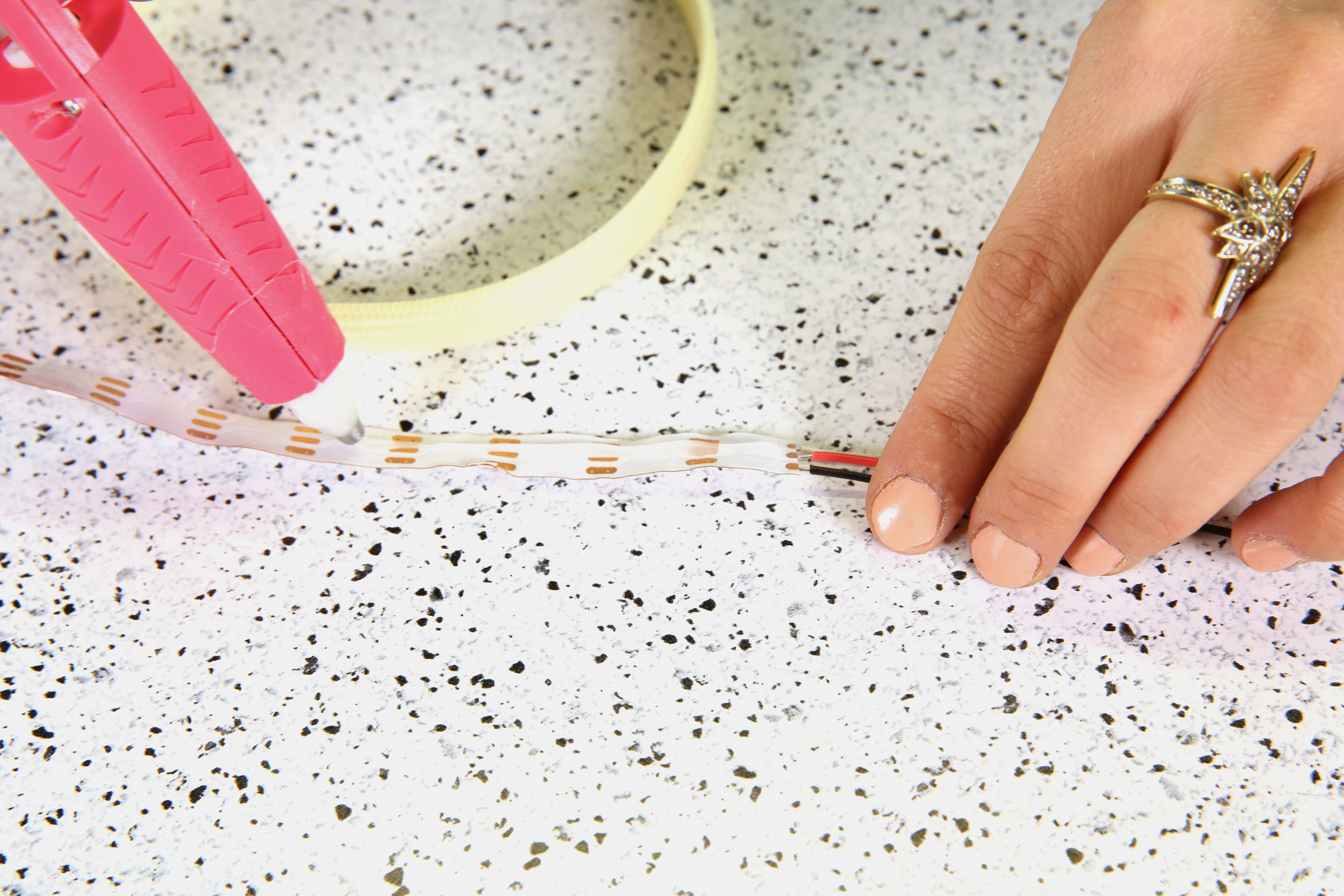
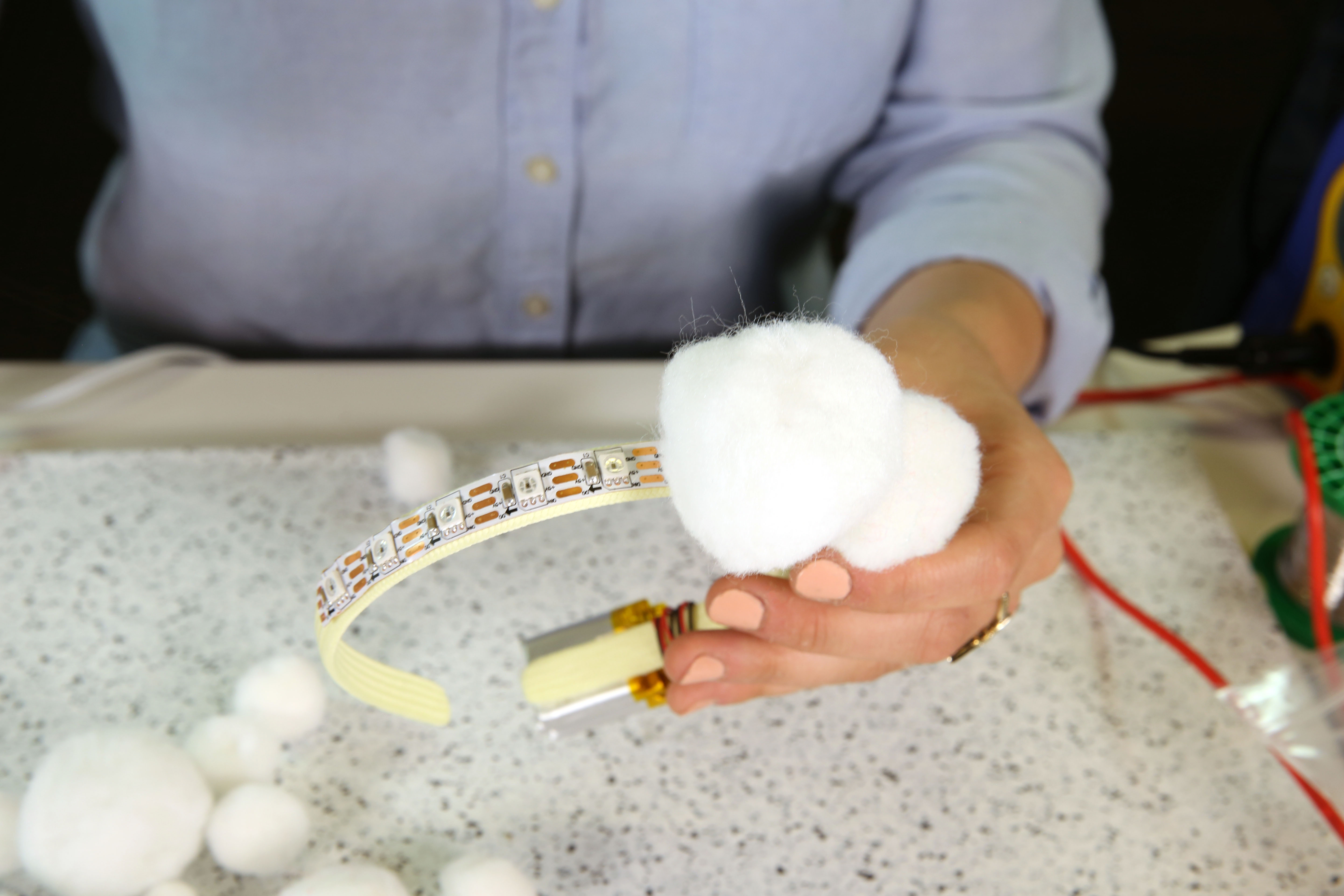
STEP 1:
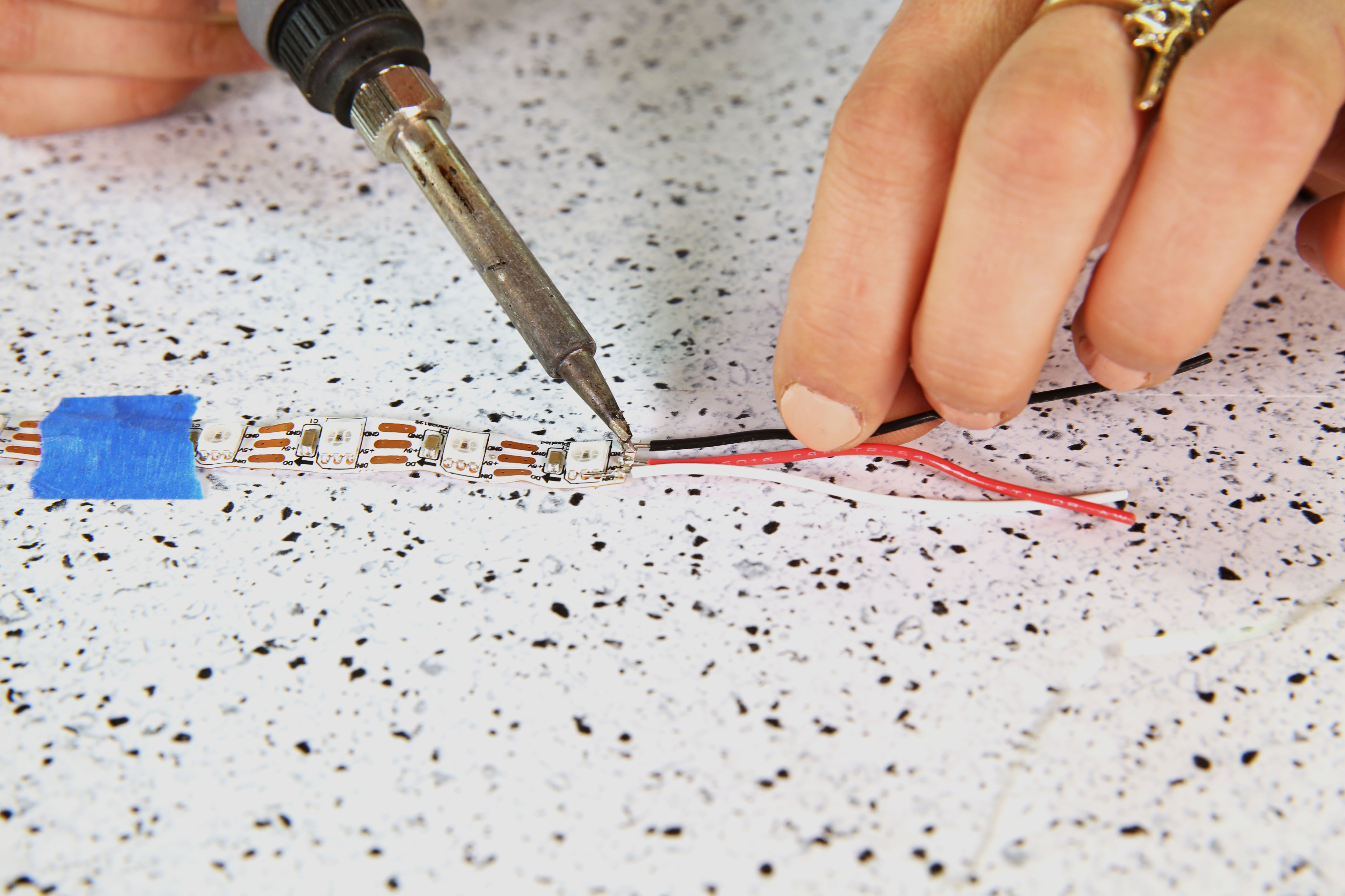
Cut your addressable LED strip down so that you have 10x LEDs on one strip. Cut three strands of hookup wire and strip them using a wire stripper. Solder the hook up wire leads to the solder pads on the LED strip. Feel free to use some tape to help hold down the LED strip when soldering the wires. Make sure you are on the end that says DIN and not DOUT. We will be using these leads again in step 7.
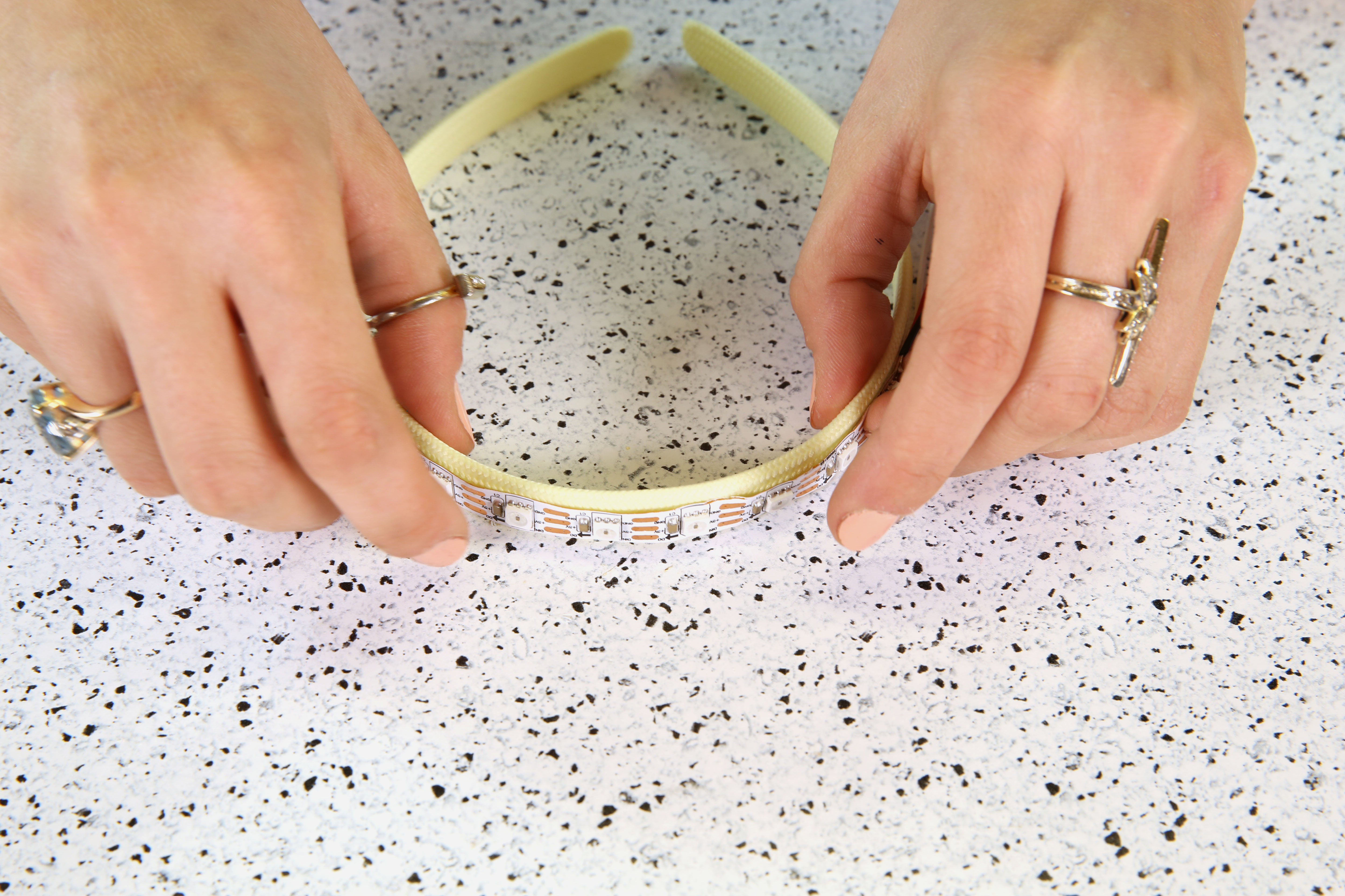
STEP 2:
Add hot glue to the back of the LED strip.
Attach the LED strip to the top of the headband before the hot glue cools down and make sure to center it as much as possible. Set aside when complete.
STEP 3:
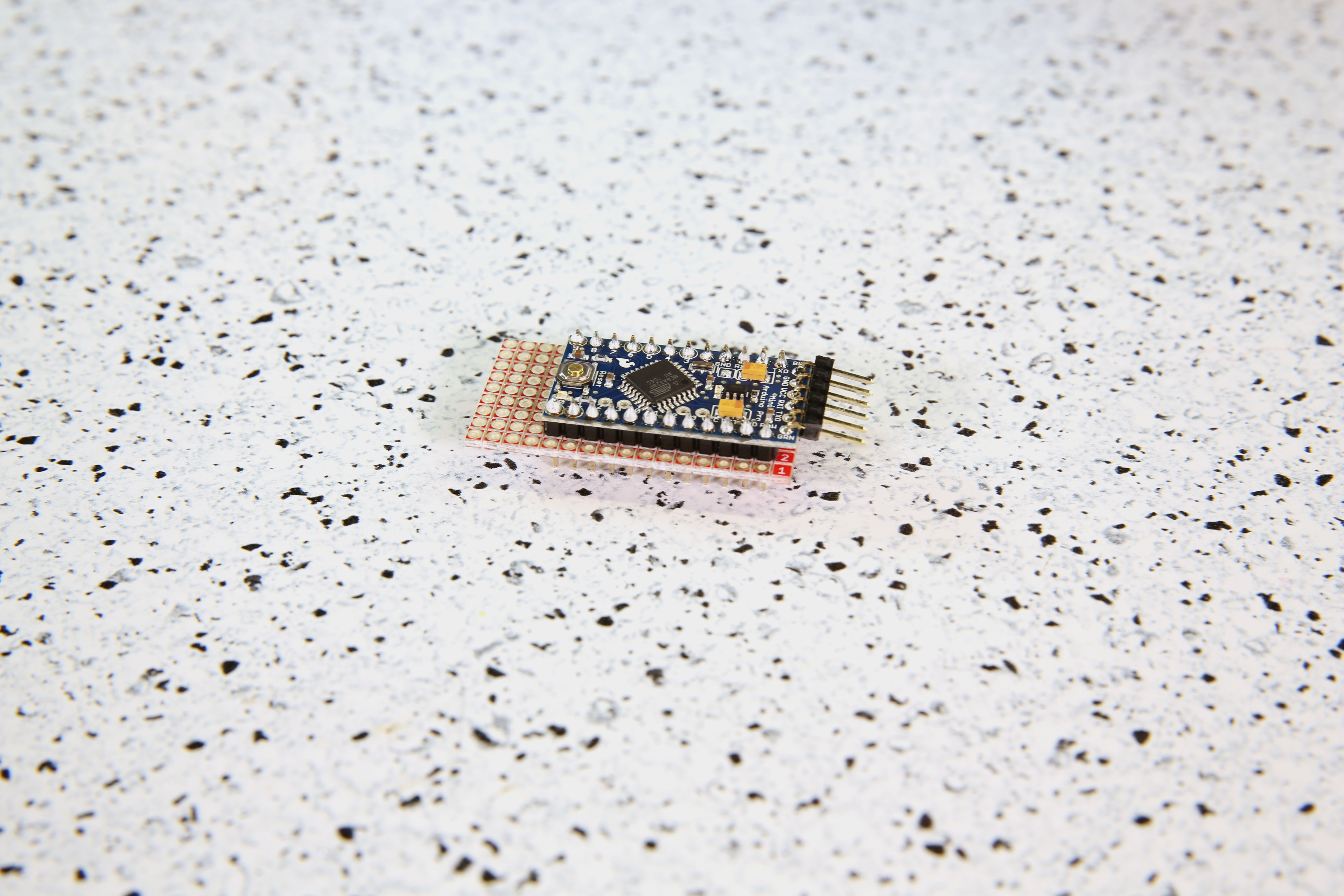
Prepare your Arduino Pro Mini by soldering headers to the plated through holes. Solder right angle headers to the FTDI headers at the top of the board (short side), and straight headers to plated through holes on the sides of the board (longer side).

STEP 4:
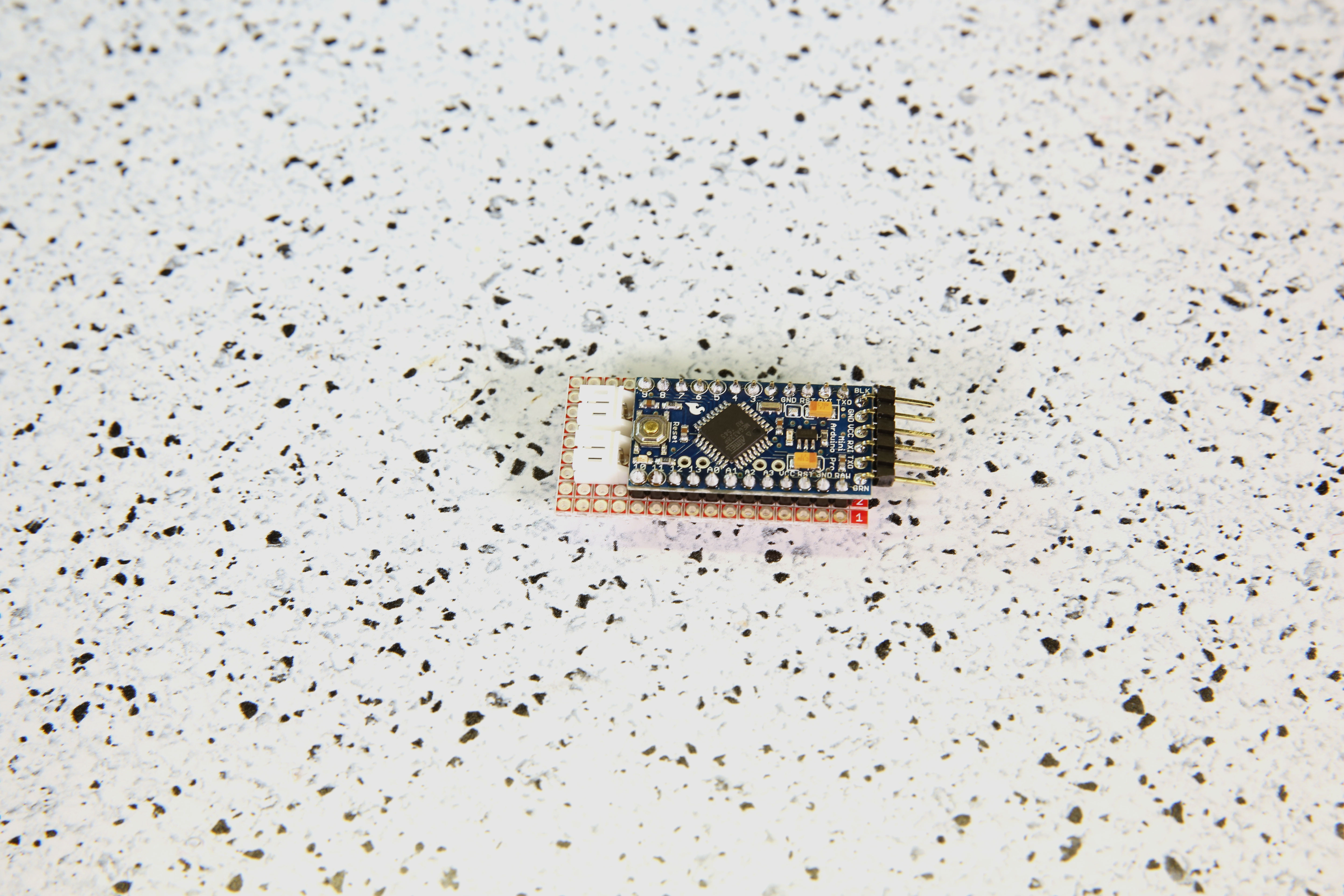
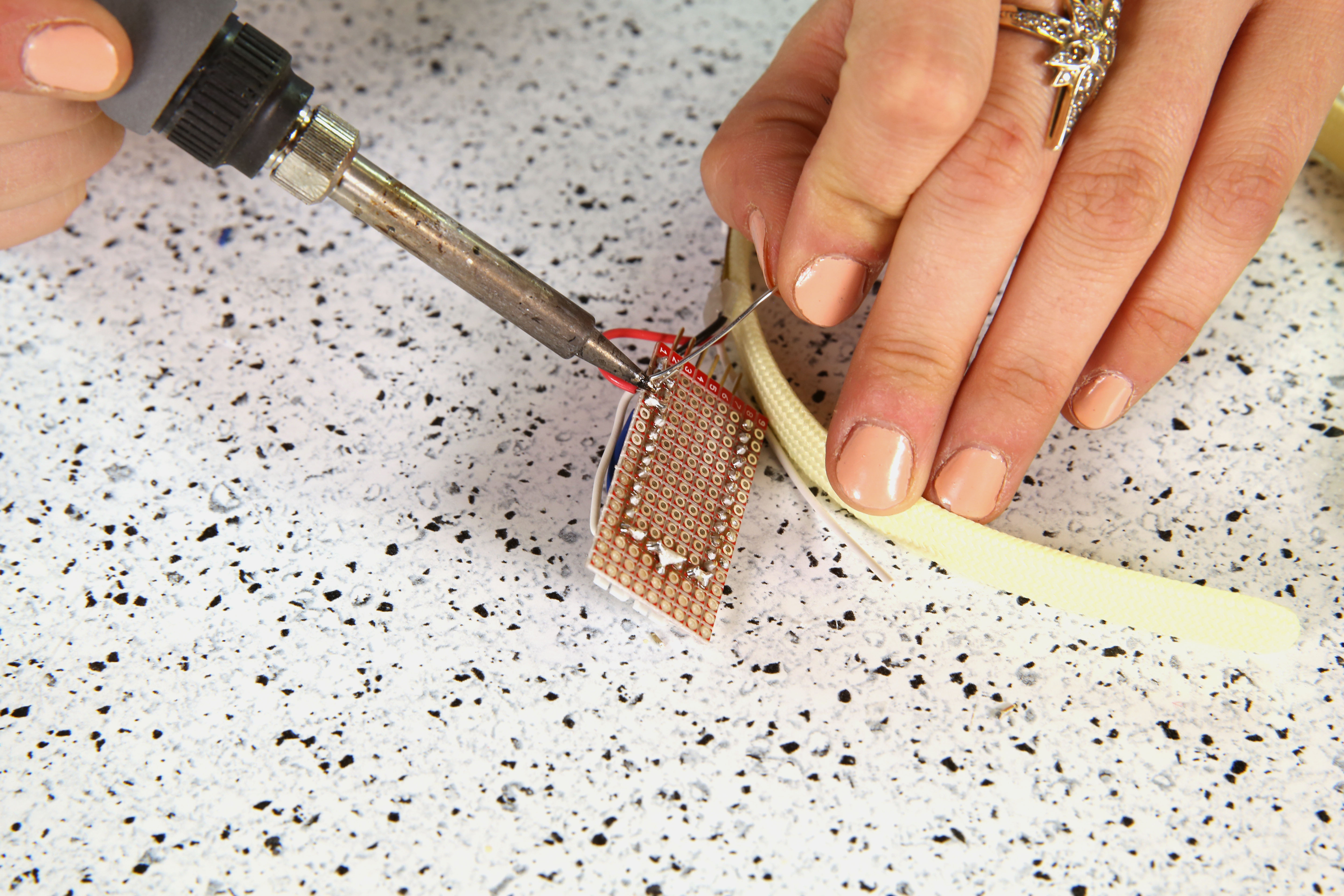
Break off a grid of 9x16 from the snappable protoboard. Solder your Arduino to it. Ensure that it is positioned so that there is one row of protoboard available on each side, and space for the programming headers.
STEP 5:
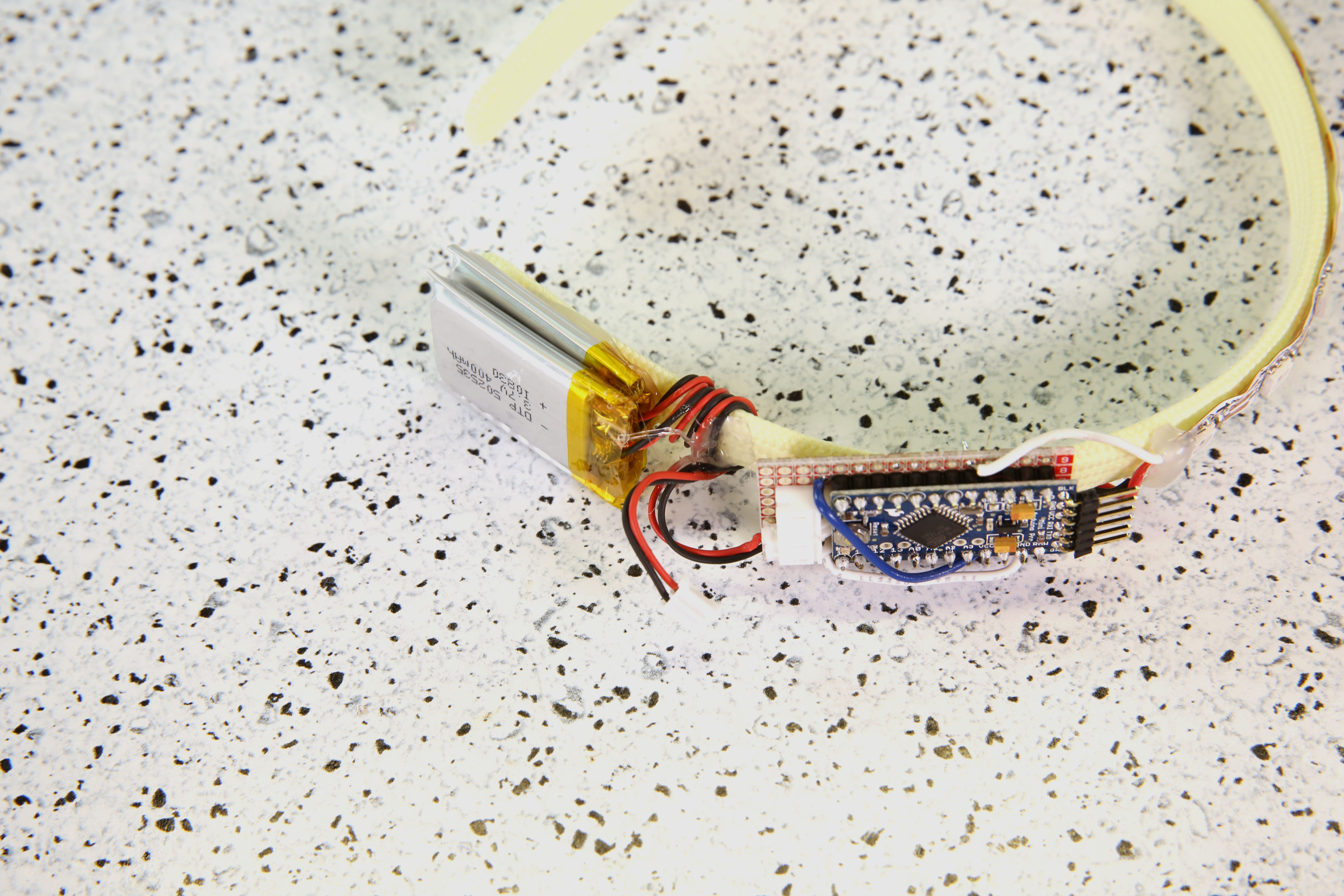
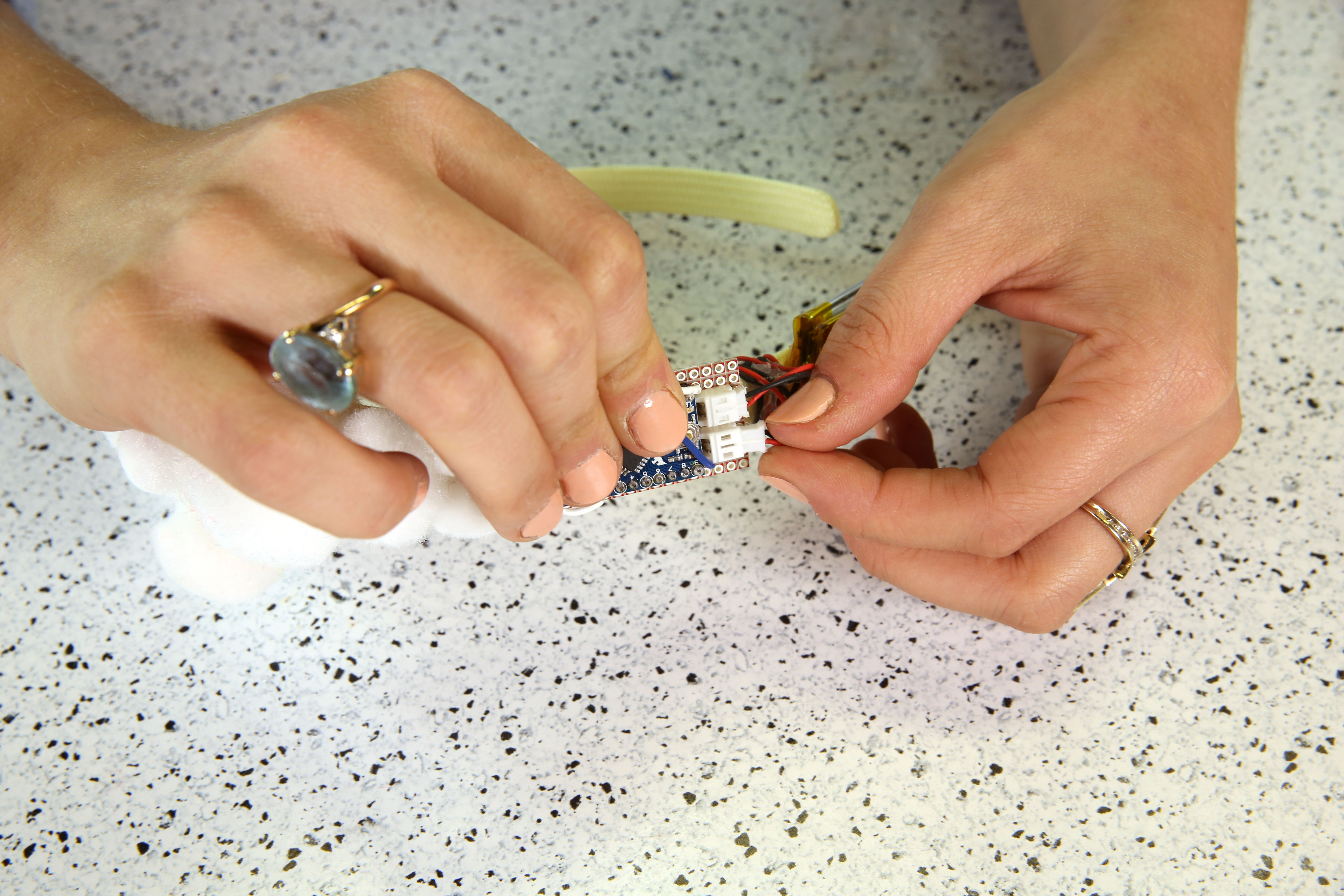
Add 2x JST connectors wired parallel using hook up wire. This means that you will need to connect the Arduino's Vcc pin to the red wire of BOTH batteries and the GND pin to the black wires of BOTH batteries. As a result, you will have a capacity of 800mAh for your power source. If you have an 800mAH battery or above, you only need one JST connector.
*PLEASE NOTE: In order to connect two batteries in parallel, they MUST be the same voltage. While not reflected in these images, you can also add a Schottky diode in series for each LiPo battery for extra protection.
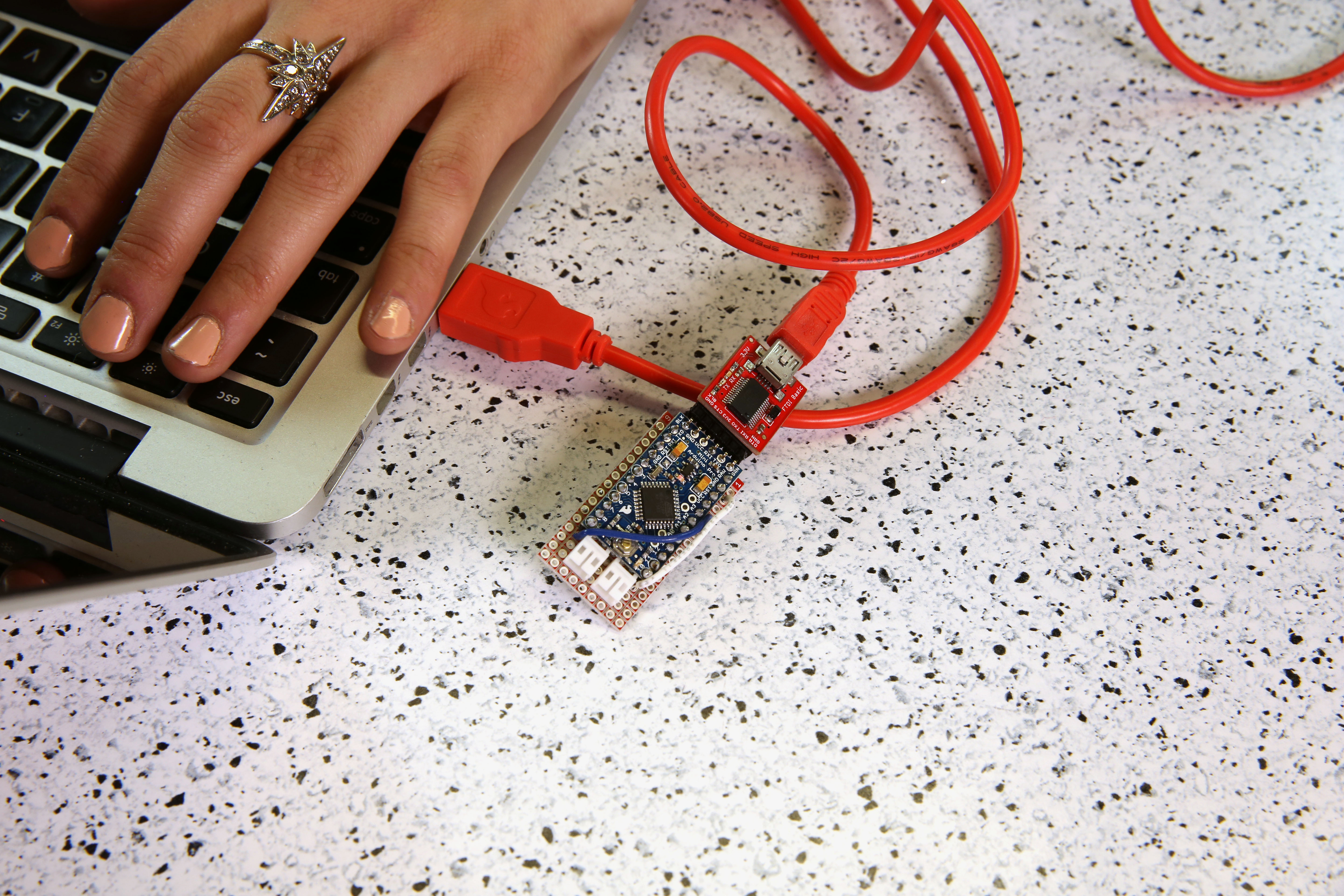
Step 6:
Before programming your Arduino, make sure to connect the 5V Arduino Pro Mini, 5V FTDI, and USB cable to your computer.
In order for this example code to work, you will need to install the Adafruit Neopixel Library. For Arduino IDE users, click here to download a copy of the NeoPixel library along with some example code SparkFun has created.
If you are unfamiliar with uploading a program to your Arduino or the library installation process, please visit this tutorial on installing and using the Arduino IDE, and this tutorial on installing Arduino Libraries.
Program your Arduino by uploading the example code provided below.
language:c
//PomPom headband by Melissa Felderman for SparkFun
//This sketch is an edited version of the Adafruit Neopixel Strand Test example code from the Neopixel Library.

#include <Adafruit_NeoPixel.h>
#ifdef __AVR__
  #include <avr/power.h>
#endif

#define PIN 2


Adafruit_NeoPixel strip = Adafruit_NeoPixel(10, PIN, NEO_GRB + NEO_KHZ800);


void setup() {
  // This is for Trinket 5V 16MHz, you can remove these three lines if you are not using a Trinket
  #if defined (__AVR_ATtiny85__)
    if (F_CPU == 16000000) clock_prescale_set(clock_div_1);
  #endif
  // End of trinket special code


  strip.begin();
  strip.show(); // Initialize all pixels to 'off'
}

void loop() {

  rainbowCycle(20);

}


// Slightly different, this makes the rainbow equally distributed throughout
void rainbowCycle(uint8_t wait) {
  uint16_t i, j;

  for(j=0; j<256*5; j++) { // 5 cycles of all colors on wheel
    for(i=0; i< strip.numPixels(); i++) {
      strip.setPixelColor(i, Wheel(((i * 256 / strip.numPixels()) + j) & 255));
    }
    strip.show();
    delay(wait);
  }
}


// Input a value 0 to 255 to get a color value.
// The colours are a transition r - g - b - back to r.
uint32_t Wheel(byte WheelPos) {
  WheelPos = 255 - WheelPos;
  if(WheelPos < 85) {
    return strip.Color(255 - WheelPos * 3, 0, WheelPos * 3);
  }
  if(WheelPos < 170) {
    WheelPos -= 85;
    return strip.Color(0, WheelPos * 3, 255 - WheelPos * 3);
  }
  WheelPos -= 170;
  return strip.Color(WheelPos * 3, 255 - WheelPos * 3, 0);
}
STEP 7:
Find the hook up wire leads we attached to the LED strip in Step 1. Solder the DIN lead from the LED strip to pin 2 on your Arduino, GND to GND, and VCC to VCC. Since the snappable protoboards do not have metal traces connecting the pins together, you will need to add a solder bridge (similar to this example) between the holes to complete each connection.
STEP 8:
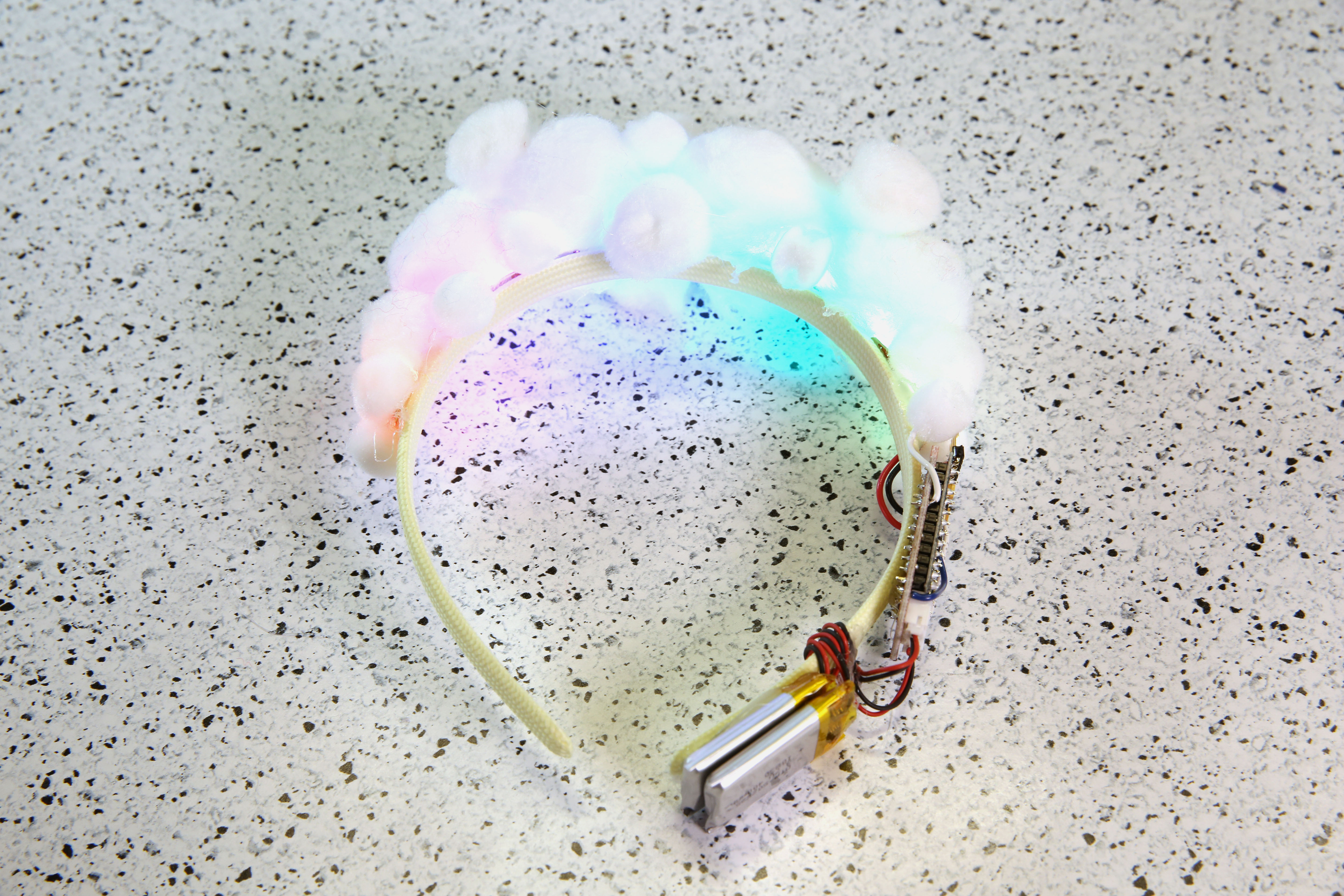
Test your circuit! Make sure that your circuit is working properly and lighting up before moving on to the next step. To test, plug in the LiPo battery into the circuit. If you used the provided code, your LEDs should animate with a rainbow spectrum that slowly flows from color to color.
STEP 9:
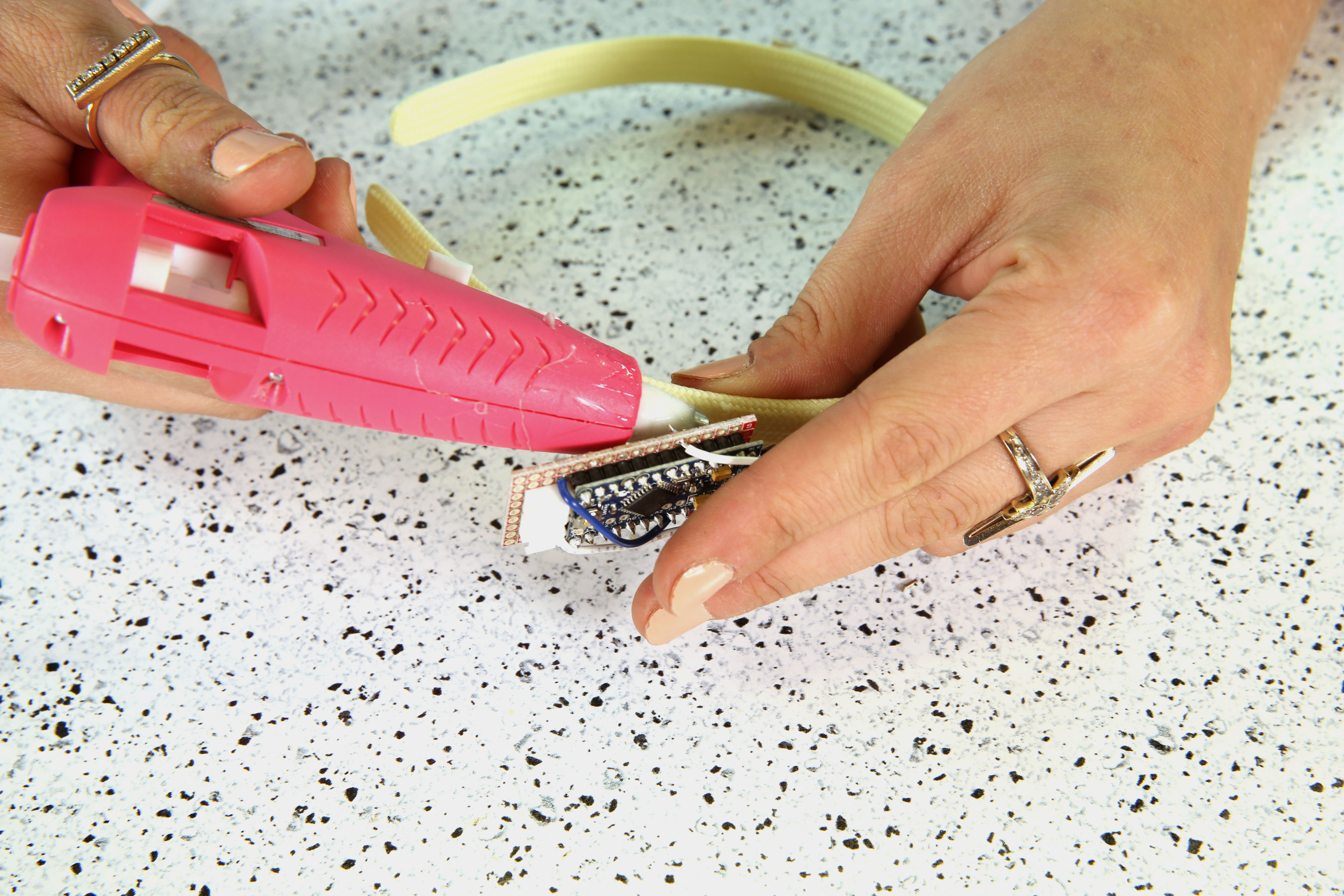
Glue down the back of the circuit to your headband as shown in the image below.
STEP 10:
On the same side, add double stick tape to your battery on the very bottom and attach to the headband. Wrap the wires around the headband to secure the wires. Add an additional drop of glue to hold the wires down against the headband.
*PLEASE NOTE: It is never a good idea to apply heat to a LiPo battery using a hot glue gun. A safer solution is to secure the battery with some thread or tape.
STEP 11:
Glue white PomPoms directly on top of the area covered by the LED strip.
STEP 12:
Plug in and enjoy!
Resources and Going Further
Looking for another project? Check out these similar projects for inspiration!