LiPo Fuel Gauge (MAX1704X) Hookup Guide
 bboyho
Breakout Board (MAX17043) Hardware Overview
In this section, we will highlight parts of the LiPo Fuel Gauge (MAX17043) breakout board. For users that have a built in fuel gauge (MAX17043/MAX17048) already on your Arduino microcontroller, you can skip this section. The row of 1x3 header pins are arranged in a way so that you can insert the board a standard breadboard.
 |
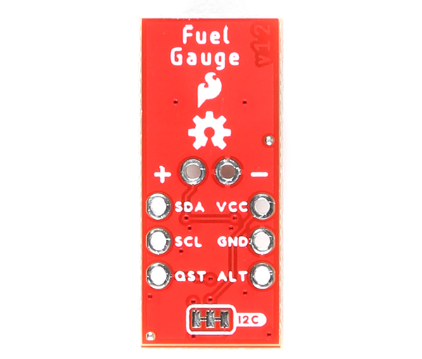 |
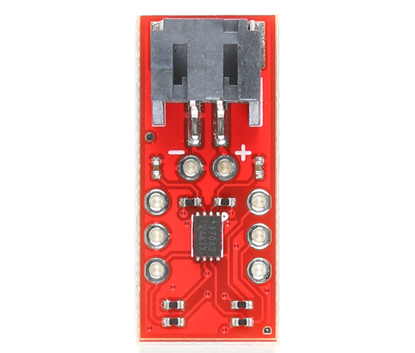
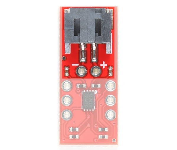
| Top View | Bottom View |
Battery and Power Input
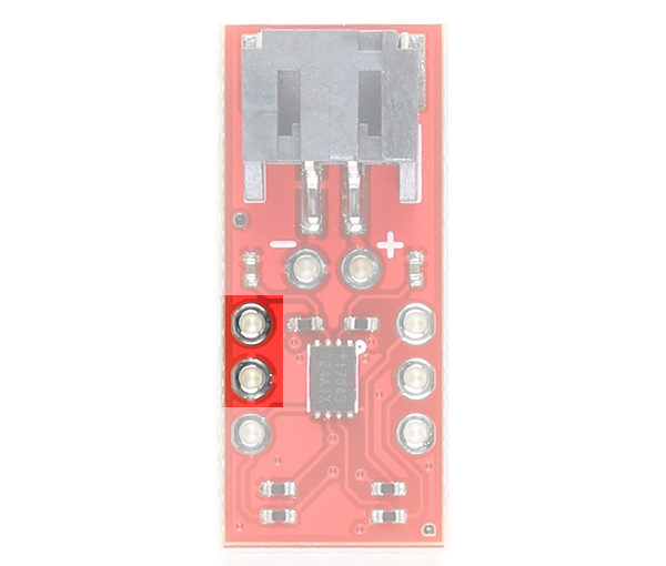
The board includes a 2-pin JST connector to mate with single cell LiPo batteries. We have also broke out the pins to PTHs labeled as + and −. These can be used to solder the LiPo battery wires directly to the board and to your system's VBATT pin. The input voltage range is between 2.5V to 4.5V. Note that the nominal voltage of a single cell LiPo Battery is around 3.7V. Fully charged, the voltage is at around 4.2V. This input also powers the IC and should be connected to your system's power input as well.
 |
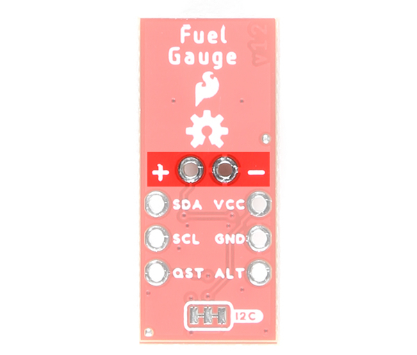 |
| Battery Input Highlighted - Top View |
Battery Input Highlighted - Bottom View |
Pull-Up Resistor's Voltage Input
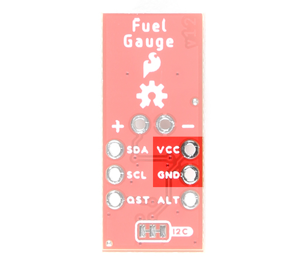
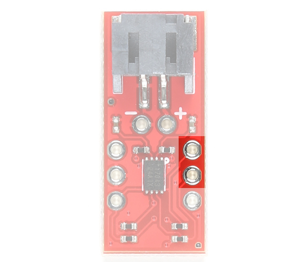
VCC pin is connected to the I2C and alert pull-up resistors. This voltage input pin is different from the battery input pin. The maximum voltage that can be connected to this pin is 5.5V. This is typically 3.3V. If you decide to daisy chain the LiPo Fuel Gauge to Qwiic-enabled devices, we recommend using 3.3V.
 |
 |
| Power Input Highlighted - Top View |
Power Input Highlighted - Bottom View |
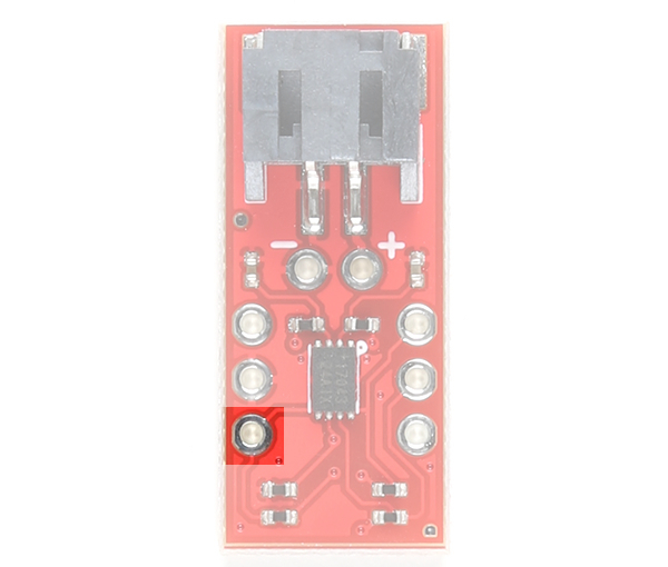
I2C Pins
The I2C pins are broken out to PTHs. The 7-bit, unshifted address of the MAX17043 is 0x36. The address becomes 0x6C for write and 0x6D for read. There are two 2.2kΩ pull-up resistors connected to the SDA and SCL lines. These lines are connected to the VCC pin.
 |
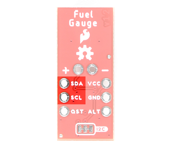 |
| I2C Pins Highlighted - Top View |
I2C Pins Highlighted - Bottom View |
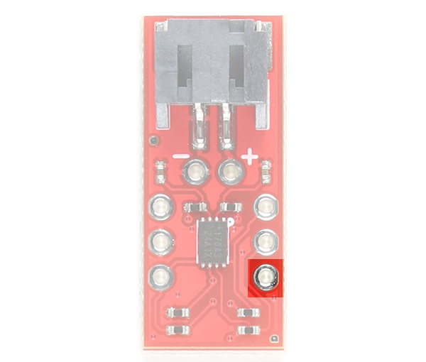
Alert Pin (ALT)
The ALT pin is the alert pin. The datasheet labels this as ALRT but we decided to label it as ALT due to the size of the board. This pin is active low indicating that there is a low state of charge. This pin can be connected to a microcontroller's interrupt pin. This pin can be left unconnected and the status can be viewed though I2C.
 |
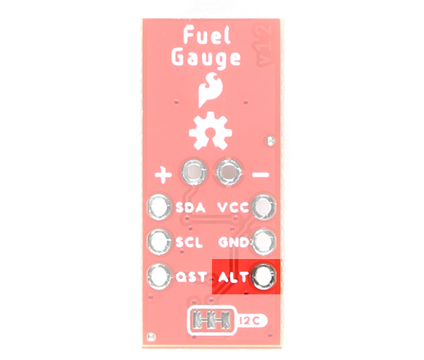 |
| Alert Pin Highlighted - Top View |
Alert Pin Highlighted - Bottom View |
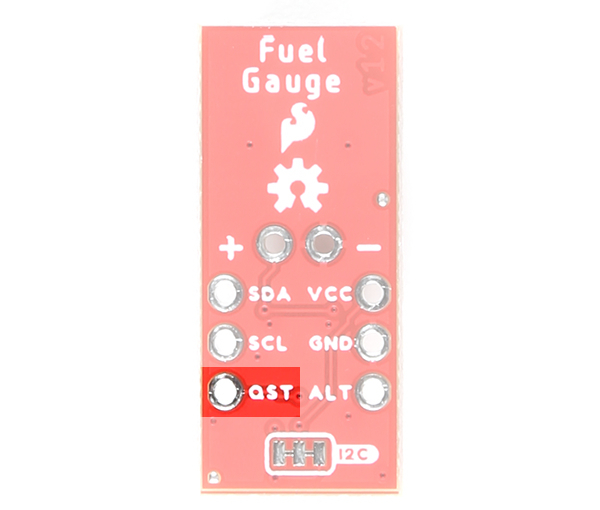
Quick-Start Input Pin (QST)
The QST pin is for quick-start input. The datasheet labels this pin as QSTRT but we decided to label it as QST due to the size of the board. This allows users to reset the device through hardware. By default, the pin is connected to ground through a built-in 2.2kΩ resistor as suggested by the datasheet. A rising edge on this pin will initiate a hardware reset. One possible application is connecting this pin to a microcontrollers reset pin should users decide to initiate a hardware reset. A reset can also be initiated through software as well.
 |
 |
| Quick-Start Input Pin Highlighted - Top View |
Quick-Start Input Pin Highlighted - Bottom View |
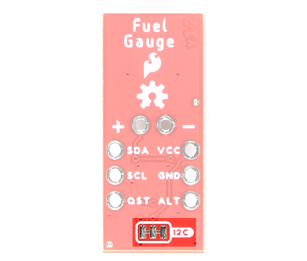
Jumpers
By default, this 3-pad jumper is closed and located on the bottom of the board. The 2.2kΩ pull-up resistors are attached to the primary I2C bus; if multiple devices are connected to the bus with the pull-up resistors enabled, the parallel equivalent resistance will create too strong of a pull-up for the bus to operate correctly. As a general rule of thumb, disable all but one pair of pull-up resistors if multiple devices are connected to the bus.
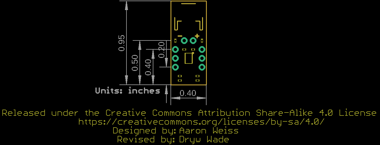
Board Dimensions
The board is 0.40" x 0.95". To make the board as small as possible, there are no mounting holes included on the board.