LiPo Fuel Gauge (MAX1704X) Hookup Guide
 bboyho
Hardware Hookup
Now that we're familiar with the LiPo Fuel Gauge Breakout, let's connect it to a microcontroller and monitor a single cell LiPo battery!
LiPo Fuel Gauge Breakout Connections
For a permanent connection, we recommend soldering wires (or headers) to the PTHs on the breakout. We chose to use a combination of header pins and wires when prototyping. Of course, you could also solder wires to the breakout board as well. For a temporary connection during prototyping, you can use IC hooks like these.
How to Solder: Through-Hole Soldering
Working with Wire
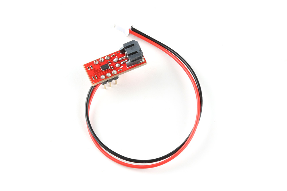
We recommend soldering the header pins and wires on one side. After soldering two rows of 1x3 header pins and a two wire cable, your setup should look like the following image below. We decided to solder the straight header pins and wire all on the top side of the board. Depending on your application, you could solder the straight header pins on the bottom side as well. This will allow you to easily view the silkscreen if you decide to solder on the bottom. Make sure to wire the red wire to the PTH labeled as "+" and the black wire to the PTH labeled as "−".
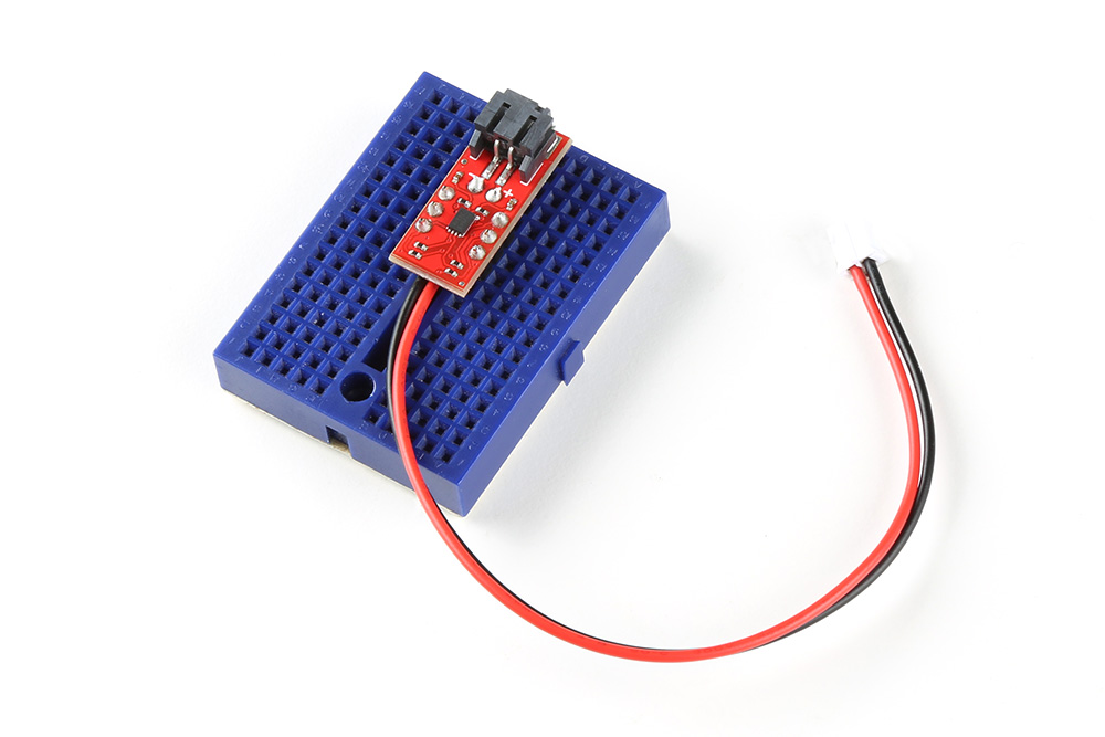
For users that want to prototype on a breadboard, you could insert the breakout board in the middle of a breadboard. Thanks to the header pin's plastic spacers, the cable can fit between the PCB and the breadboard. The image below shows the breakout board inserted into a mini breadboard. The edge of the board is on the edge of the mini breadboard so that you can disconnect/connect a LiPo battery to the 2-pin JST connector.
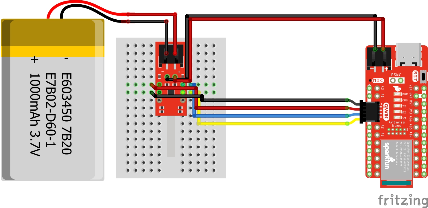
Connecting the LiPo Fuel Gauge to a Microcontroller
Connect the I2C pins, GND, and Vcc from LiPo Fuel Gauge to your microcontroller. We recommend using 3.3V for Vcc. Insert the battery into the LiPo Fuel Gauge's 2-pin JST connector. Then connect the JST cable that was soldered to your microcontroller's voltage input. In this case, we connected Qwiic cable to the RedBoard Artemis Nano's Qwiic connector and the 2-wire JST cable to the 2-pin JST connector.
Connecting a LiPo Charge Circuit
Users can include a LiPo charge circuit to safely charge the LiPo battery without needing to remove the LiPo battery from the LiPo Fuel Gauge. Below is one example that uses the LiPo Charger Plus to charge a single cell LiPo battery while it is also connected to an Arduino Pro Mini 3.3V/8MHz.

As the note indicates in the image, make sure to choose one power source for your Arduino microcontroller to avoid conflicting voltages: either from the LiPo battery or a USB-to-serial converter.
The Fritzing diagram shows male header pins connected to all but the VCC pin on the serial header. When connecting the USB-to-serial converter, this allows users to upload code or view serial data through the Arduino Serial Monitor without needing to worry about conflicting voltages from the FTDI's 3.3V pin.
Connecting a Boost Circuit
Users can also include a boost circuit when users need a steady 5V input. Below is one example that uses the LiPo Charger/Booster 5V/1A to boost the voltage to 5V for the RedBoard Qwiic. Most microcontrollers usually run at 3.3V so you may not need to worry about boosting it for your Arduino. However, 5V could be used for addressable LEDs, servos, and motors.
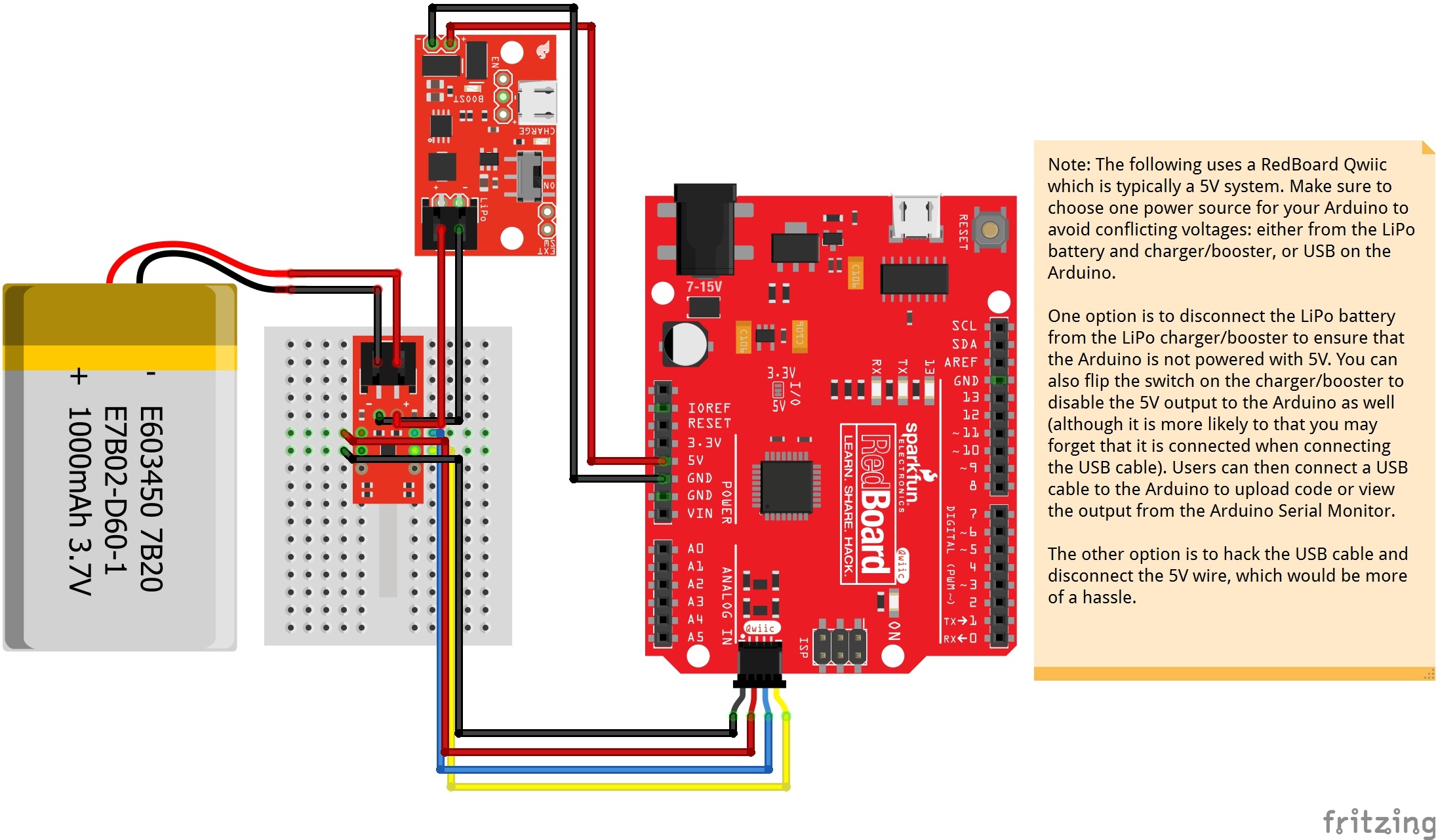
As the note indicates in the image, make sure to choose one power source for your Arduino microcontroller to avoid conflicting voltages: either from the LiPo battery and charger/booster, or USB on the Arduino.
The Fritzing diagram does not show the wires disconnected from the LiPo charger/booster. However, this would be the better option to ensure that the battery is not connected to the RedBoard Qwiic's input power pins. Users could also disconnect the 5V pin from the RedBoard Qwiic's input power pin.
The other option would be to hack the USB cable and disconnect the 5V wire, which would be more of a hassle.
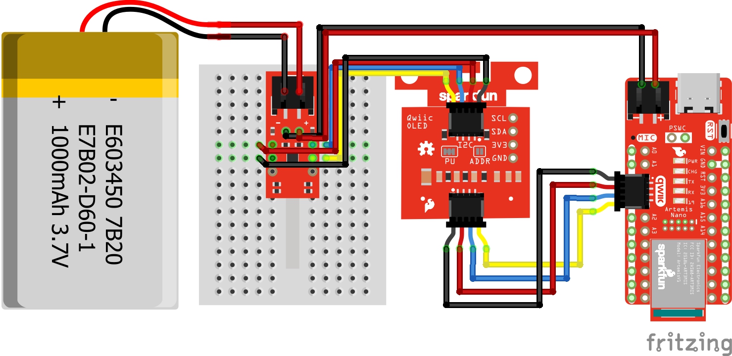
Connecting a Display
For users that are interested in viewing how much charge a single cell LiPo battery has a available without a computer, users can attach a display to your microcontroller. Below is one example that addes a Qwiic Micro OLED to the first setup. Since you can control the display through I2C, it can be daisy chained using the Qwiic connectors. If you decide to use a different display, you will need to write code to output the values on the display.