IoT RedBoard ESP32 Development Board Hookup Guide
 SparkFro
Hardware Overview
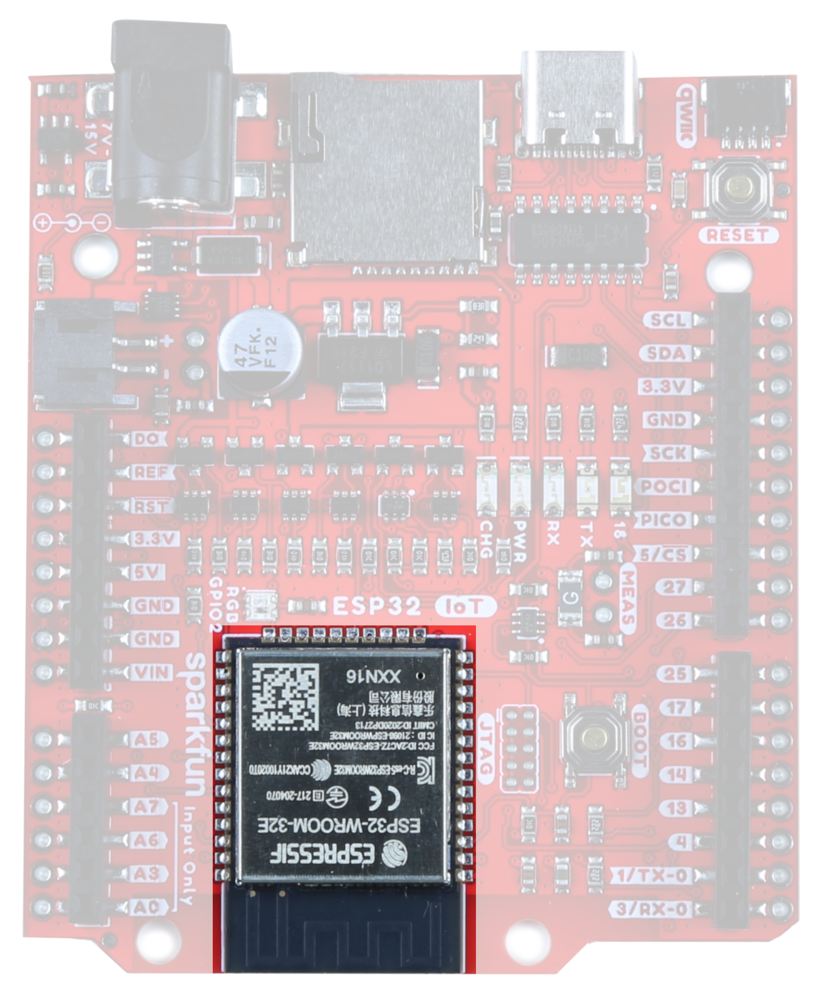
ESP32
At the core of the module is the ESP32-D0WD-V3 chip. The embedded chip is designed to be scalable and adaptive. There are two CPU cores that can be individually controlled, and the CPU clock frequency is adjustable from 80 MHz to 240 MHz. The chip also has a low-power coprocessor that can be used instead of the CPU to save power while performing tasks that do not require much computing power, such as monitoring of peripherals. ESP32 integrates a rich set of peripherals, including capacitive touch sensors, SD card interface, Ethernet, high-speed SPI, UART, I2S and I2C. Check out the datasheet for more info.
Power
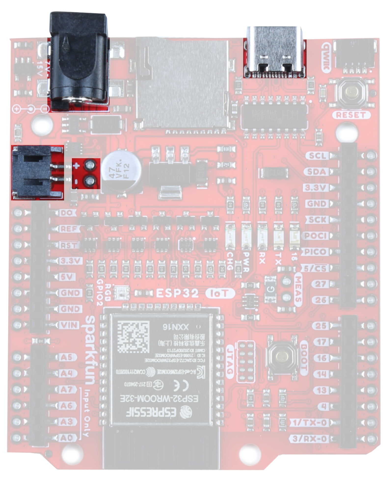
There are a number of different ways to power the SparkFun ESP32 IoT Dev Board:
- USB-C
- barrel jack connector
- LiPo battery charge circuit and fuel gauge.
- power pins broken out on the edge of the board
The easiest way (which will also allow you to program your board) is to simply plug it into your computer via USB-C. If you choose to power it via USB, the other end of the USB cable can be connected to either a computer or a 5V (regulated) USB wall charger. Otherwise, should you choose to use the barrel jack, any wall adapter connected to this jack should supply a DC voltage between 7 and 15V. You could also power the board via the header pins. Note that the GPIO pins are NOT 5V tolerant! Make sure that your voltage is regulated when applying power to the 5V or 3.3V pins, respectively.
Charge Circuit
For those using a LiPo battery, note that there is a LiPo charging circuit on the board! By default, RPROG=2k and ICHG=500mA. To calculate the charge current, use the following equation:

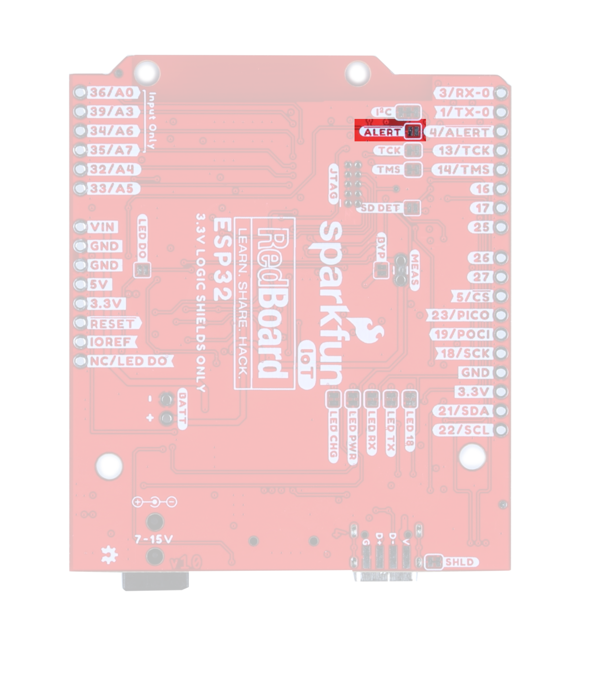
ALERT Jumper
If you are powering your board with a LiPo battery, closing this jumper will enable the Battery Fuel Gauge Alert to be connected to GPIO pin 4. The I2C address to access the battery fuel gauge is 0x36.
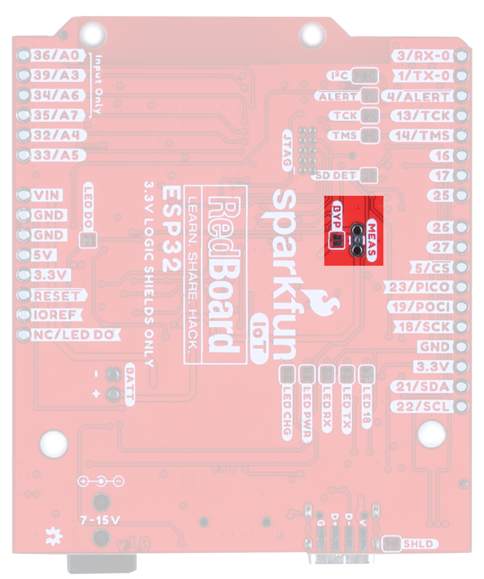
Current Measurement & BYP Jumper
To enable measurements and determine how long your battery might last, we've added a NC (normally closed) jumper between the two MEAS PTH pins. By cutting this jumper, the VDD trace to the module is interrupted. Soldering in a male jumper or wires into the accompanying holes will give you the ability to insert a current meter and precisely monitor how much current your application is consuming.
Note that we have also added a PTC fuse bypass jumper - this fuse will trip around 1.5A to protect anything from frying; if you really need more current, close the BYP jumper to bypass the fuse.
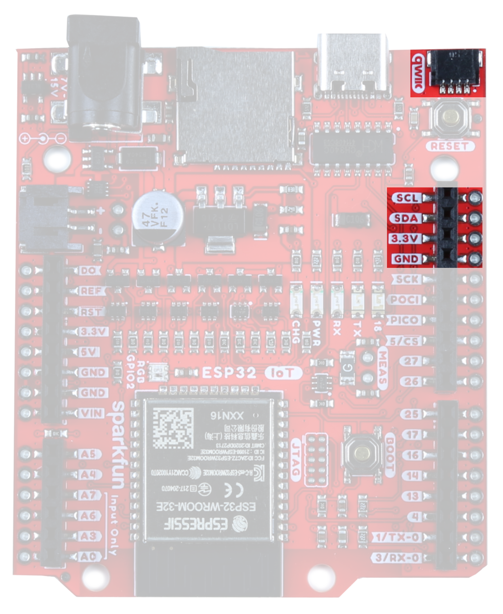
Qwiic Functionality
Our Qwiic Ecosystem makes sensors pretty much plug and play. The Qwiic connector provides power and I2C connectivity simultaneously. In addition, we've broken out the I2C functionality to PTH.
In addition, The IoT RedBoard ESP32 Development Board comes equipped with pull-up resistors on the clock and data pins. If you are daisy-chaining multiple Qwiic devices, you will want to cut this jumper; if multiple sensors are connected to the bus with the pull-up resistors enabled, the parallel equivalent resistance will create too strong of a pull-up for the bus to operate correctly. As a general rule of thumb, disable all but one pair of pull-up resistors if multiple devices are connected to the bus. To disable the pull up resistors, use an X-acto knife to cut the joint between the two jumper pads highlighted here.
 |
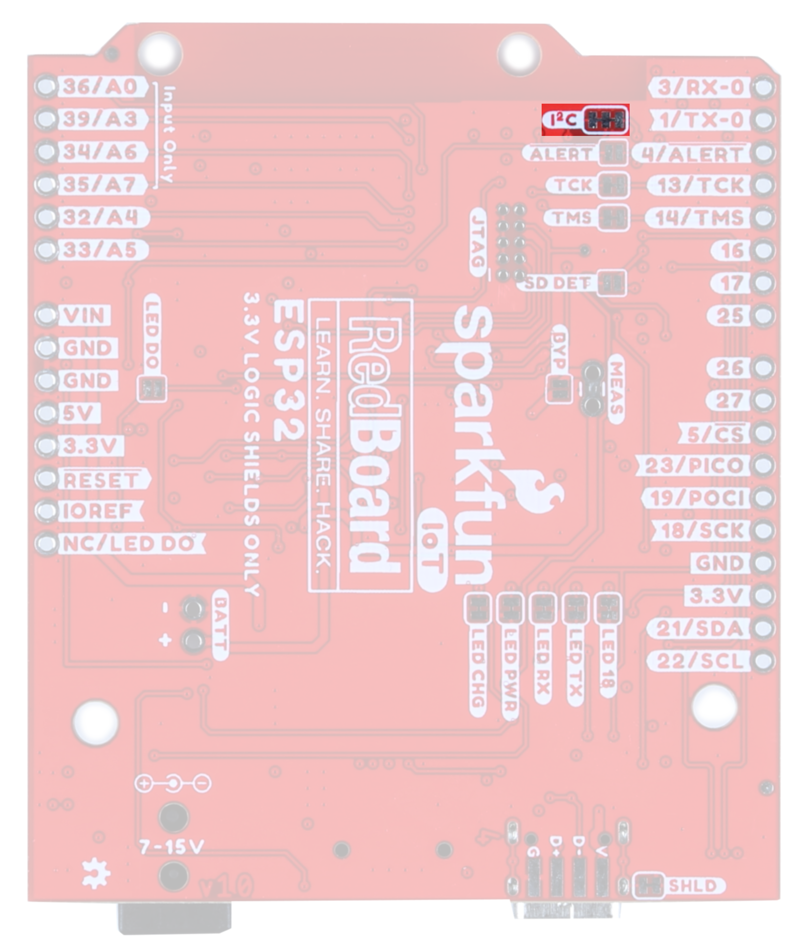 |
| I2C Pins and Qwiic Connector | I2C Jumper |
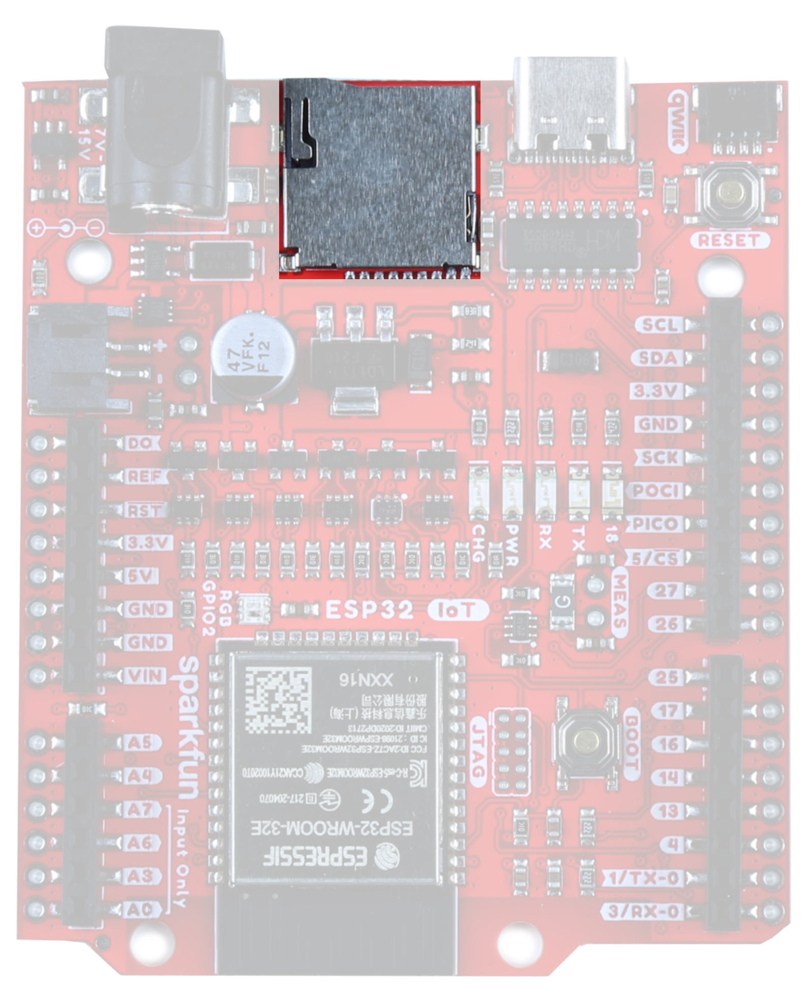
MicroSD
The board includes a microSD socket if your application requires you to log and save data to a memory card.
The SD card socket is able to detect whether or not an SD card has been inserted. By default, this jumper is open, but should you wish to use this functionality, close this jumper and pull the pin high. When an SD card is inserted, the pin will be pulled low and an interrupt can be triggered to notify the user.
 |
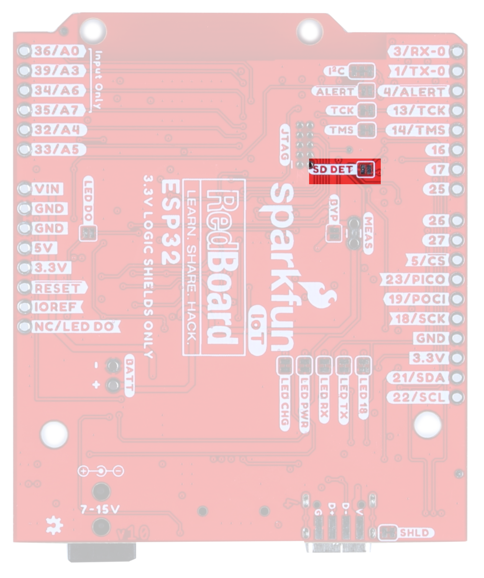 |
| MicroSD card slot | SDDET Jumper |
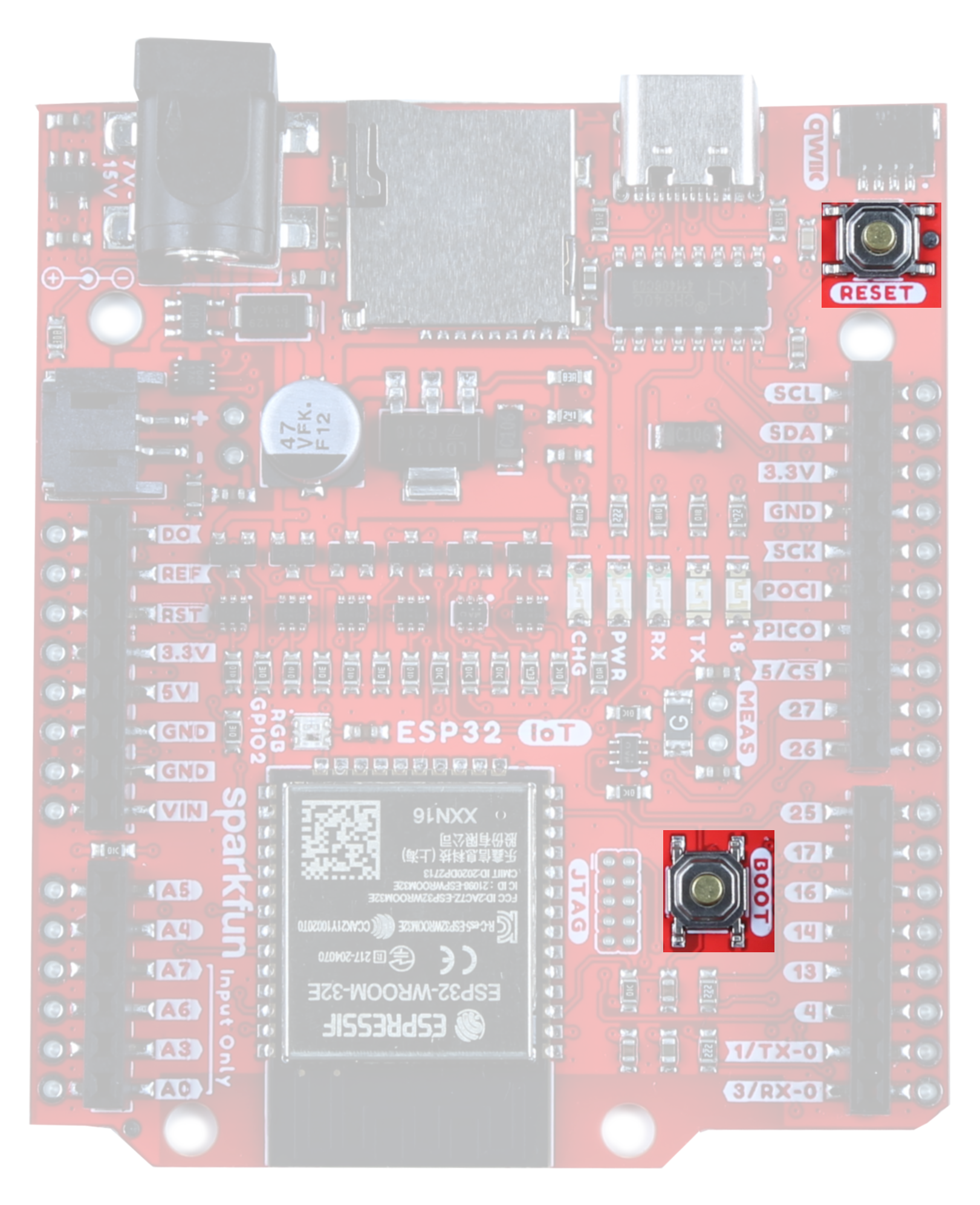
Boot and Reset Buttons
These buttons are par for the course, and pretty handy. The Reset Button allows the user to reset the program running on the ESP32 without unplugging the board. The Boot Button allows the user to manually put the board into Bootloader Mode.
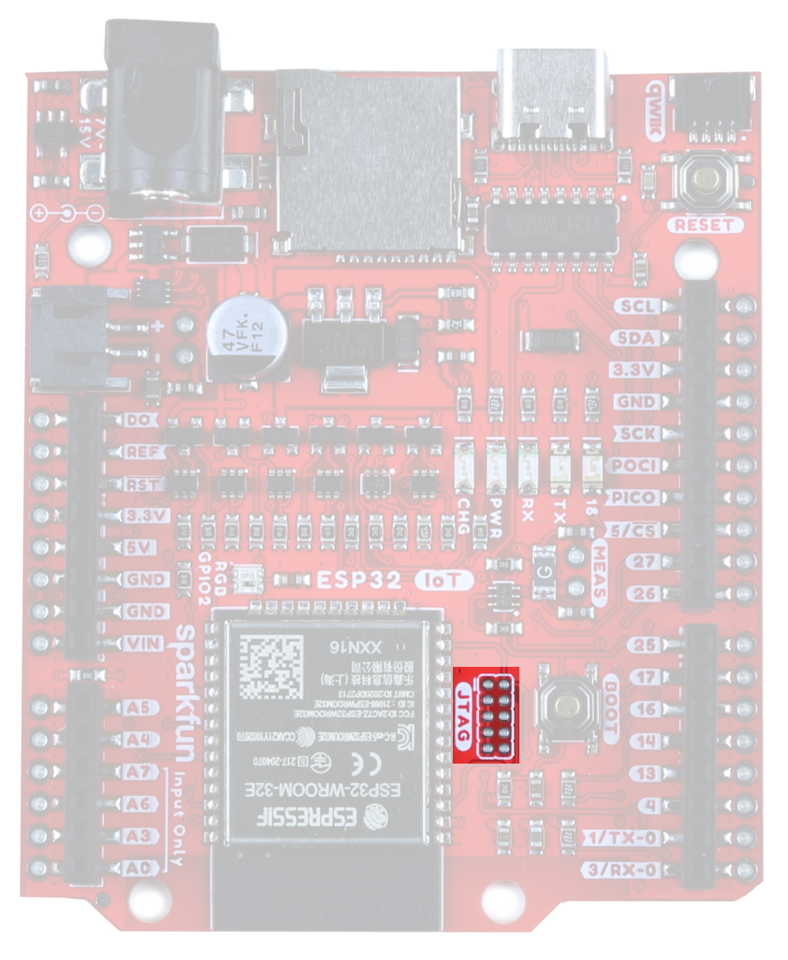
JTAG
If you choose to use an external programmer, the JTAG pins highlighted here will allow you to connect.
The TMS and TCK pins (pins 13 and 14, respectively) are connected by default to the JTAG pins. Open these jumpers to disconnect these two pins from the JTAG.
 |
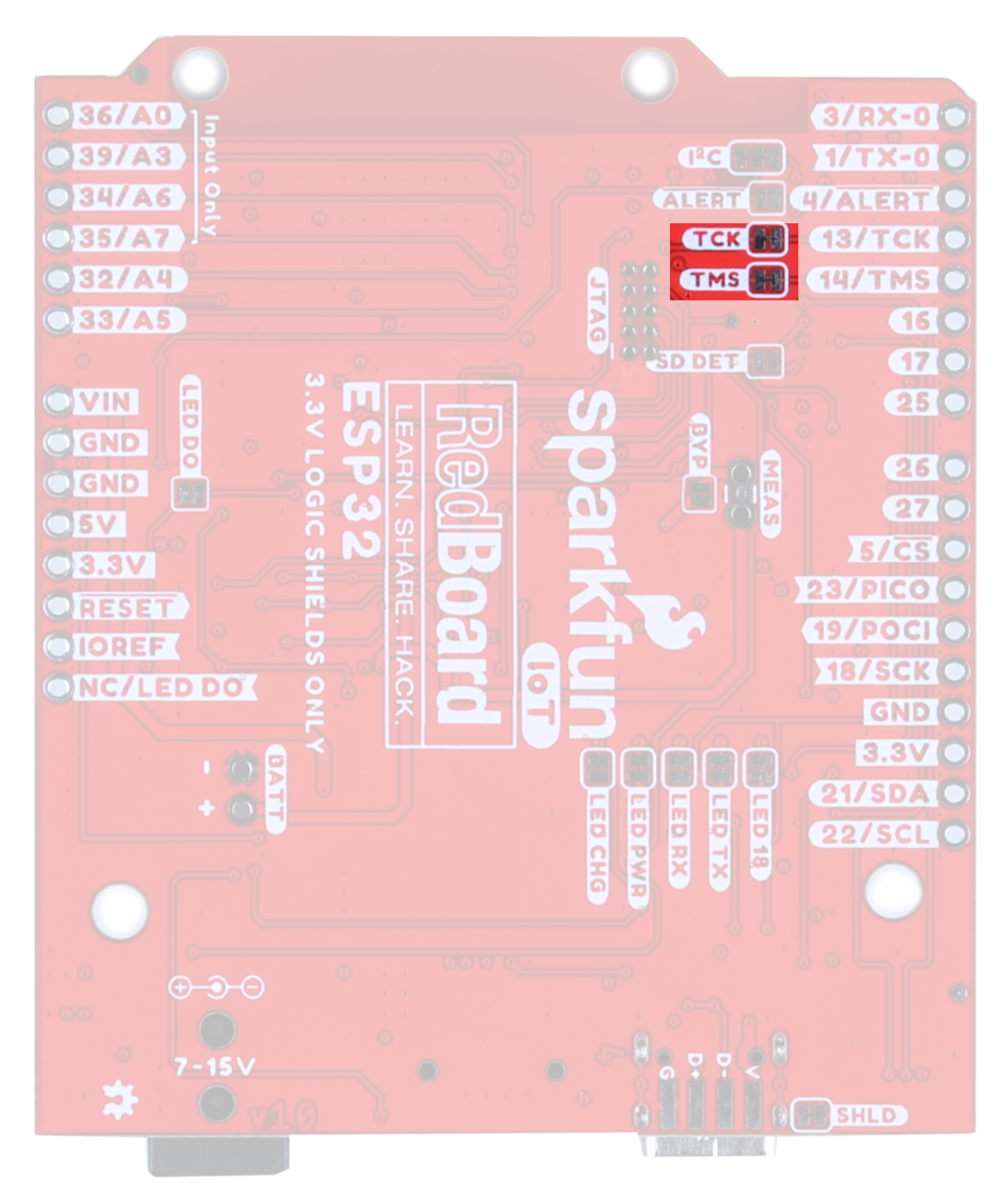 |
| JTAG PTH | TMS/TCS Jumper |
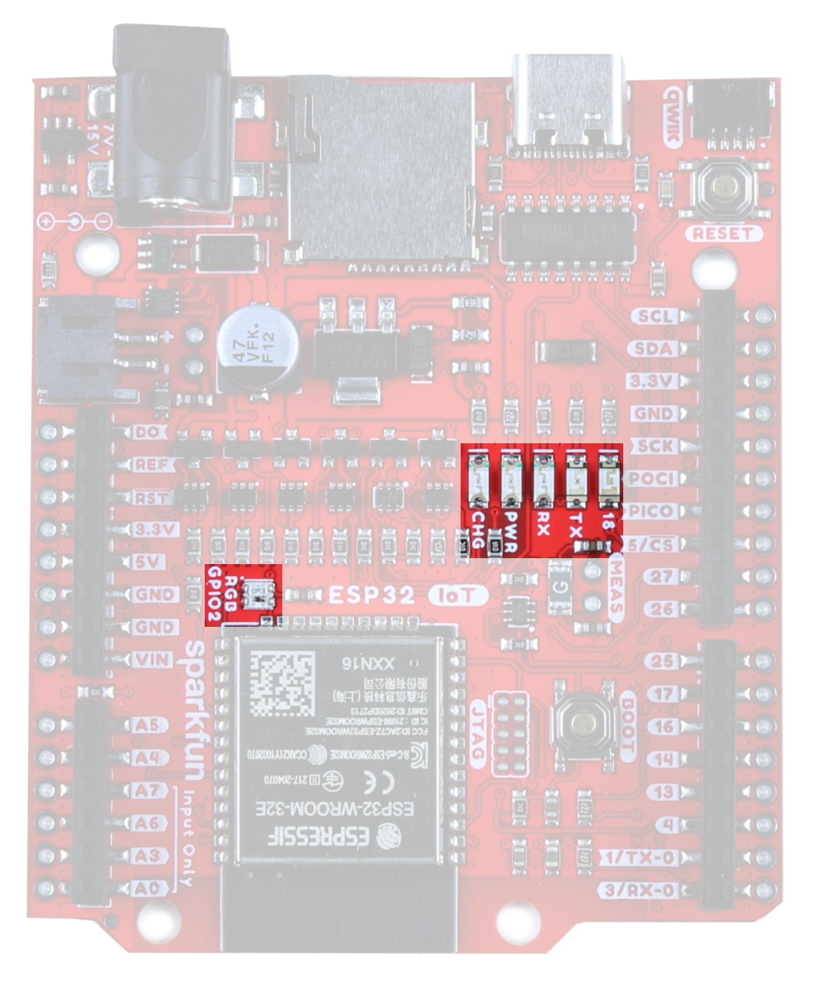
LEDs
There are a number of LEDs on this board;
- CHG - This LED lights up when the attached LiPo battery is charging. Note that when no battery is connected, it is normal for this LED to flicker a bit.
- PWR - Got power? This sucker lights up.
- RX/TX - UART indicators
- 18 - This is the general Status LED. It is connected to the SCK pin.
- RGB GPIO2 - WS2812 LED
The jumpers highlighted here disable the associated LEDs on the front of the board. Closing the LED DO jumper enables users to chain the output of the onboard WS2812 via the DO pin.
 |
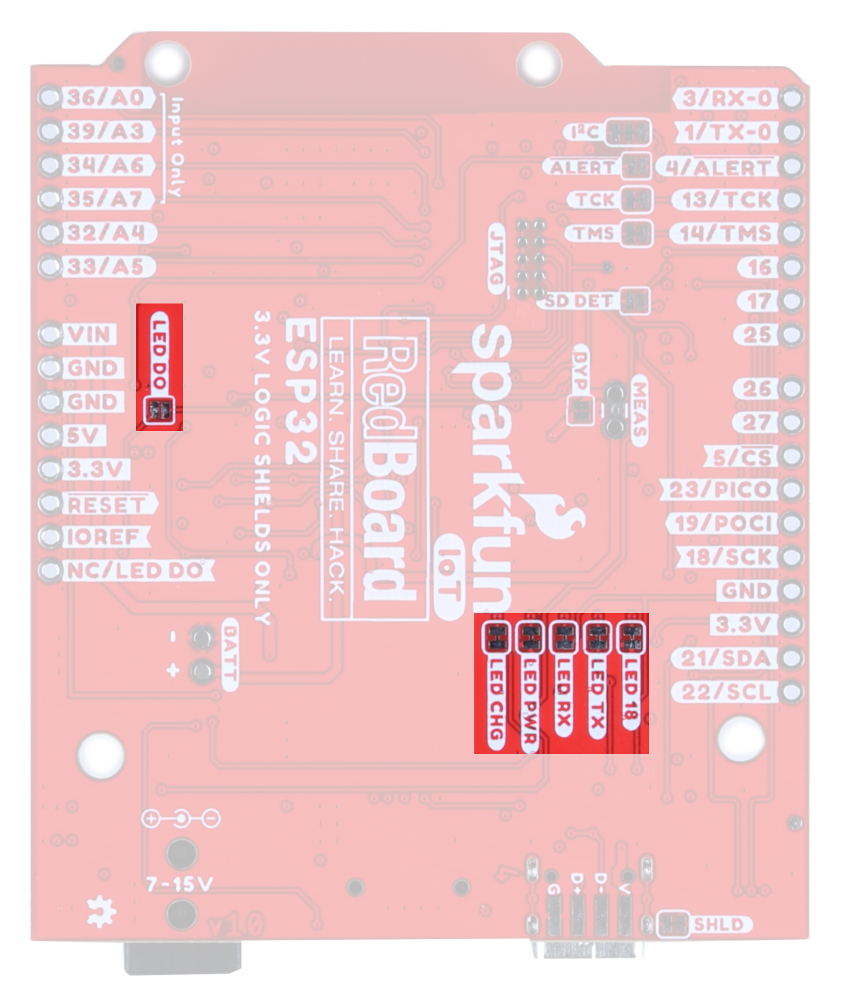 |
| LEDs | LED Jumpers |
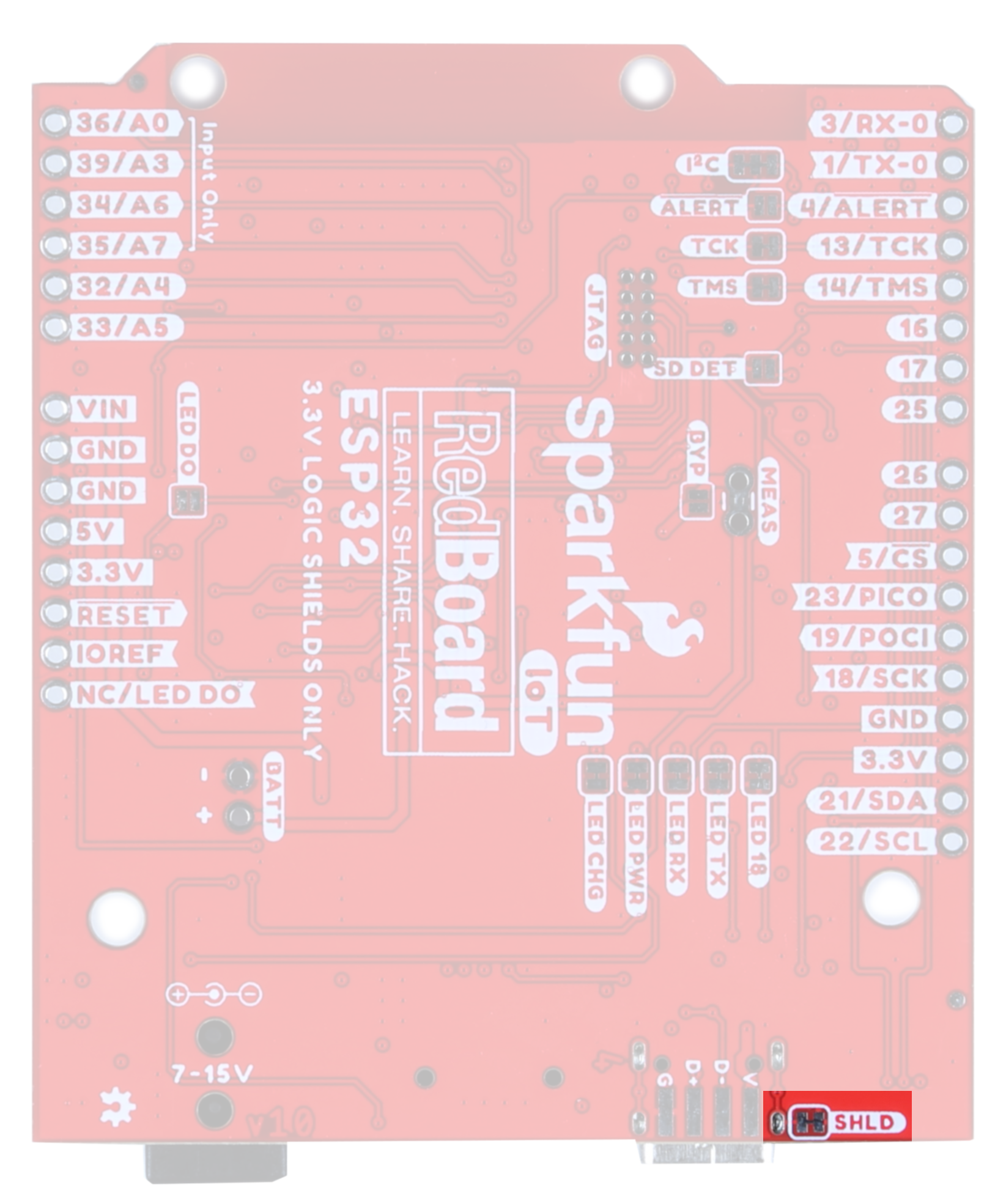
SHLD Jumper
For most applications, the single point grounding of the ESP32 IoT Board at the USB-C connector is sufficient. However, should you run into problems with EMI/EMC, we've provided a jumper that allows you to disconnect the shield from ground at this point.
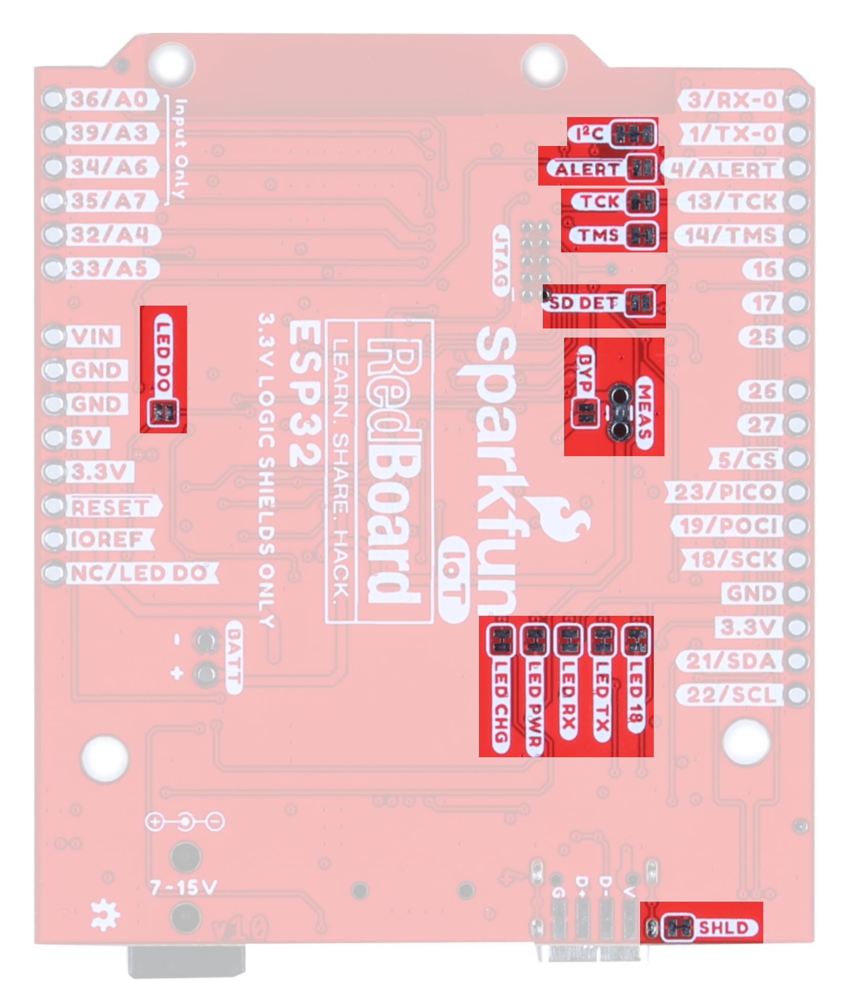
Solder Jumpers
This board has fourteen solder jumpers. The table below outlines each jumper's label, function, default states, and any notes about their use.
| Label | Default State | Function | Notes |
|---|---|---|---|
| ALERT | OPEN | Battery Fuel Gauge Alert | Closing this jumper will enable the Battery Fuel Gauge Alert to be connected to GPIO pin 4. The I2C address to access the battery fuel gauge is 0x36. |
| SD DET | OPEN | SD Card Insertion Detection | The SD card socket is able to detect whether or not an SD card has been inserted. By default, this jumper is open, but should you wish to use this functionality, close this jumper and pull the pin high. When an SD card is inserted, the pin will be pulled low and an interrupt can be triggered to notify the user. |
| I2C | CLOSED | Disables the pull-up resistors on the clock and data pins. | If you are daisy-chaining multiple Qwiic devices, you will want to cut this jumper; if multiple sensors are connected to the bus with the pull-up resistors enabled, the parallel equivalent resistance will create too strong of a pull-up for the bus to operate correctly. As a general rule of thumb, disable all but one pair of pull-up resistors if multiple devices are connected to the bus. |
| TCK/TMS | CLOSED | JTAG TMS and TCK pins | The TMS and TCK pins (pins 13 and 14, respectively) are connected by default to the JTAG pins. Open these jumpers to disconnect these two pins from the JTAG. |
| MEAS | CLOSED | Measures the total current consumption of the board. | Open to measure current draw of the board. Note that any current out of the 5V pin also goes through this jumper. |
| BYP | OPEN | PTC Fuse Bypass Jumper | This is the penny in the fuse jumper. Closing this will allow you to draw more than 1.5A of current. Only close this if you know what you're doing! |
| LED DO | OPEN | Jumper to allow user to chain the output of DO | Allows the user to chain the ouput of the onboard WS2812 |
| LED 18 | CLOSED | General Status LED | Open to disable the labeled LED. Helps reduce the total current draw. |
| LED TX | CLOSED | UART TX Line | |
| LED RX | CLOSED | UART RX Line | |
| LED PWR | CLOSED | Board Power | |
| CHG | CLOSED | LiPo Charge Circuit | |
| SHLD | CLOSED | Jumper to select USB shield grounding option. | Default connects the connector shield to ground. |
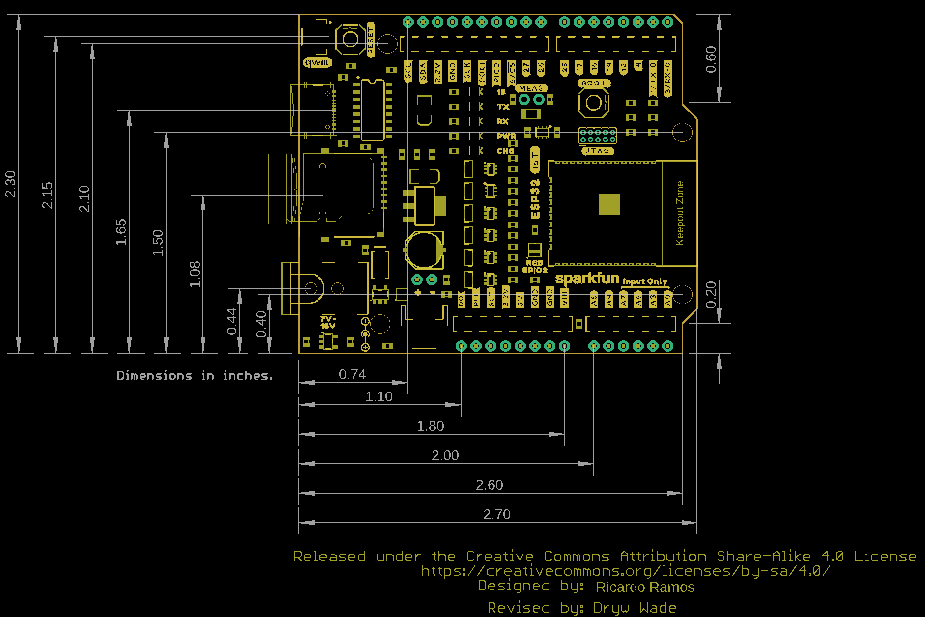
Board Measurements
This board measures 2.3" by 2.7".