IoT RedBoard ESP32 Development Board Hookup Guide
 SparkFro
 Introduction
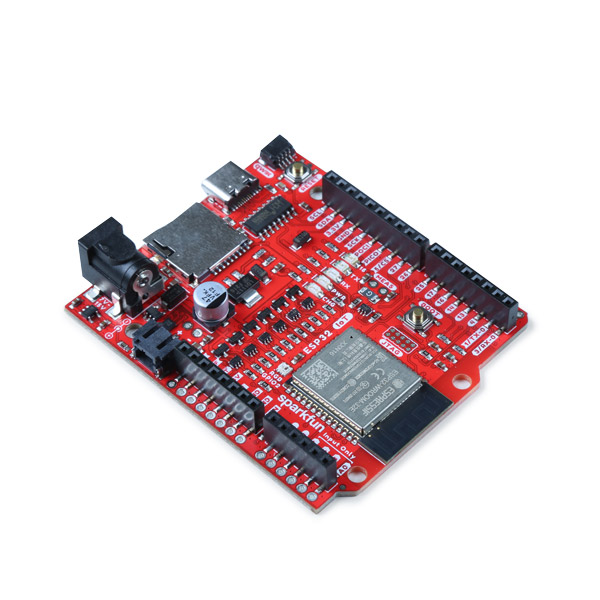
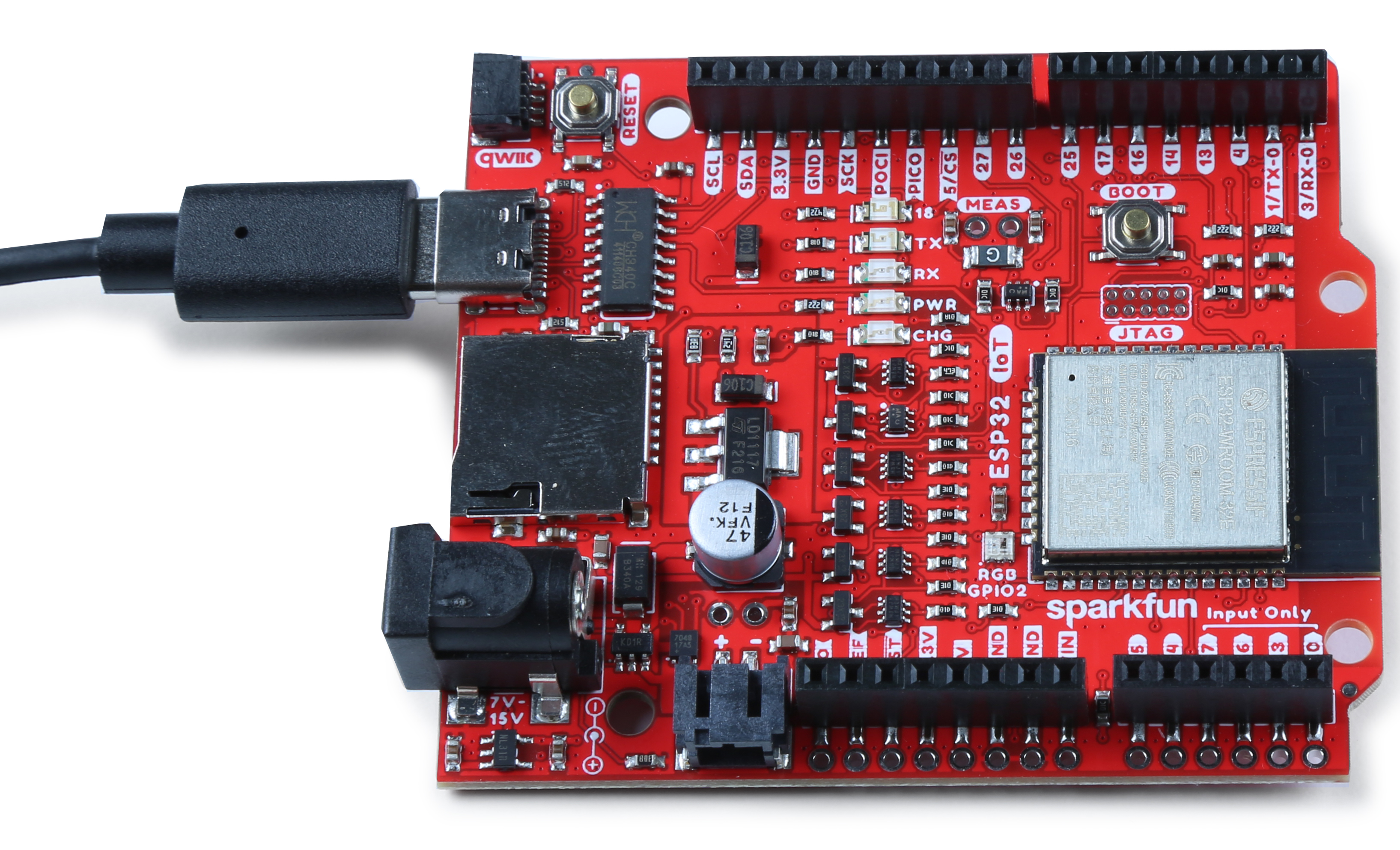
The SparkFun IoT RedBoard is an ESP32 Development Board that includes everything but the kitchen sink! Espressif's ESP32 WROOM is a powerful WiFi and Bluetooth® MCU module that targets a wide variety of applications. At the core of this module is the ESP32-D0WDQ6 chip which is designed to be both scalable and adaptive. The IoT RedBoard can target a wide variety of applications, ranging from low-power sensor networks to the most demanding tasks, such as voice encoding, music streaming, and MP3 decoding. The IoT RedBoard also utilizes our handy Qwiic Connect System which means no soldering or shields are required to connect it to the rest of your system!
The USB-to-serial is achieved with a USB-C connector with through hole anchoring and the ubiquitous CH340G requiring fewer driver installs. We've included 3.3V voltage translation and a Qwiic connector to the edge of the board to allow for quick and seamless connection to our ever-growing line of I2C based Qwiic products. The board even includes a microSD socket if your application requires you to log and save data to a memory card. For remote power, we have included a 2-pin JST connector to attach a single cell, LiPo battery. There's also a built-in LiPo charge IC (MCP73831) and fuel gauge (MAX17048).
The operating system is freeRTOS with LwIP; TLS 1.2 with hardware acceleration is built in as well. Secure (encrypted) over the air (OTA) upgrade is also supported, so that users can upgrade their products even after their release, at minimum cost and effort.
Let's dive in and see what this baby can do!
Required Materials
To follow along with this tutorial, you will need the following materials. You may not need everything though depending on what you have. Add it to your cart, read through the guide, and adjust the cart as necessary.
Suggested Reading
If you aren’t familiar with the following concepts, we recommend checking out these tutorials before continuing.
How to Solder: Through-Hole Soldering
Serial Communication
Serial Peripheral Interface (SPI)
Pulse Width Modulation
Logic Levels
I2C
Analog vs. Digital
How to Work with Jumper Pads and PCB Traces
Installing Arduino IDE
ESP32 Thing Plus Hookup Guide
Installing Board Definitions in the Arduino IDE
Hardware Overview
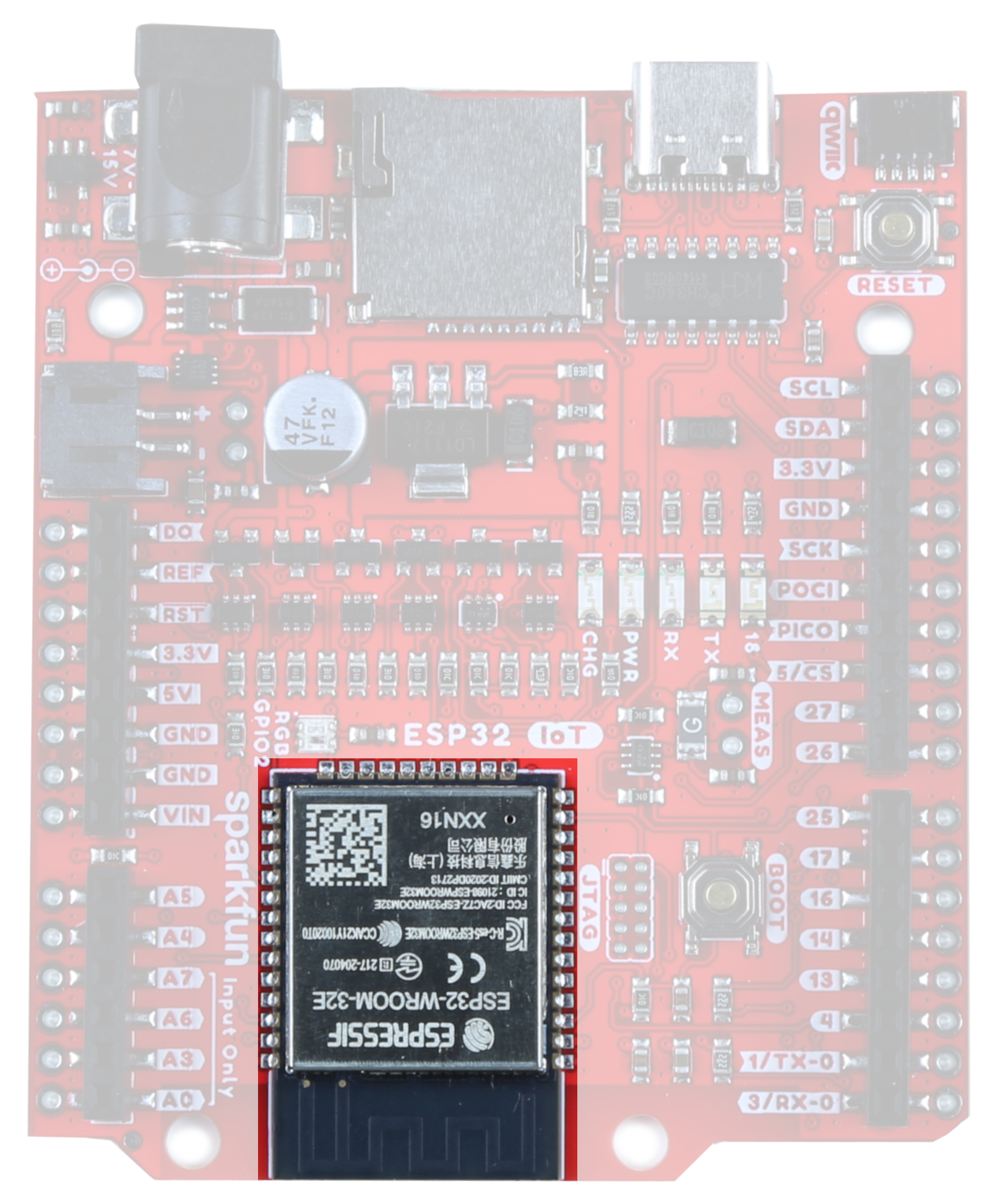
ESP32
At the core of the module is the ESP32-D0WD-V3 chip. The embedded chip is designed to be scalable and adaptive. There are two CPU cores that can be individually controlled, and the CPU clock frequency is adjustable from 80 MHz to 240 MHz. The chip also has a low-power coprocessor that can be used instead of the CPU to save power while performing tasks that do not require much computing power, such as monitoring of peripherals. ESP32 integrates a rich set of peripherals, including capacitive touch sensors, SD card interface, Ethernet, high-speed SPI, UART, I2S and I2C. Check out the datasheet for more info.
Power
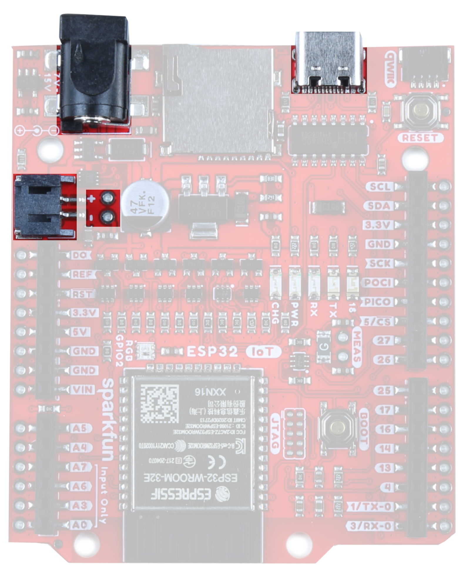
There are a number of different ways to power the SparkFun ESP32 IoT Dev Board:
- USB-C
- barrel jack connector
- LiPo battery charge circuit and fuel gauge.
- power pins broken out on the edge of the board
The easiest way (which will also allow you to program your board) is to simply plug it into your computer via USB-C. If you choose to power it via USB, the other end of the USB cable can be connected to either a computer or a 5V (regulated) USB wall charger. Otherwise, should you choose to use the barrel jack, any wall adapter connected to this jack should supply a DC voltage between 7 and 15V. You could also power the board via the header pins. Note that the GPIO pins are NOT 5V tolerant! Make sure that your voltage is regulated when applying power to the 5V or 3.3V pins, respectively.
Charge Circuit
For those using a LiPo battery, note that there is a LiPo charging circuit on the board! By default, RPROG=2k and ICHG=500mA. To calculate the charge current, use the following equation:

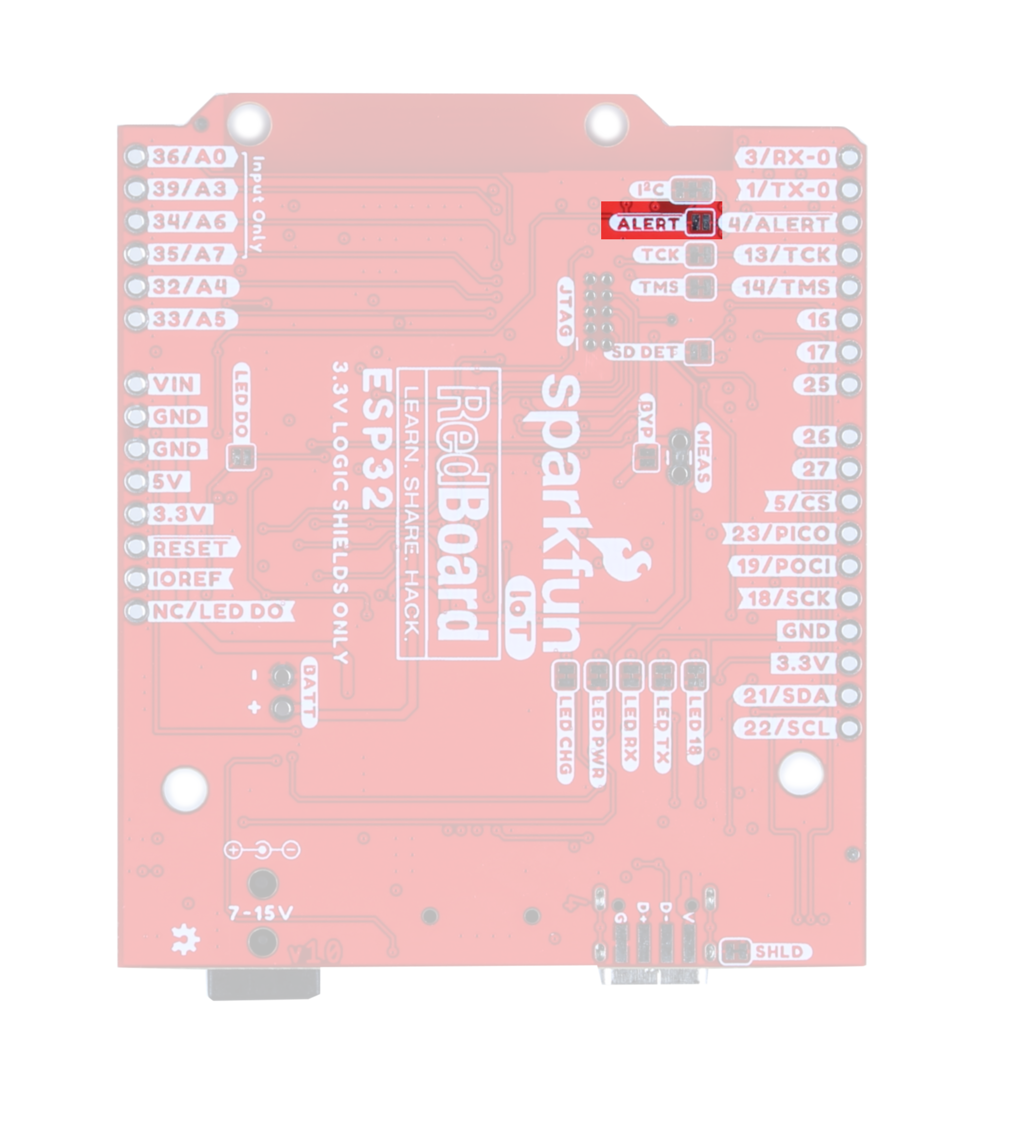
ALERT Jumper
If you are powering your board with a LiPo battery, closing this jumper will enable the Battery Fuel Gauge Alert to be connected to GPIO pin 4. The I2C address to access the battery fuel gauge is 0x36.
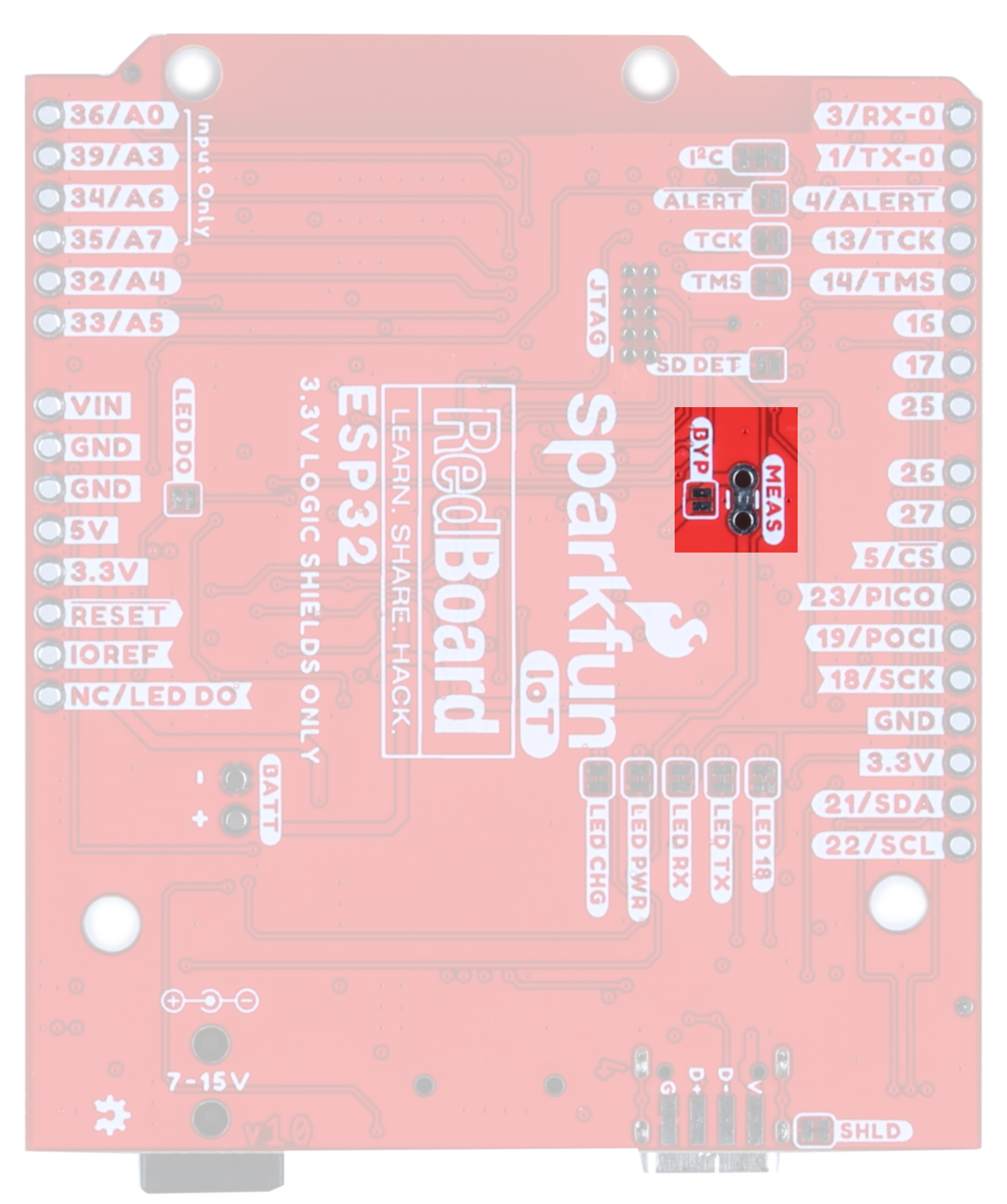
Current Measurement & BYP Jumper
To enable measurements and determine how long your battery might last, we've added a NC (normally closed) jumper between the two MEAS PTH pins. By cutting this jumper, the VDD trace to the module is interrupted. Soldering in a male jumper or wires into the accompanying holes will give you the ability to insert a current meter and precisely monitor how much current your application is consuming.
Note that we have also added a PTC fuse bypass jumper - this fuse will trip around 1.5A to protect anything from frying; if you really need more current, close the BYP jumper to bypass the fuse.
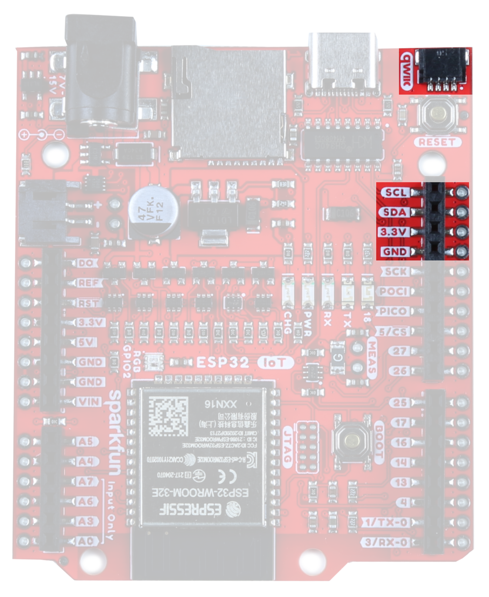
Qwiic Functionality
Our Qwiic Ecosystem makes sensors pretty much plug and play. The Qwiic connector provides power and I2C connectivity simultaneously. In addition, we've broken out the I2C functionality to PTH.
In addition, The IoT RedBoard ESP32 Development Board comes equipped with pull-up resistors on the clock and data pins. If you are daisy-chaining multiple Qwiic devices, you will want to cut this jumper; if multiple sensors are connected to the bus with the pull-up resistors enabled, the parallel equivalent resistance will create too strong of a pull-up for the bus to operate correctly. As a general rule of thumb, disable all but one pair of pull-up resistors if multiple devices are connected to the bus. To disable the pull up resistors, use an X-acto knife to cut the joint between the two jumper pads highlighted here.
 |
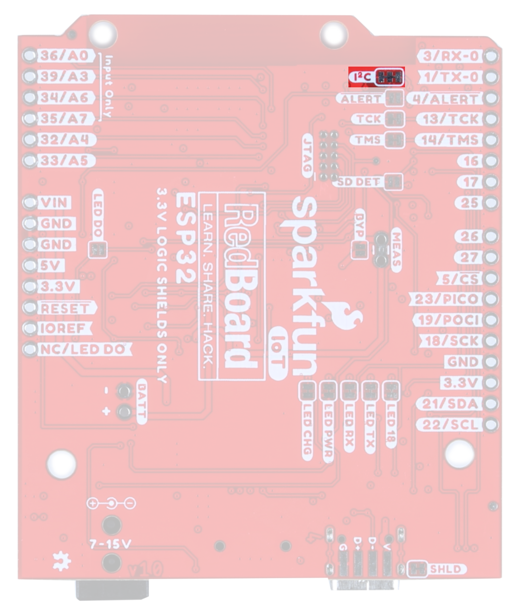 |
| I2C Pins and Qwiic Connector | I2C Jumper |
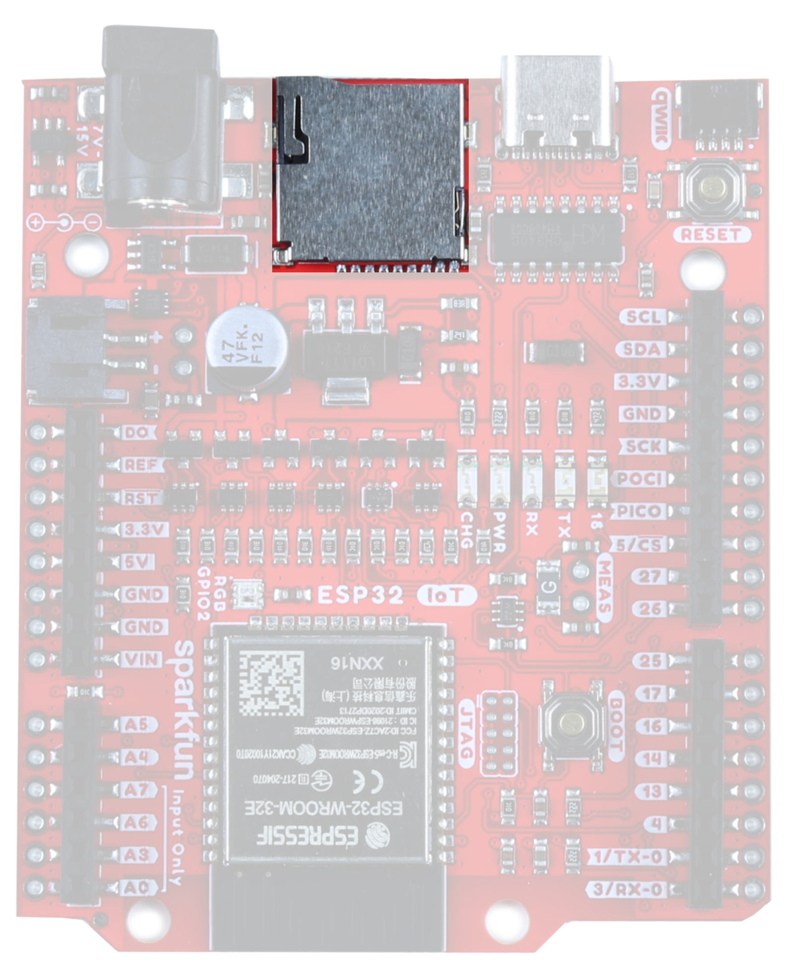
MicroSD
The board includes a microSD socket if your application requires you to log and save data to a memory card.
The SD card socket is able to detect whether or not an SD card has been inserted. By default, this jumper is open, but should you wish to use this functionality, close this jumper and pull the pin high. When an SD card is inserted, the pin will be pulled low and an interrupt can be triggered to notify the user.
 |
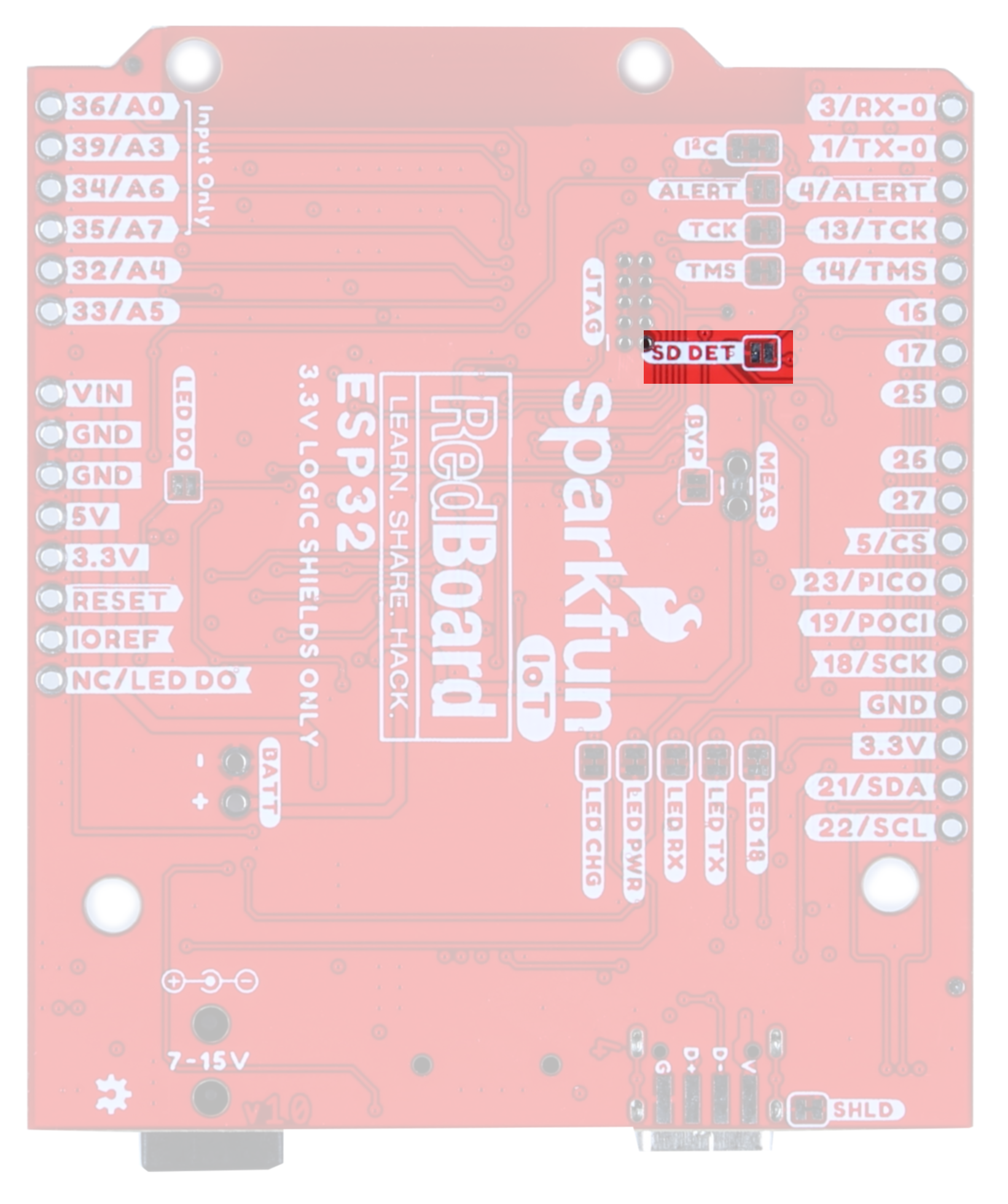 |
| MicroSD card slot | SDDET Jumper |
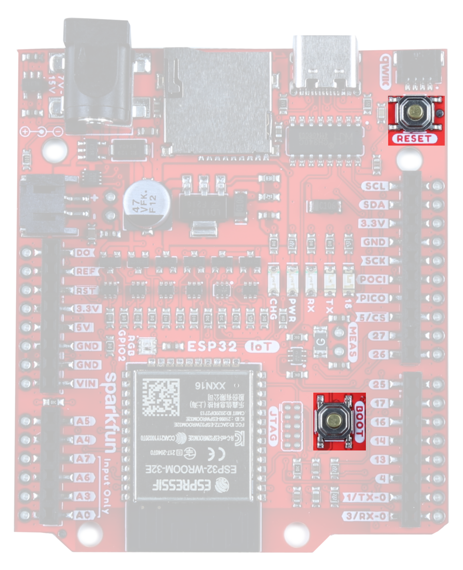
Boot and Reset Buttons
These buttons are par for the course, and pretty handy. The Reset Button allows the user to reset the program running on the ESP32 without unplugging the board. The Boot Button allows the user to manually put the board into Bootloader Mode.
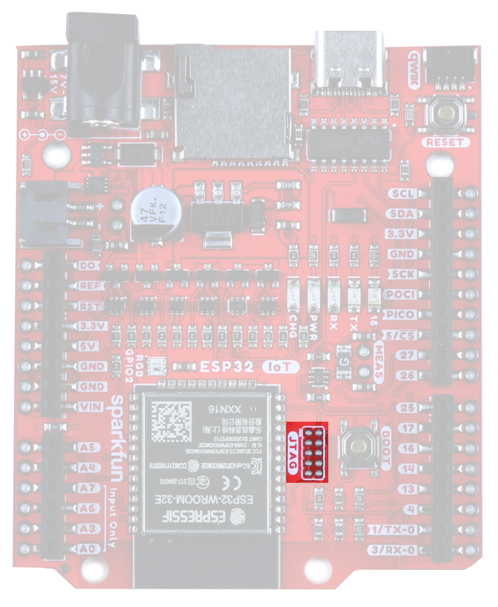
JTAG
If you choose to use an external programmer, the JTAG pins highlighted here will allow you to connect.
The TMS and TCK pins (pins 13 and 14, respectively) are connected by default to the JTAG pins. Open these jumpers to disconnect these two pins from the JTAG.
 |
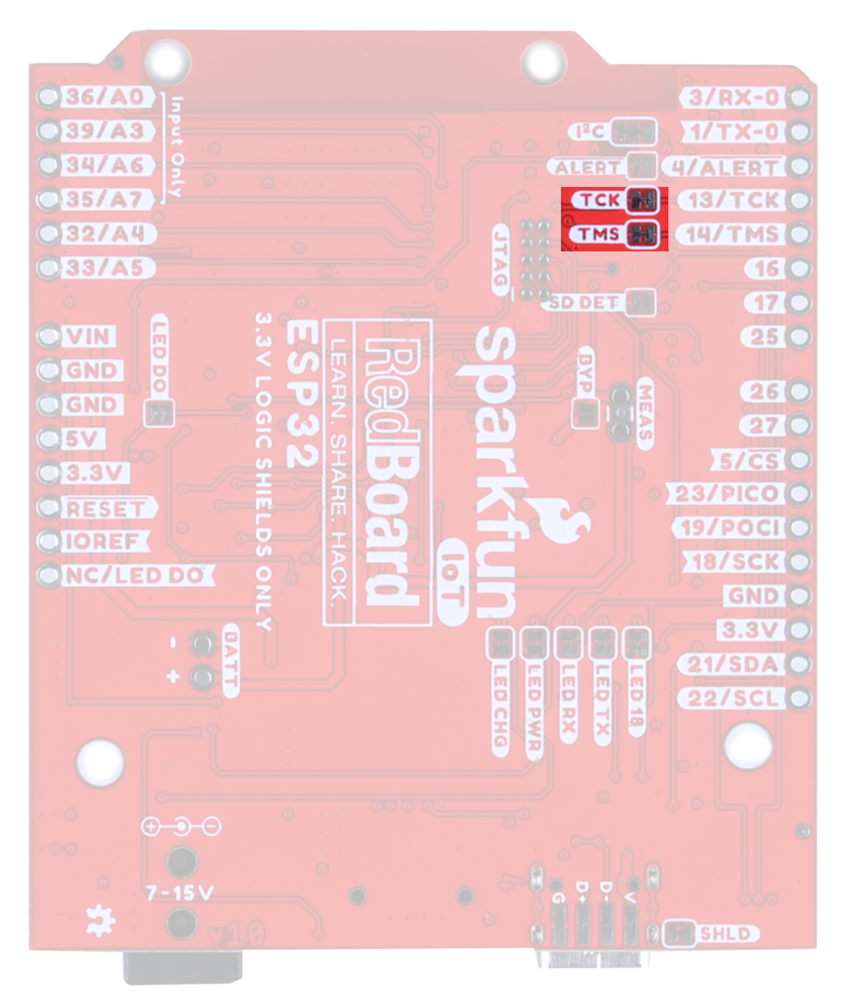 |
| JTAG PTH | TMS/TCS Jumper |
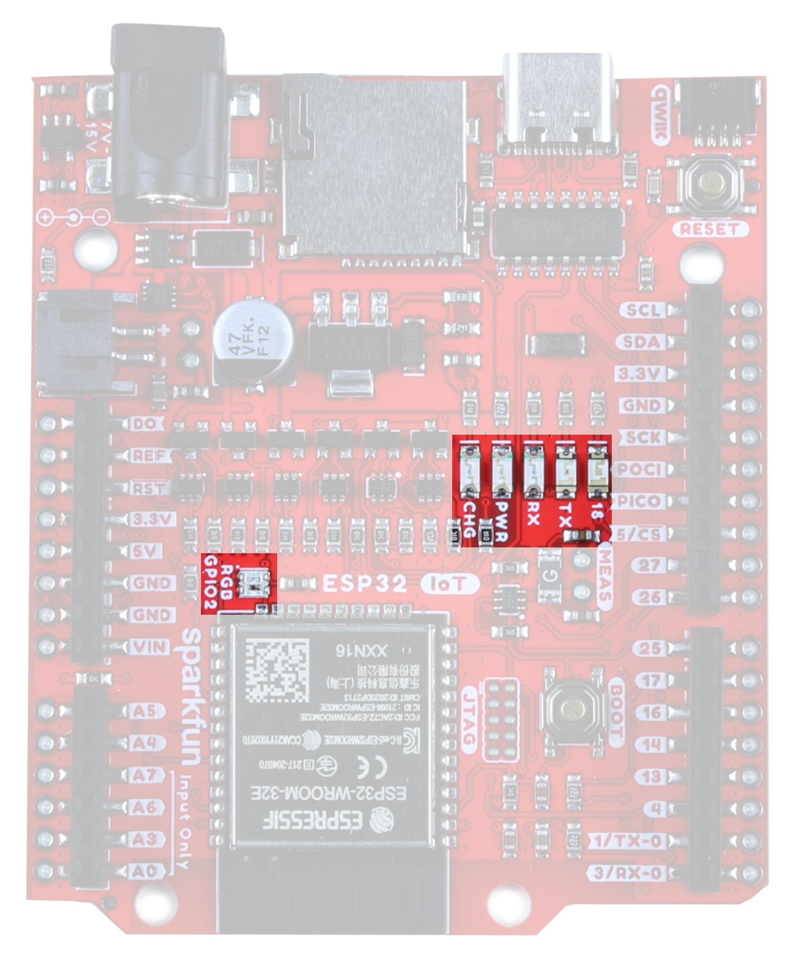
LEDs
There are a number of LEDs on this board;
- CHG - This LED lights up when the attached LiPo battery is charging. Note that when no battery is connected, it is normal for this LED to flicker a bit.
- PWR - Got power? This sucker lights up.
- RX/TX - UART indicators
- 18 - This is the general Status LED. It is connected to the SCK pin.
- RGB GPIO2 - WS2812 LED
The jumpers highlighted here disable the associated LEDs on the front of the board. Closing the LED DO jumper enables users to chain the output of the onboard WS2812 via the DO pin.
 |
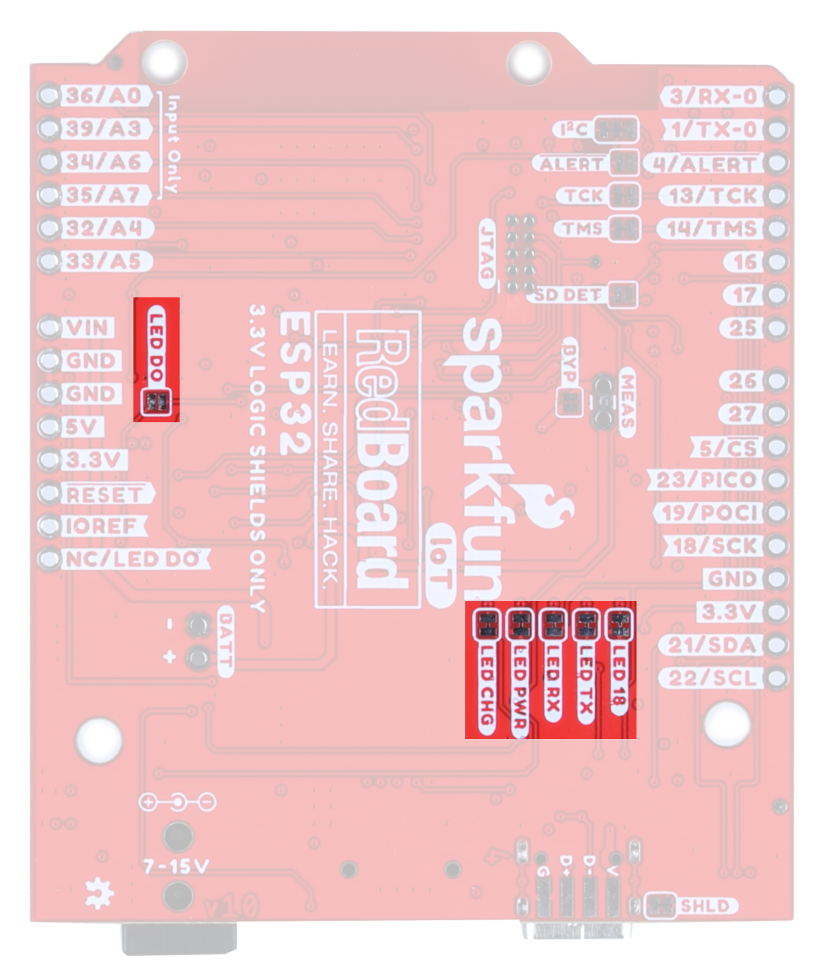 |
| LEDs | LED Jumpers |
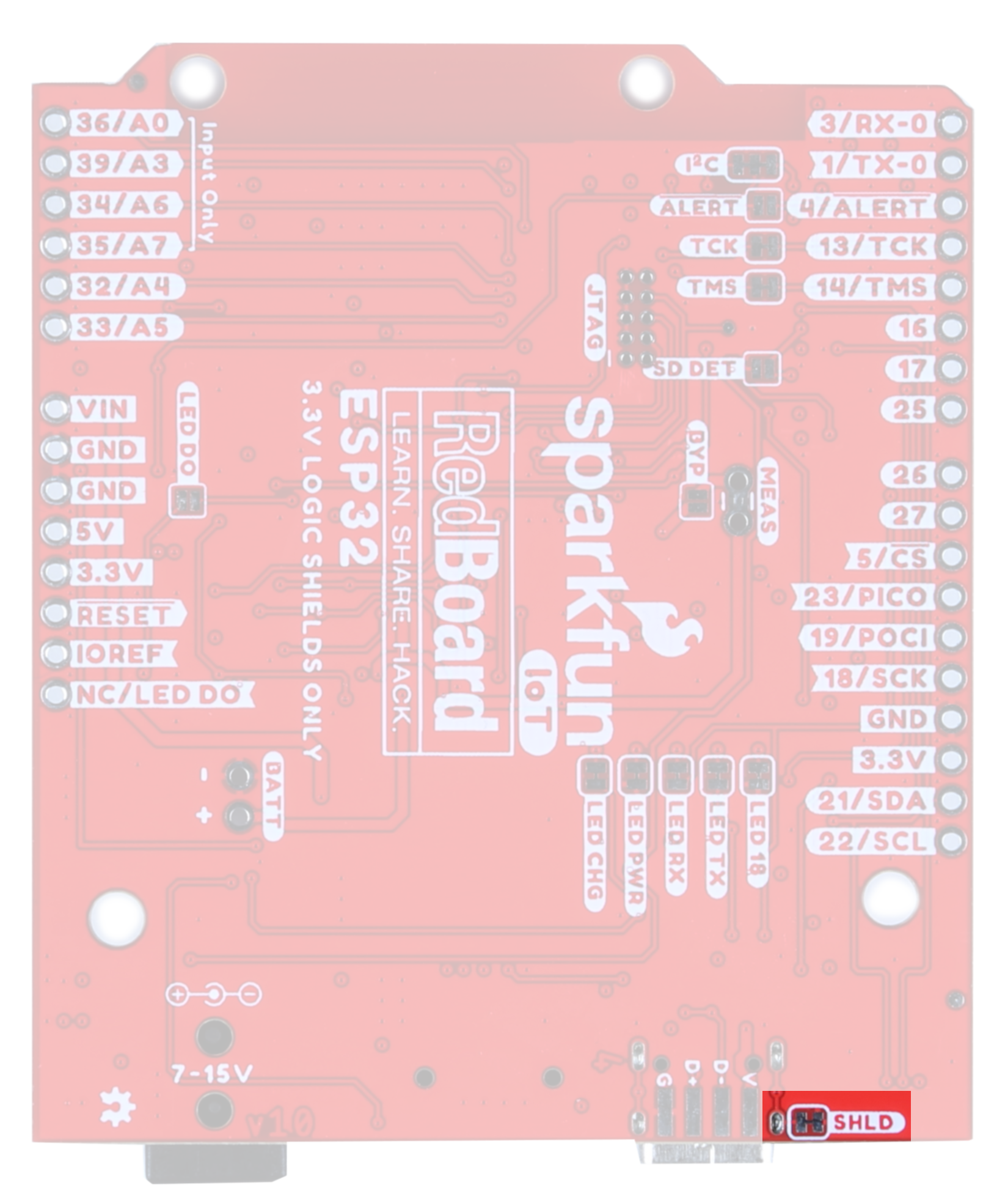
SHLD Jumper
For most applications, the single point grounding of the ESP32 IoT Board at the USB-C connector is sufficient. However, should you run into problems with EMI/EMC, we've provided a jumper that allows you to disconnect the shield from ground at this point.
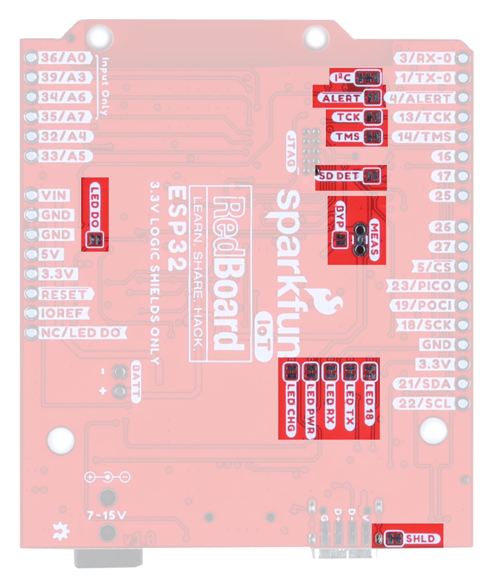
Solder Jumpers
This board has fourteen solder jumpers. The table below outlines each jumper's label, function, default states, and any notes about their use.
| Label | Default State | Function | Notes |
|---|---|---|---|
| ALERT | OPEN | Battery Fuel Gauge Alert | Closing this jumper will enable the Battery Fuel Gauge Alert to be connected to GPIO pin 4. The I2C address to access the battery fuel gauge is 0x36. |
| SD DET | OPEN | SD Card Insertion Detection | The SD card socket is able to detect whether or not an SD card has been inserted. By default, this jumper is open, but should you wish to use this functionality, close this jumper and pull the pin high. When an SD card is inserted, the pin will be pulled low and an interrupt can be triggered to notify the user. |
| I2C | CLOSED | Disables the pull-up resistors on the clock and data pins. | If you are daisy-chaining multiple Qwiic devices, you will want to cut this jumper; if multiple sensors are connected to the bus with the pull-up resistors enabled, the parallel equivalent resistance will create too strong of a pull-up for the bus to operate correctly. As a general rule of thumb, disable all but one pair of pull-up resistors if multiple devices are connected to the bus. |
| TCK/TMS | CLOSED | JTAG TMS and TCK pins | The TMS and TCK pins (pins 13 and 14, respectively) are connected by default to the JTAG pins. Open these jumpers to disconnect these two pins from the JTAG. |
| MEAS | CLOSED | Measures the total current consumption of the board. | Open to measure current draw of the board. Note that any current out of the 5V pin also goes through this jumper. |
| BYP | OPEN | PTC Fuse Bypass Jumper | This is the penny in the fuse jumper. Closing this will allow you to draw more than 1.5A of current. Only close this if you know what you're doing! |
| LED DO | OPEN | Jumper to allow user to chain the output of DO | Allows the user to chain the ouput of the onboard WS2812 |
| LED 18 | CLOSED | General Status LED | Open to disable the labeled LED. Helps reduce the total current draw. |
| LED TX | CLOSED | UART TX Line | |
| LED RX | CLOSED | UART RX Line | |
| LED PWR | CLOSED | Board Power | |
| CHG | CLOSED | LiPo Charge Circuit | |
| SHLD | CLOSED | Jumper to select USB shield grounding option. | Default connects the connector shield to ground. |
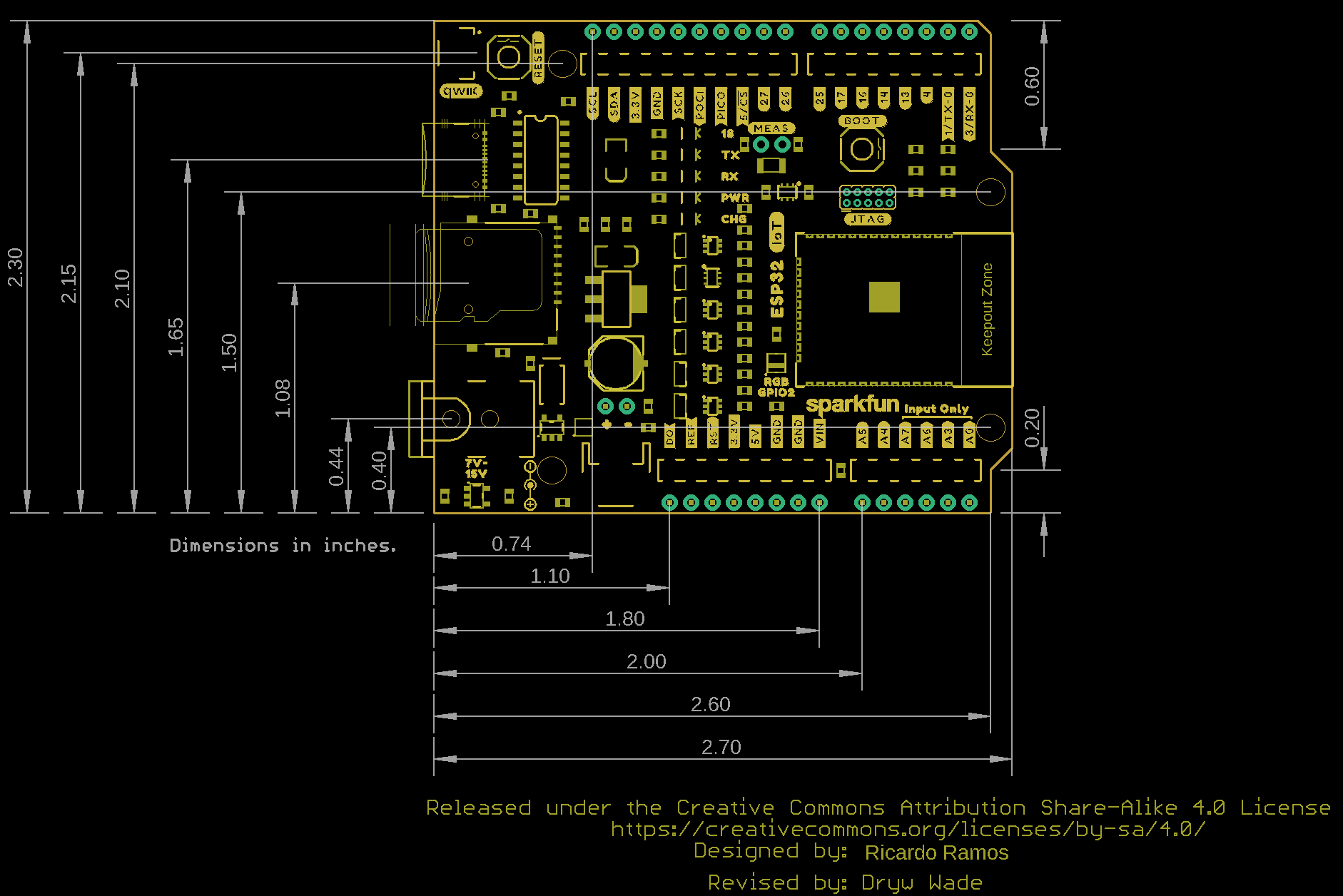
Board Measurements
This board measures 2.3" by 2.7".

Hardware Hookup
Hardware hookup is a breeze! Grab your USB-C cable and plug it into the USB-C port! Voila!
Software Setup and Programming
Install CH340 Drivers
If you've never connected an CH340 device to your computer before, you may need to install drivers for the USB-to-serial converter. Check out our section on "How to Install CH340 Drivers" for help with the installation.
Install Board Definition
Make sure you have the latest ESP32 board definitions installed in the Arduino IDE Boards Manager:
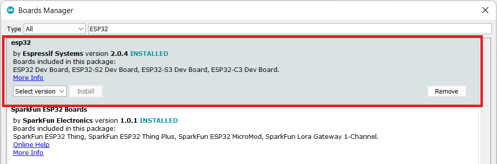
Installing Board Definitions in the Arduino IDE
For more instructions, users can follow this tutorial on Installing Additional Cores provided by Arduino. Users will also need the
.json file for the Espressif Arduino Core:
https://raw.githubusercontent.com/espressif/arduino-esp32/gh-pages/package_esp32_index.json
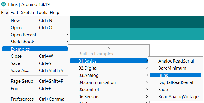
Example 1: Blink
The Blink example is a great benchmark to make sure you've got everything up and running correctly. You can find the example here:
The LED pin is hard coded in this example, so you'll need to change it to pin 18. See the example code below if you need help:
language:c
/*
  Blink

  Turns an LED on for one second, then off for one second, repeatedly.

  Most Arduinos have an on-board LED you can control. On the UNO, MEGA and ZERO
  it is attached to digital pin 13, on MKR1000 on pin 6. LED_BUILTIN is set to
  the correct LED pin independent of which board is used.
  If you want to know what pin the on-board LED is connected to on your Arduino
  model, check the Technical Specs of your board at:
  https://www.arduino.cc/en/Main/Products

  modified 8 May 2014
  by Scott Fitzgerald
  modified 2 Sep 2016
  by Arturo Guadalupi
  modified 8 Sep 2016
  by Colby Newman

  This example code is in the public domain.

  https://www.arduino.cc/en/Tutorial/BuiltInExamples/Blink
*/

#define LED_BUILTIN 18

// the setup function runs once when you press reset or power the board
void setup() {
  // initialize digital pin LED_BUILTIN as an output.
  pinMode(LED_BUILTIN, OUTPUT);
}

// the loop function runs over and over again forever
void loop() {
  digitalWrite(LED_BUILTIN, HIGH);   // turn the LED on (HIGH is the voltage level)
  delay(1000);                       // wait for a second
  digitalWrite(LED_BUILTIN, LOW);    // turn the LED off by making the voltage LOW
  delay(1000);                       // wait for a second
}
Make sure you have the correct Board Selected like so:
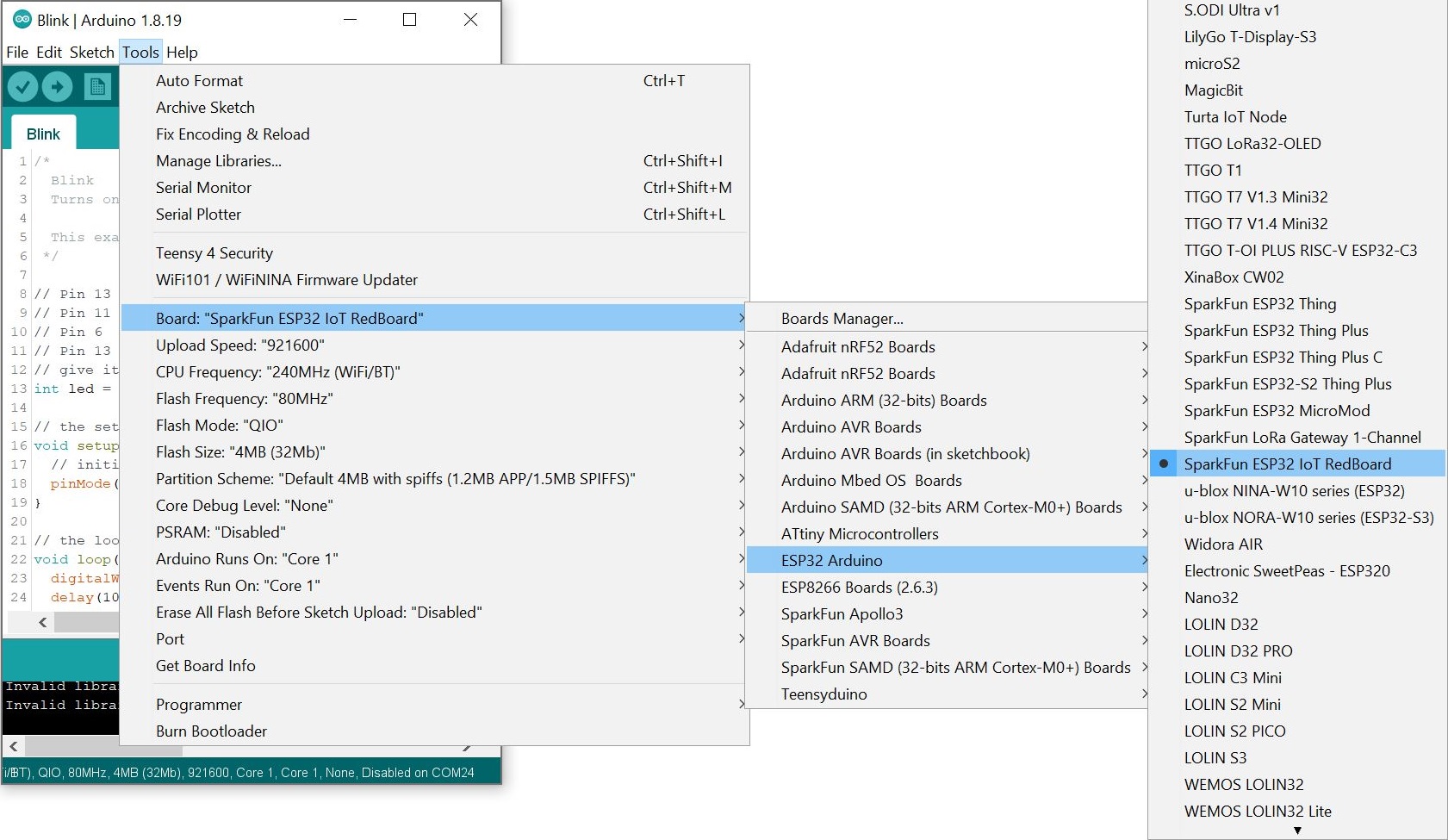
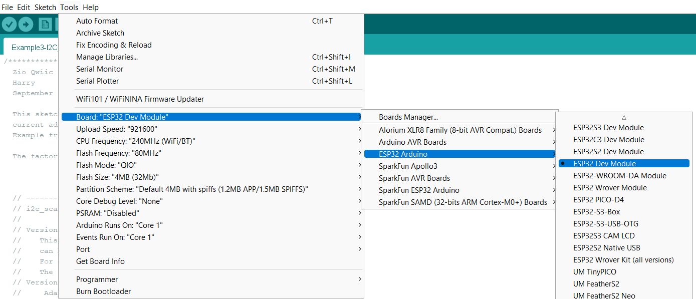
Smash that upload button and if all goes well, you'll see LED 18 blink on and off!
Example 2: WiFi
One of the main selling points of the ESP32 is the Wireless functionality. The Access Point example is a nice standalone demo; you connect to an AP created by the ESP32 (SSID and password are configurable), then connect to a web server running on the ESP32 (must use IP address 192.168.4.1), where the LED can be toggled on/off.
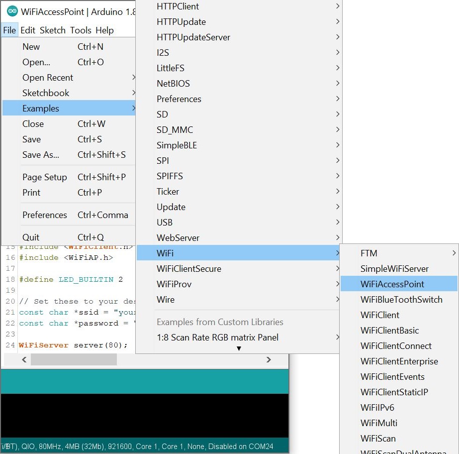
To find this example, go to File > Examples, and under "Examples for SparkFun ESP32 IoT RedBoard" you'll select WiFi > WiFiAccessPoint.
There are a few things you'll need to edit in your example. First, make sure LED_BUILTIN is set to "18". Then you'll need to update your network name and password. MAKE SURE your password is at least 8 characters!
language:c
#define LED_BUILTIN 18

// Set these to your desired credentials.
const char *ssid = "yourAP";
const char *password = "yourPassword"; //This needs to be >= eight characters long
Once these are updated, make sure you have the correct board and port selected, and then upload your code.
Assuming your code uploaded correctly, we can now connect to our Access Point, navigate to the webpage, and turn on and off our LED!
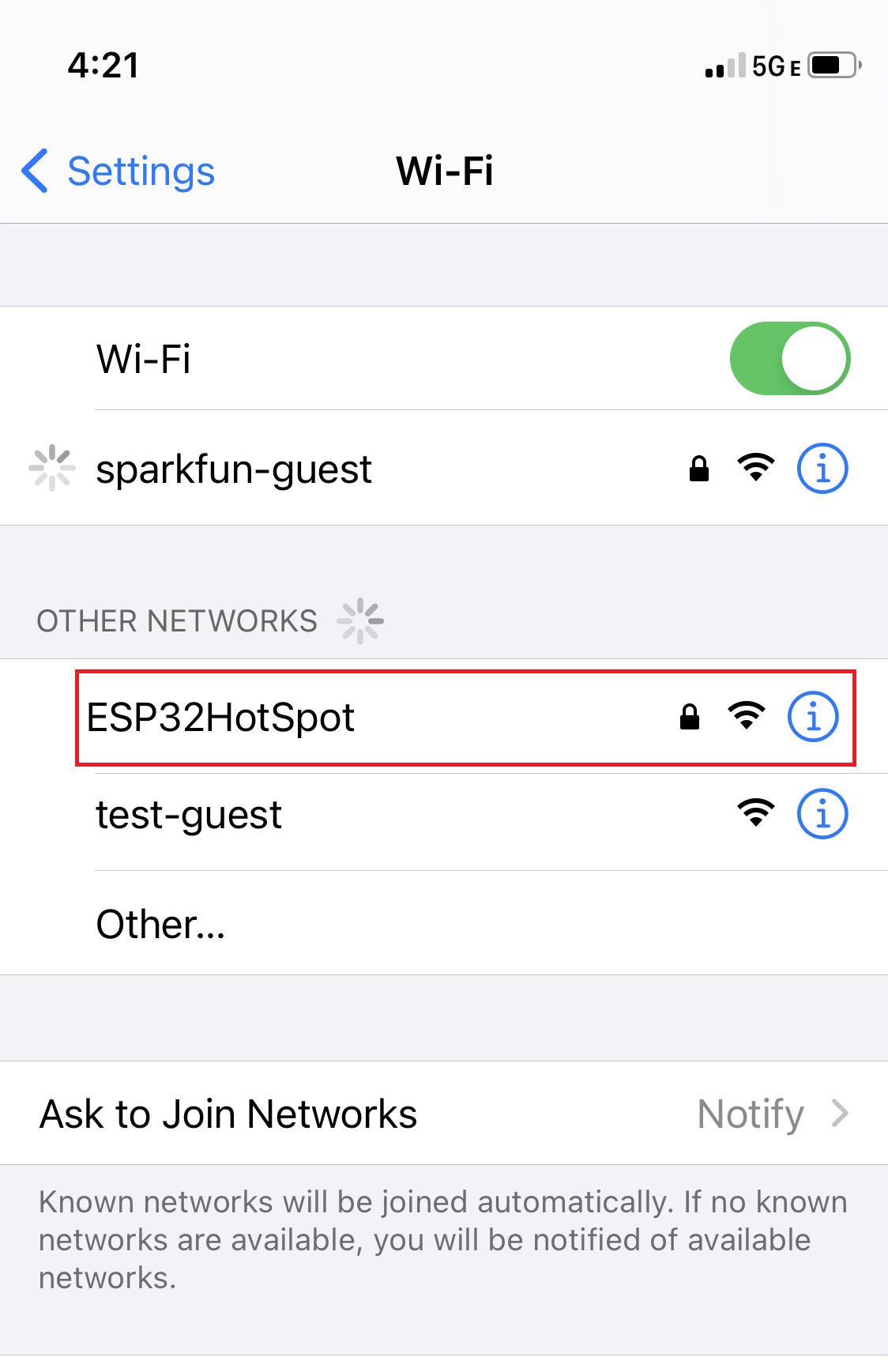
From your phone, computer, or mobile device, navigate to the WiFi networks. Choose the name of the network you created on the ESP32 - I called this the ESP32HotSpot. Connect to that network!
Enter your password:
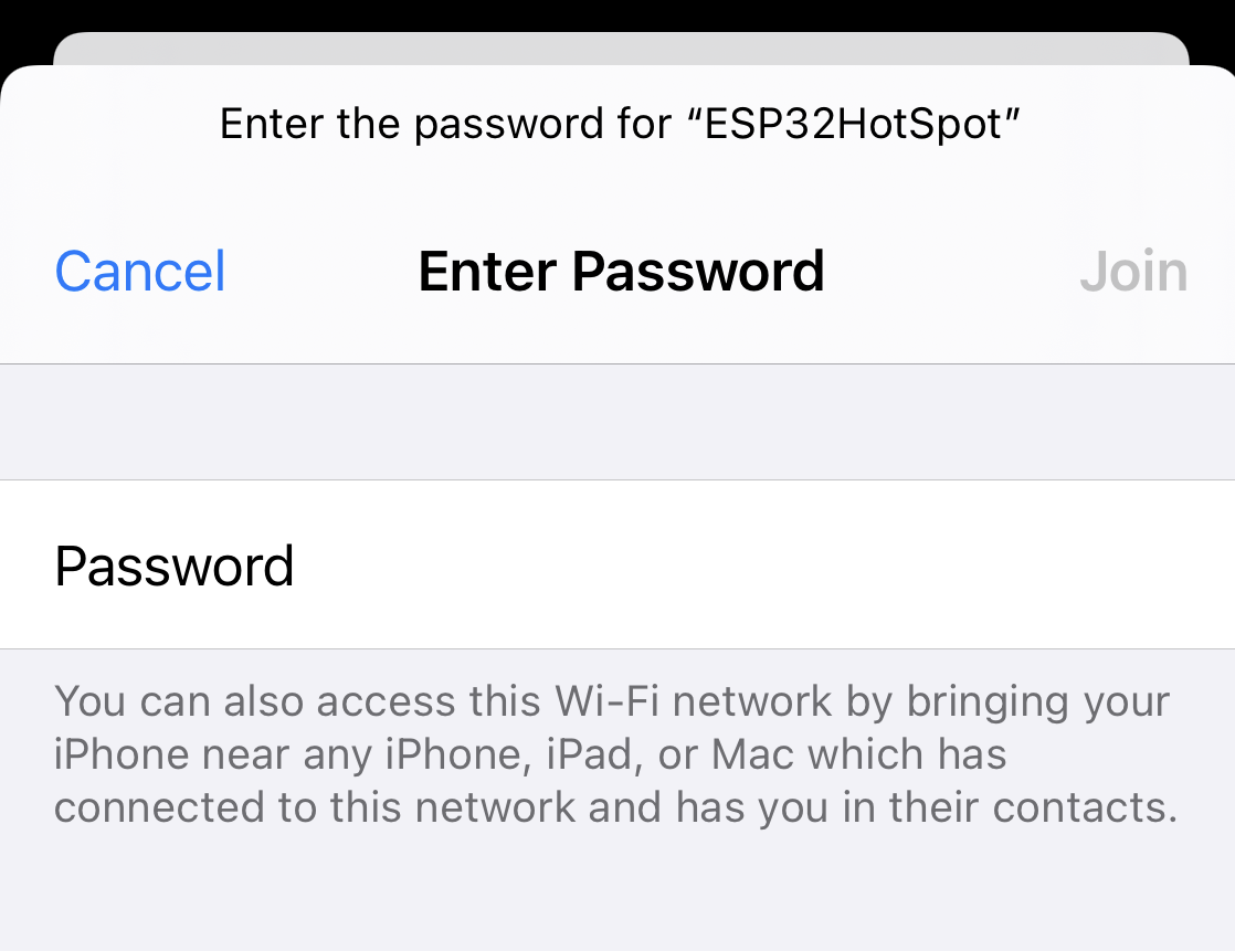
Navigate to 192.168.4.1 in a web browser. You should see the following:
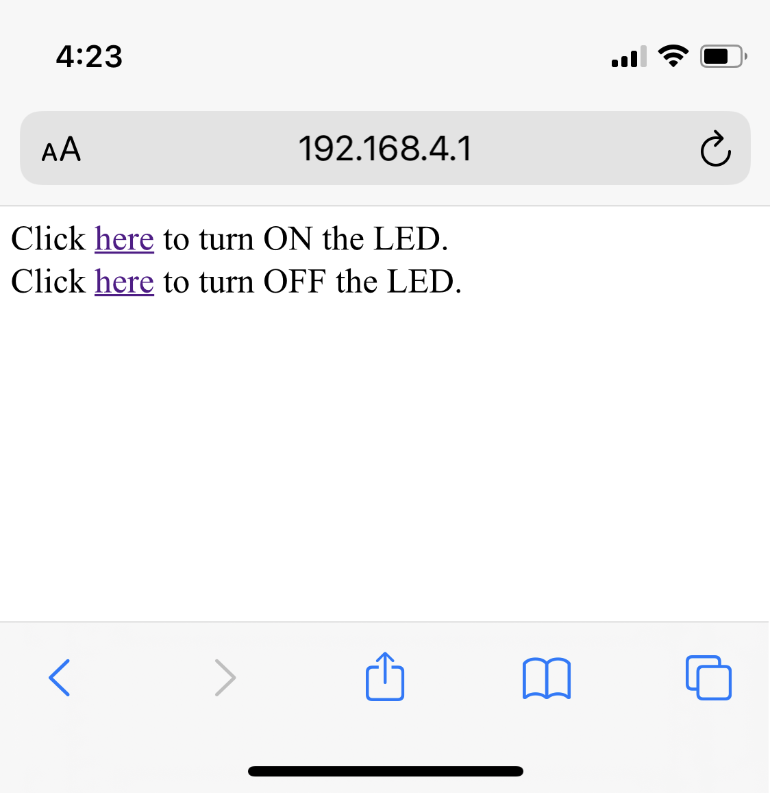
Play with the links to turn LED 18 on and off!
Example 3: SD Card
This built-in example provides a pretty thorough demo of what can be done with Espressif's SD card library (reading/writing files, listing/making directories, etc). You'll need an SD card to get going here. Make sure you gently insert the SD Card into the SD Card slot!
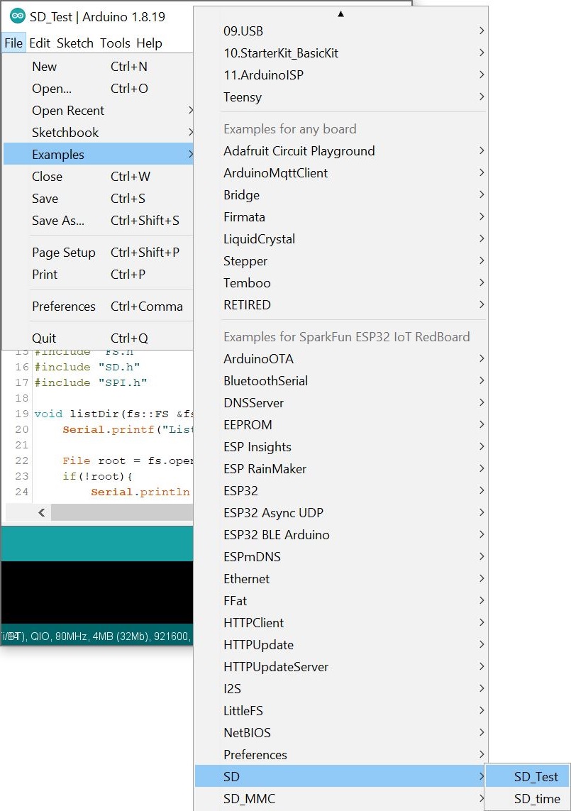
To find the code, go to File > Examples, and under "Examples for ESP32 Dev Module" you'll select SD > SD_Test.
As before, make sure you've got the correct board and port selected, and upload your code.
Once your code has been uploaded, you can open a Serial Monitor to see the output. You should see something like the following (you may have to hit the reset button on your board, depending on when you opened the serial monitor):
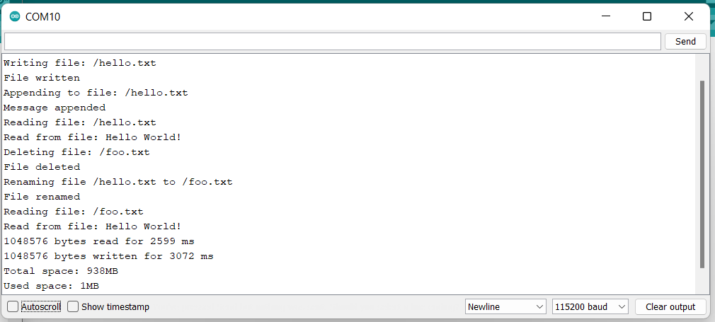
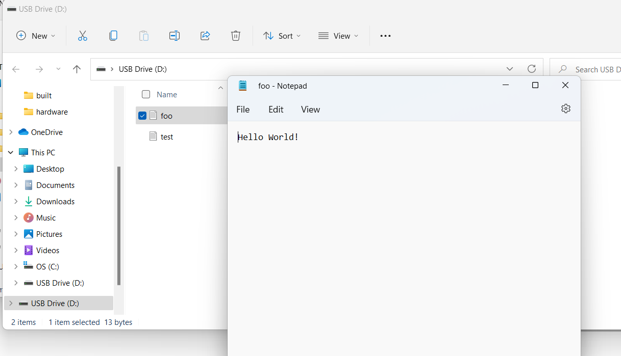
Data will spit out to files on your SD Card. When you read the card with an SD Card Reader, you should see a couple of sample files like these!
Example 4: I2C
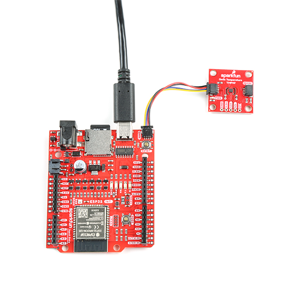
Our Qwiic Ecosystem is a fantastic way to add plug and play functionality to your board. For this example, we're going to use the SparkFun High Precision Temperature Sensor - TMP117 (Qwiic) to do some quick (Qwiic) temperature readings.
The hookup is a breeze - simply plug one end of a Qwiic cable into the TMP117 and the other end into your IoT RedBoard ESP32!
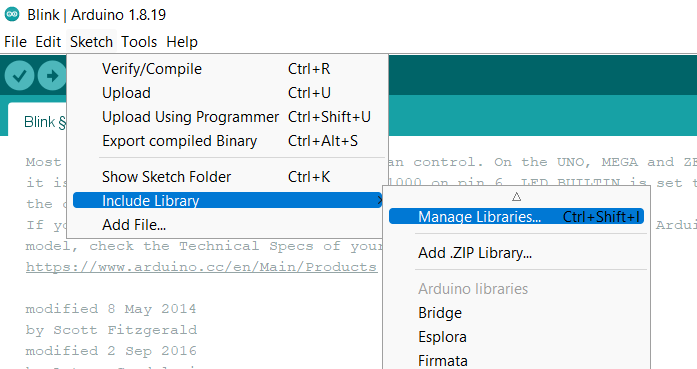
To find this example, you'll first need to install the Qwiic Library for whatever Qwiic Sensor you plan to use. For this example, go to Sketch > Include Library > Manage Libraries like so:
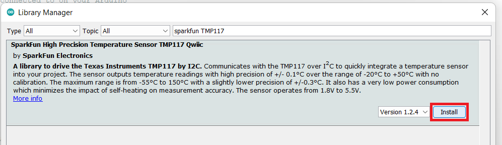
Search for SparkFun TMP117 in the window that comes up and install the library:
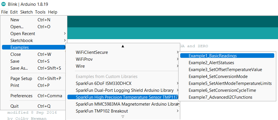
Great! Now that we have our library installed, we can run our example! Go to File > Examples > SparkFun High Precision Temperature Sensor TMP117 > Example1_BasicReadings.
Select the correct board and port, as always, and hit that upload button!
This particular example will check to see if the TMP117 measured and averaged the temperature readings. If there is data ready, the TMP117 will notify us from the configuration register. When ready, we'll read the temperature registers and output it out to the Arduino serial monitor.
Open the serial monitor at 115200 baud to start reading the temperature readings. You should see something like the output below.
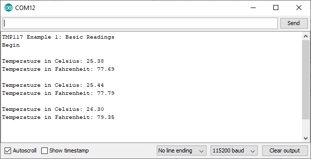
Try heating the sensor with your finger or lightly breathe some air across the sensor to watch the temperature values change! The third reading from the output shows the temperature rising after placing my finger on the temperature sensor. Remember, the sensor is taking a few readings and averaging them together before we are able see the output. Make sure to be patient with the output.
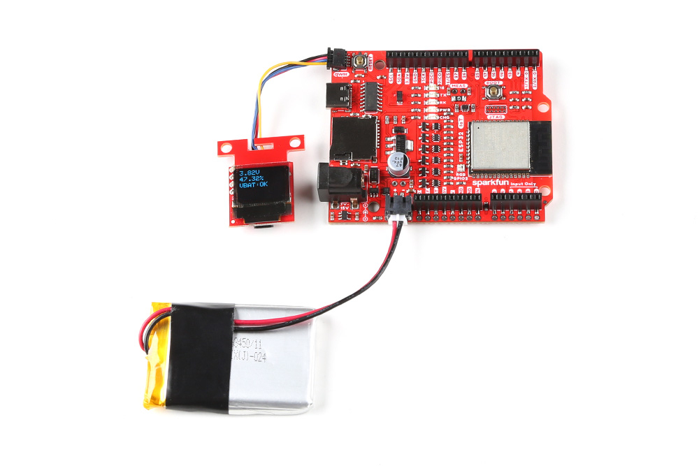
Example 5: LiPo Fuel Gauge - MAX17048
If you look closely at the board, there's also a built-in LiPo fuel guage to monitor your LiPo battery!
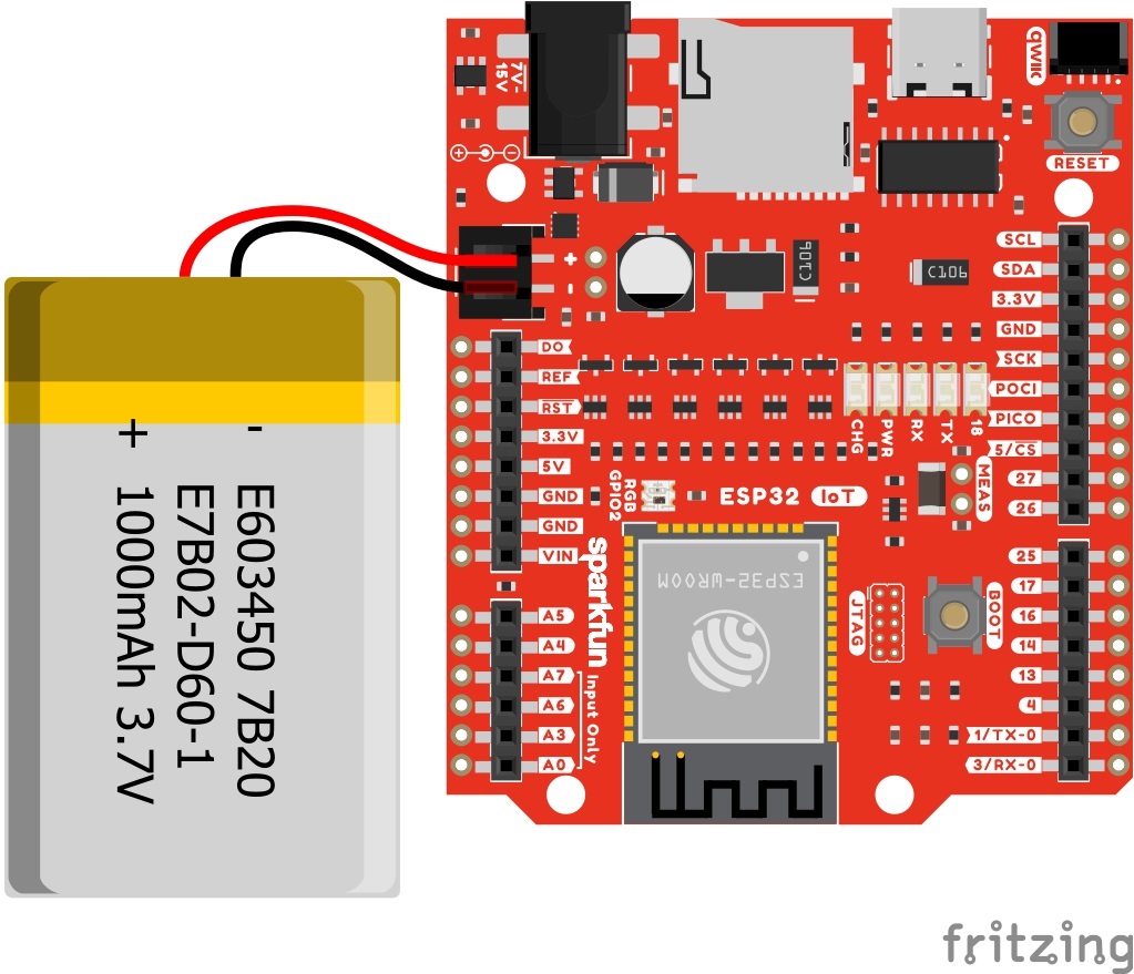
In this case, we did not need to solder anything! The IoT RedBoard - ESP32 has a built in LiPo Fuel Gauge (MAX17048). By simply connecting a LiPo battery to the 2-pin JST connector and uploading code, we should be good to go!
SparkFun MAX1704x Fuel Gauge Arduino Library
Just like the previous example, you will need to install the Arduino Library for the MAX17048.
The SparkFun MAX1704x Fuel Gauge Arduino Library can be downloaded with the Arduino library manager by searching 'SparkFun MAX1704x Fuel Gauge' or you can grab the zip here from the GitHub repository to manually install.
Example Code
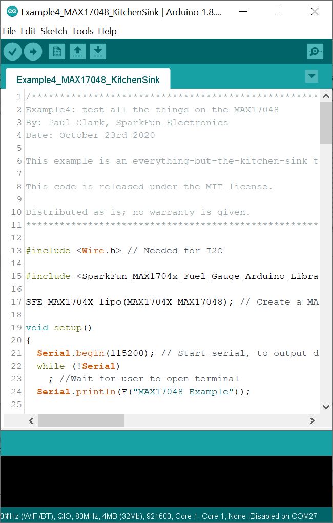
From the menu, select the following: File > Examples > SparkFun_MAX1704x_Fuel_Gauge_Arduino_Library > Example4_MAX17048_KitchenSink. If you have not already, select your Board (in this case the SparkFun ESP32 IoT RedBoard), and associated COM port (in this case COM27). Then hit the upload button.
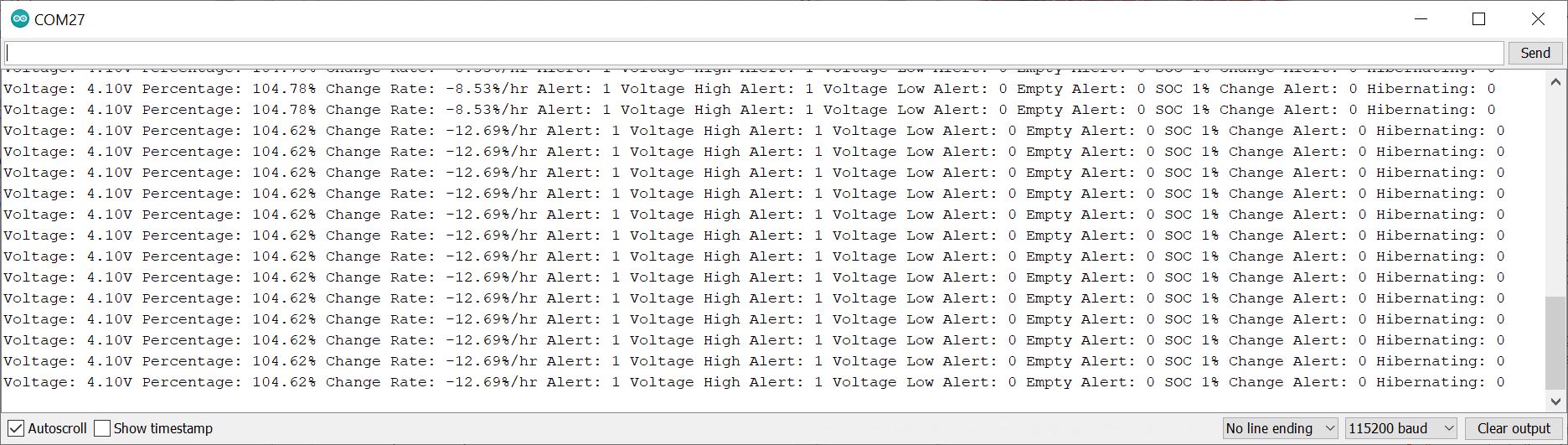
Open the Arduino Serial Monitor and set it to 115200 baud to view the serial output. You should see the voltage, battery percent, alert flag, and several more readings. In this case, the single cell LiPo battery that was connected to the IC was fully charged and at about 4.10V.
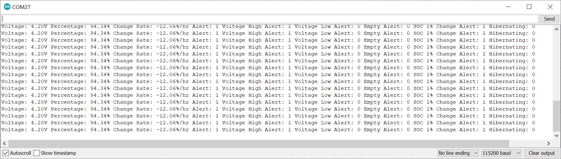
But wait! If you looked closely at the circuit of the SparkFun IoT RedBoard - ESP32 Development Board, there is also... a charge circuit built in. Try closing out the Arduino Serial Monitor, disconnecting the USB, and disconnecting the LiPo battery. Then reinsert the LiPo battery, connect the USB cable, and reopen the Arduino Serial Monitor. The IC will recalculate everything. In the image below, the voltage is a bit misleading since the charge IC is charging the LiPo battery and may not be the true representation of the LiPo battery's voltage. The remaining charge was closer to what was expected.
Troubleshooting
If your product is not working as you expected or you need technical assistance or information, head on over to the SparkFun Technical Assistance page for some initial troubleshooting.
If you don't find what you need there, the SparkFun Forums are a great place to find and ask for help. If this is your first visit, you'll need to create a Forum Account to search product forums and post questions.
Resources and Going Further
Now that you've successfully got your SparkFun IoT RedBoard ESP32 Development Board up and running, it's time to incorporate it into your own project!
For more information, check out the resources below:
- Schematic
- Eagle Files
- Board Dimensions
- GitHub Hardware Repo
- How to Install CH340C Drivers
- Fritzing Part
- Arduino Buying Guide
- Arduino IDE Download
- Qwiic Info Page
- Compare SparkFun RedBoards
Need some inspiration for your next project? Check out some of these related tutorials: