IoT RedBoard ESP32 Development Board Hookup Guide
Contributors:
Ell C,  SparkFro
SparkFro 
Example 1: Blink
The Blink example is a great benchmark to make sure you've got everything up and running correctly. You can find the example here:
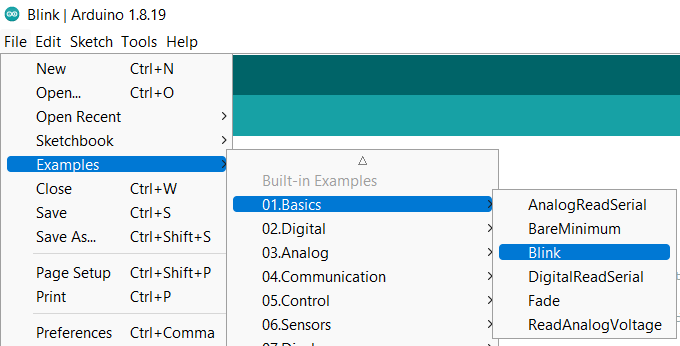
The LED pin is hard coded in this example, so you'll need to change it to pin 18. See the example code below if you need help:
language:c
/*
  Blink

  Turns an LED on for one second, then off for one second, repeatedly.

  Most Arduinos have an on-board LED you can control. On the UNO, MEGA and ZERO
  it is attached to digital pin 13, on MKR1000 on pin 6. LED_BUILTIN is set to
  the correct LED pin independent of which board is used.
  If you want to know what pin the on-board LED is connected to on your Arduino
  model, check the Technical Specs of your board at:
  https://www.arduino.cc/en/Main/Products

  modified 8 May 2014
  by Scott Fitzgerald
  modified 2 Sep 2016
  by Arturo Guadalupi
  modified 8 Sep 2016
  by Colby Newman

  This example code is in the public domain.

  https://www.arduino.cc/en/Tutorial/BuiltInExamples/Blink
*/

#define LED_BUILTIN 18

// the setup function runs once when you press reset or power the board
void setup() {
  // initialize digital pin LED_BUILTIN as an output.
  pinMode(LED_BUILTIN, OUTPUT);
}

// the loop function runs over and over again forever
void loop() {
  digitalWrite(LED_BUILTIN, HIGH);   // turn the LED on (HIGH is the voltage level)
  delay(1000);                       // wait for a second
  digitalWrite(LED_BUILTIN, LOW);    // turn the LED off by making the voltage LOW
  delay(1000);                       // wait for a second
}
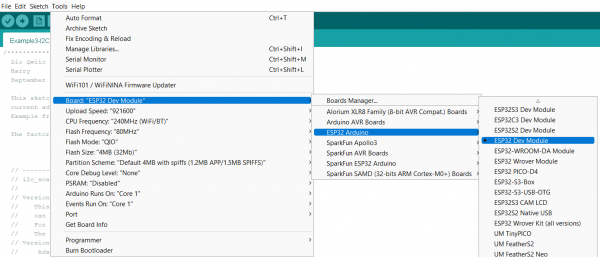
Make sure you have the correct Board Selected like so:
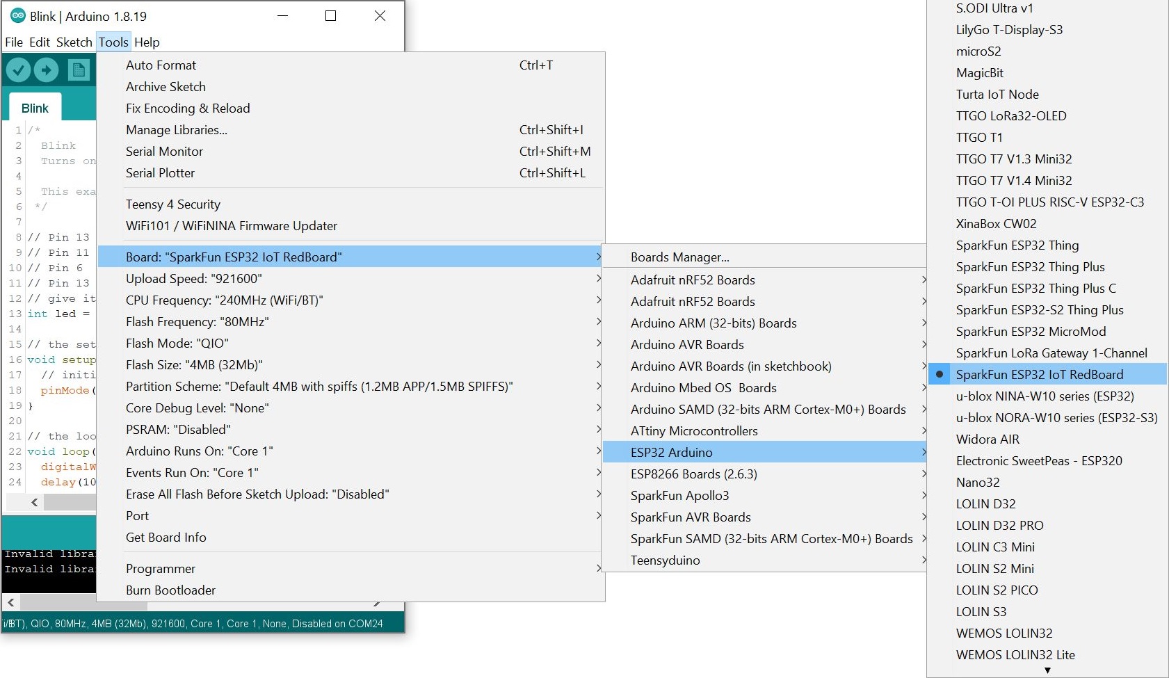
Note:: At the time of writing, the board definition was not added to espressif's ESP32's board package. Thus, the generic board definition was used: "ESP32 Dev Module". Both board definitions can work but we recommend using the SparkFun ESP32 IoT RedBoard.

Smash that upload button and if all goes well, you'll see LED 18 blink on and off!