Interactive 3D Printed LED Diamond Prop
 bboyho
Hardware Hookup
Non-Addressable RGB LED Strip
With some non-addressable RGB LED strips left over from a previous project, I decided to cut down the remaining strip and solder male jumper wire with male pins. To make it easier, you could use a 4-pin polarized connector and a 1M sealed strip. For the scope of this tutorial, we will be modifying the LED strip and using male jumper wires.
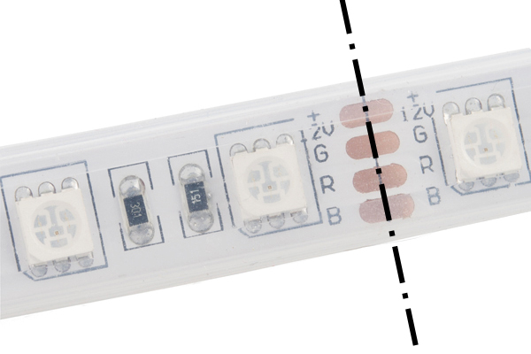
Cut the LED strip at the center of the exposed pads using a diagonal cutter. The dot and dashed line in the image below is where you will need to perform the cut. Make sure to remove part of the silicone tube in order to be able to access the LED strip's pads.
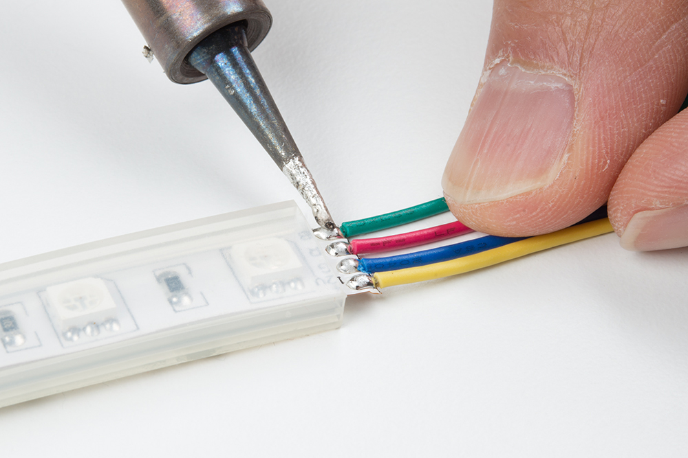
Cut half of the 12" premium jumper wires and strip the insulation. Then solder the wires to each of the LED strip's pads.
The connection to the pads needed to be secure so I decided to braid the wires together to manage the connections. I was inspired by McCall’s tutorial when completing projects. To braid your wires, twist a pair of wires in a counterclockwise pattern between your index finger and thumb using both hands. I decided to start with the green and red wires.
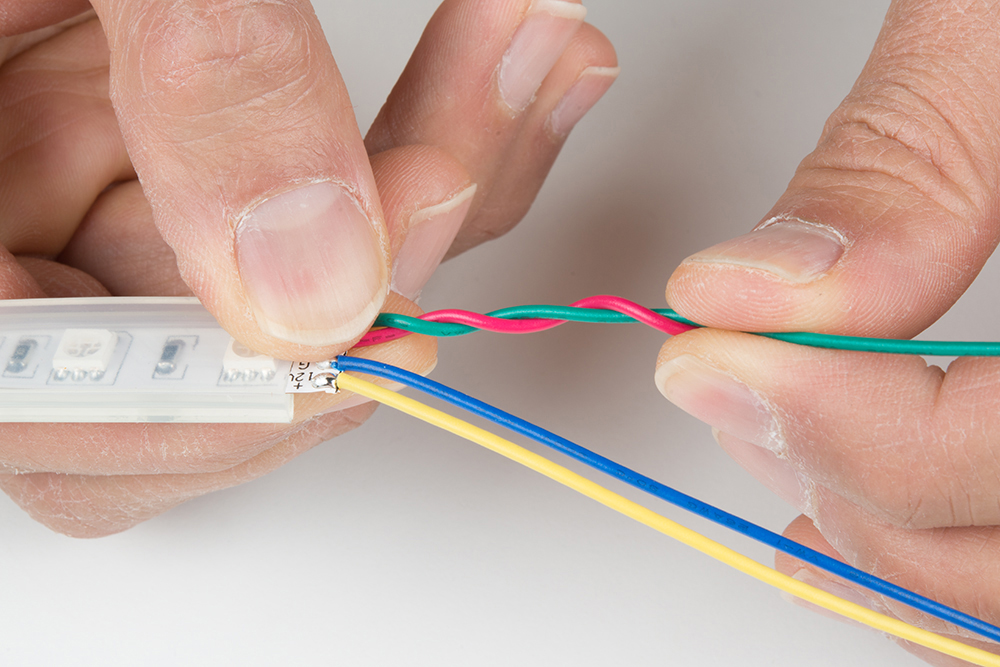
Twist the other pair of wires in a counterclockwise pattern.

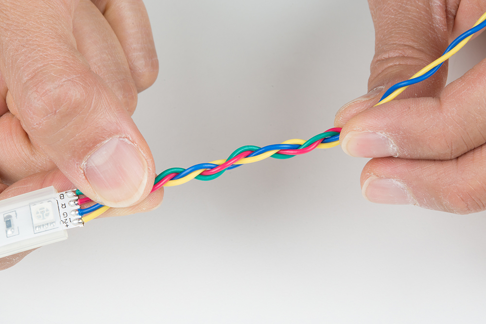
Twist the pairs of wires in a clockwise pattern.
Clean Solder Joints
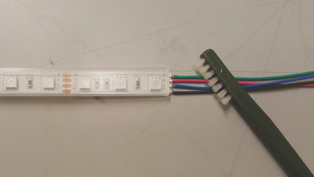
If you were using water soluble flux, clean the solder joints with de-ionized water and a toothbrush. Dry the LED strips thoroughly using compressed air. Luckily, SparkFun has a PCB cleaning room. As an alternative, you could use water from the sink and towels.
Test LED Strips
Once dry, test the LED strips to make the colors matched and the wires are connected to its respective pads. I decided to use a benchtop power supply set to output about 9V to verify the connection.
Secure w/ Hot Glue
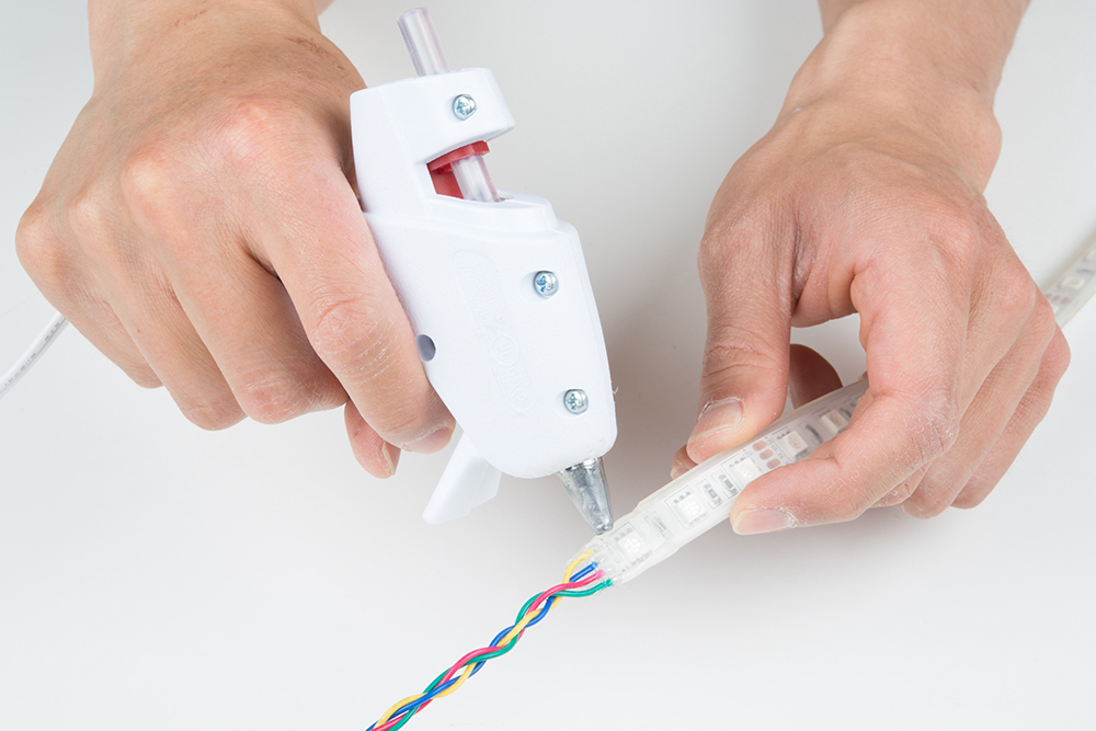
Add hot glue to the terminals to secure the wires further.
Custom LED Strip Adapter
I decided to use a spare XBee shield for the LED strip's adapter. This also gave me the option of making the circuit wireless if I were to use this in a future project. For the scope of this tutorial, we will be using the XBee shield. You could use a protoshield for more space.
To make the adapter, solder the three n-channel mosfets, three 10kΩ resistors, and two buttons to the prototyping area based on the Fritzing circuit shown earlier. The two solder jumpers were that were connected to the logic level converters and the associated pins were removed. With very little room left, wires were extended out of the bottom of the shield using female headers and prototyping board. Again, the board was clean and tested before moving further.
 |
Capacitive Touch Sensor and Transistor
Solder the AT42QT1011 capacitive touch breakout with the longer ends facing the component side. At this point, there was not a lot of room left on the board. Therefore, a mini-breadboard, jumper wires, npn transistor, and 330Ω resistor was need to connect it to the rest of the circuit for initial testing.
