Interactive 3D Printed LED Diamond Prop
 bboyho
 Introduction
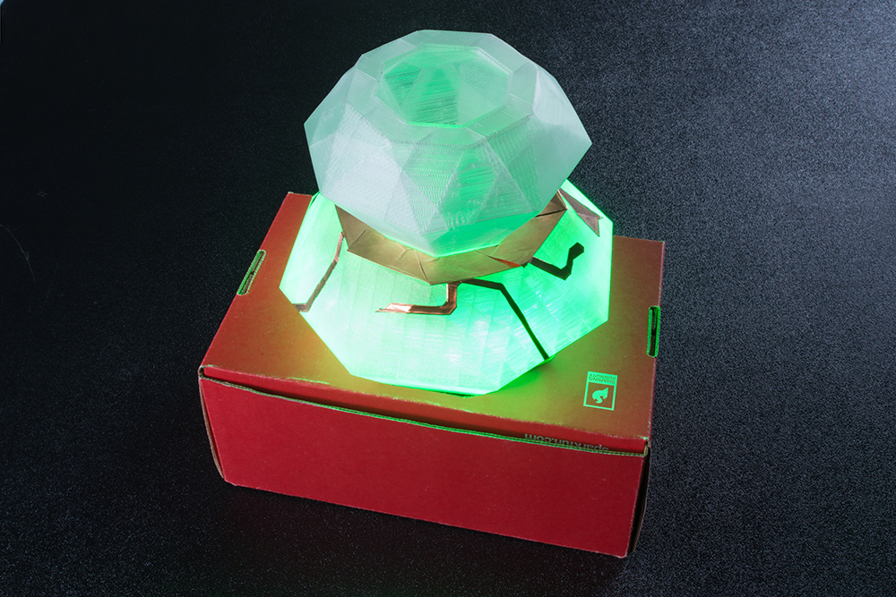
My students had a dance performance with the theme "Night at the Movies." I decided to choose a story based on "The Diamond" episode from the old Mission: Impossible television show. To make it fun for the kids and convey the story better to the audience, I decided to build an interactive 3D printed diamond. In this tutorial, you will learn how to 3D print a model and embed electronics in a theatrical prop.
Required Materials
To follow along with this project tutorial, you will need the following materials. You may not need everything though depending on what you have. Add it to your cart, read through the guide, and adjust the cart as necessary.
Tools
You will need a soldering tools, a 3D printer, and a hobby knife.


TAZ 6 3D Printer
TOL-13880
Weller WLC100 Soldering Station
TOL-14228You will also need:
- Scissors
- Electrical Tape
- Cutting Mat
- Transparent ABS 3mm Filament
Suggested Reading
If you aren't familiar with the following concepts, we recommend checking out these tutorials before continuing.
How to Power a Project
Installing Arduino IDE
Resistors
Transistors
AT42QT101X Capacitive Touch Breakout Hookup Guide
3D Print It
I do not have much experience with 3D printing and modeling complex shapes. Luckily, there were a few models of diamonds listed online that I found to save on time. After browsing Thingiverse, the model that I found appealing was "Oopee's" diamond lampshade. Head over to the thing and download to print the model of your size.
Printing a medium size diamond was sufficient and easy to see on stage as a prop. Caution is advised for printing large scale models due to time and material used.
A Small World, After All?
To start, I printed a small scale version of the diamond lampshade in Cura to see how it would look. The diamond on the bottom left shows the first print of the diamond against the larger prints. Satisfied with the small print. I decided to go bigger!

Big Trouble in Little... Nozzle
I decided to go big and start printing the diamond. Unfortunately, I ran into an issue once the print started. The 3D printer's extruder kept getting clogged causing the print to fail. I tried using a needle to clean the nozzle and manually feeding more material in the extruder. This fixed the problem temporarily but the issue kept coming up.
Doing a search online and inspecting the setup, there were a few possible reasons why this might have been happening:
- incorrect idler tension
- speed of the print
- poor quality filament
- filament tangled in spool
- clogged extruder
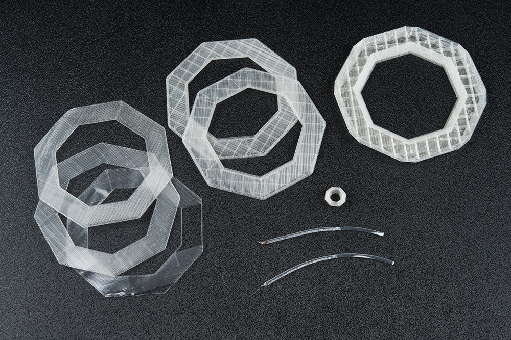
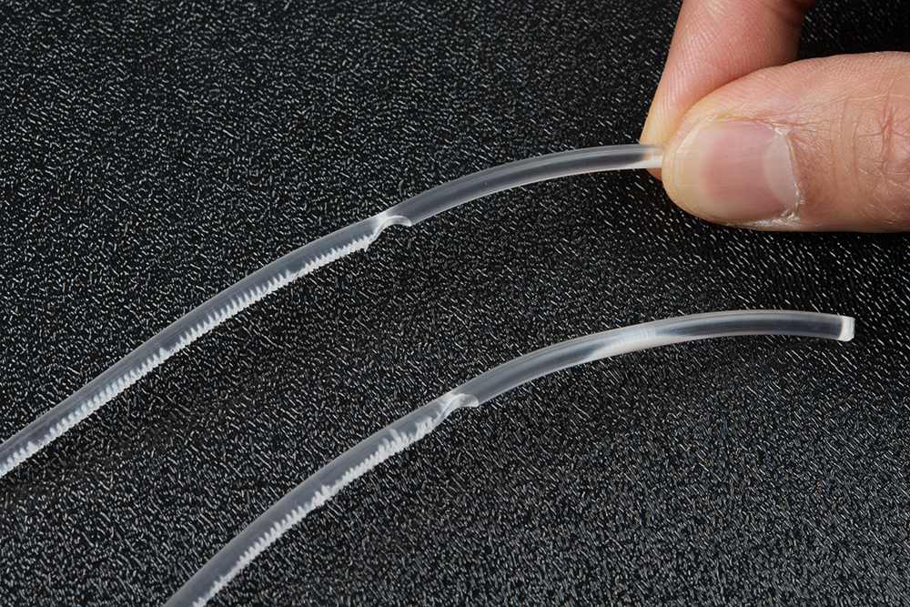
A clogged extruder seemed to be a plausible explanation of what was going on. Checking in with someone more knowledgeable about 3D printing at SparkFun, I headed over to a mechanical engineer for advice and showed him a few of the stripped filaments as shown below.
He was able to confirm my assumption. With the technical support's 3D printer being used communally, he explained that the clogged extruder was probably due to either:
- impurities from poor quality filament (as stated above)
- changing filament material (PLA to ABS)
Acetone Bath
So how would you fix the clogged extruder? An acetone bath! This was a last resort considering my previous efforts had failed. After removing the tool head from the Lulzbot 3D printer, we carefully removed the hot end's nozzle using some pliers. And by careful, we had to avoid breaking the thermistor attached to the hot end. Once removed, a glass jar was filled just enough to submerge the nozzle tip in acetone and cleaned with a Q-tip over the course of 2 days.
Insufficient Filament and Recycling a Failed Print
While the nozzle was being cleaned, our mechanical engineer was kind enough to allow me to use the mechanical engineering's 3D printer. Off I went to print the big diamond. However, I ran into yet another problem. I did not have enough material! I was too ambitious and did not keep track of the amount of material I had available. 30 hours into the print, I ran out of material as you can see from the image below. While the print failed, I decided to recycle the failed print by making it into a diamond holder.
A Happy Medium
Success! On my 10th attempt with a replenished supply of clear filament, I was able to successfully print a diamond. I found a happy medium of printing a diamond. After learning some lessons from the failed prints, I reduced the amount of material used between the walls and reduced the size of the model to a smaller size. Confident in the print, I printed another diamond slightly larger.
Understanding Your Circuit
Circuit Diagram
Check out the circuit diagram below to see how everything is connected.
Remote Power
During rehearsals, the prop was initially powered by a 12V wall adapter. It was bulky and not ideal for quick set changes between pieces. Therefore, I decided make it portable using a 9V battery to power the LED strip and controller.
After testing, I noticed that the 9V battery connected to the Arduino's microcontroller not sufficient enough for the LED strip. The LED strip was not bright enough or would display the wrong color.To remedy this, a second 9V battery was attached to the LED strip. Ground was connected to both batteries for reference.
Controlling the LEDs
Since the non-addressable RGB LED strip operate at a higher voltage, a transistor was needed to prevent damage to the microcontroller. A pull-down resistor was also needed so that the Arduino would not have a floating pin. Each color required one n-channel mosfet and one 10kΩ resistor.
Momentary Button to Capacitive Touch Sensing
Initial testing included momentary push buttons with code utilizing the pull-up resistors on the digital pins. One button (connected to pin 2 with a white wire) was used to adjust the color while the other (connected to pin 3 with a yellow wire) was used to change the pattern. The buttons were left on the board to troubleshoot connections.
Eventually, the button to trigger the color was replaced with a capacitive touch sensor and external electrodes. The Arduino had issues reading the capacitive touch sensor's "OUT" pin by itself so a small npn transistor was added to trigger the button press. A resistor was used as current limiting resistor to the BJT's base pin.
Hardware Hookup
Non-Addressable RGB LED Strip
With some non-addressable RGB LED strips left over from a previous project, I decided to cut down the remaining strip and solder male jumper wire with male pins. To make it easier, you could use a 4-pin polarized connector and a 1M sealed strip. For the scope of this tutorial, we will be modifying the LED strip and using male jumper wires.
Cut the LED strip at the center of the exposed pads using a diagonal cutter. The dot and dashed line in the image below is where you will need to perform the cut. Make sure to remove part of the silicone tube in order to be able to access the LED strip's pads.
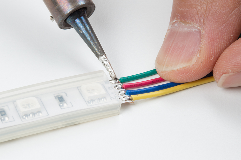
Cut half of the 12" premium jumper wires and strip the insulation. Then solder the wires to each of the LED strip's pads.
The connection to the pads needed to be secure so I decided to braid the wires together to manage the connections. I was inspired by McCall’s tutorial when completing projects. To braid your wires, twist a pair of wires in a counterclockwise pattern between your index finger and thumb using both hands. I decided to start with the green and red wires.
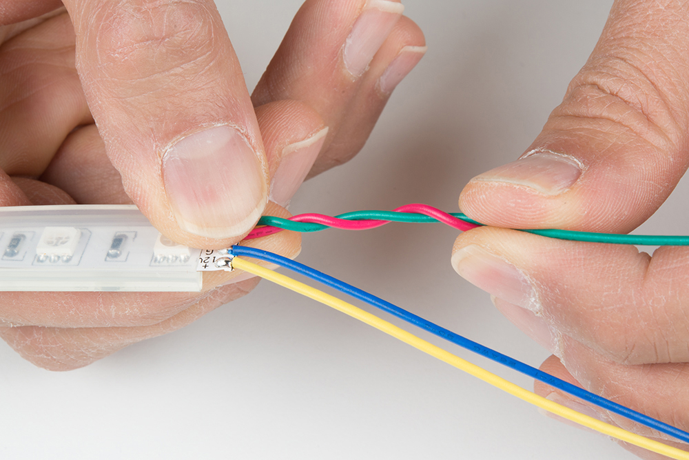
Twist the other pair of wires in a counterclockwise pattern.

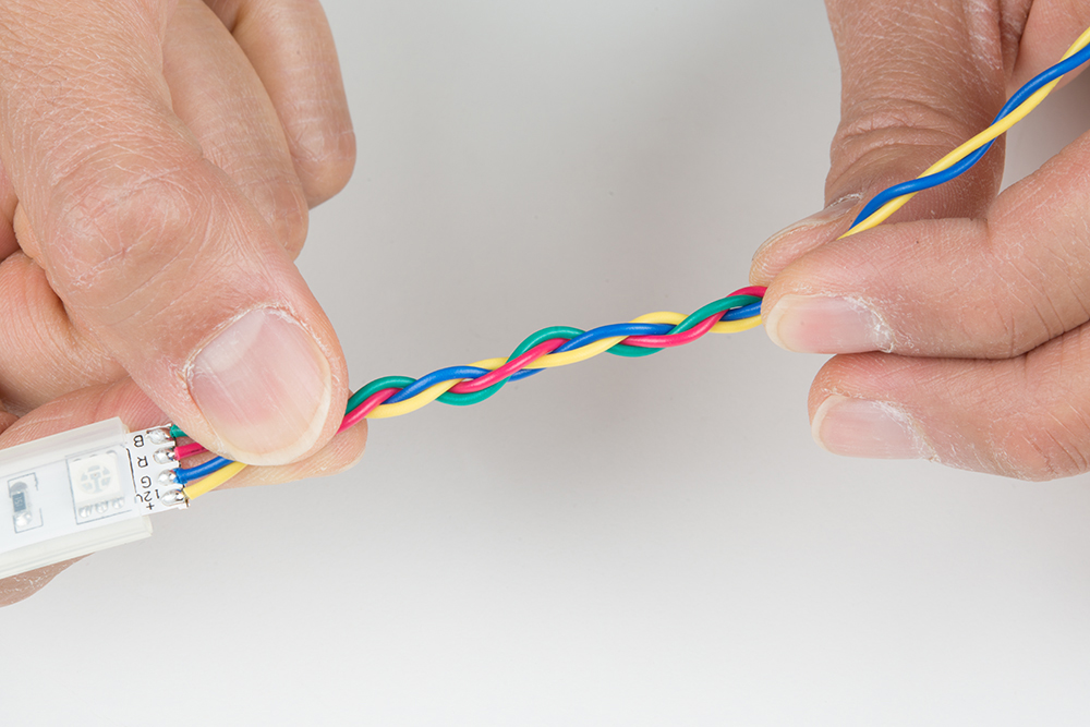
Twist the pairs of wires in a clockwise pattern.
Clean Solder Joints
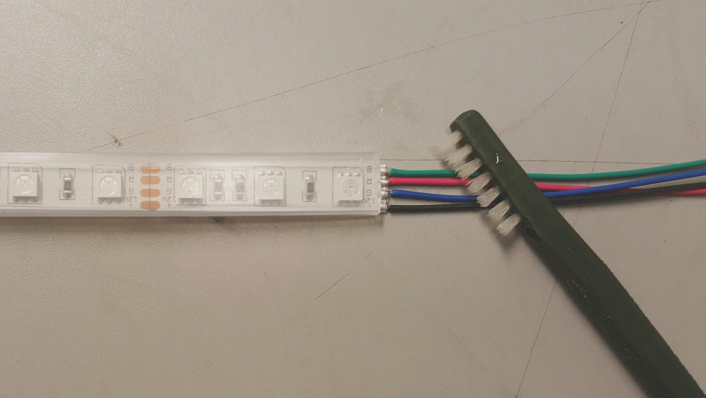
If you were using water soluble flux, clean the solder joints with de-ionized water and a toothbrush. Dry the LED strips thoroughly using compressed air. Luckily, SparkFun has a PCB cleaning room. As an alternative, you could use water from the sink and towels.
Test LED Strips
Once dry, test the LED strips to make the colors matched and the wires are connected to its respective pads. I decided to use a benchtop power supply set to output about 9V to verify the connection.
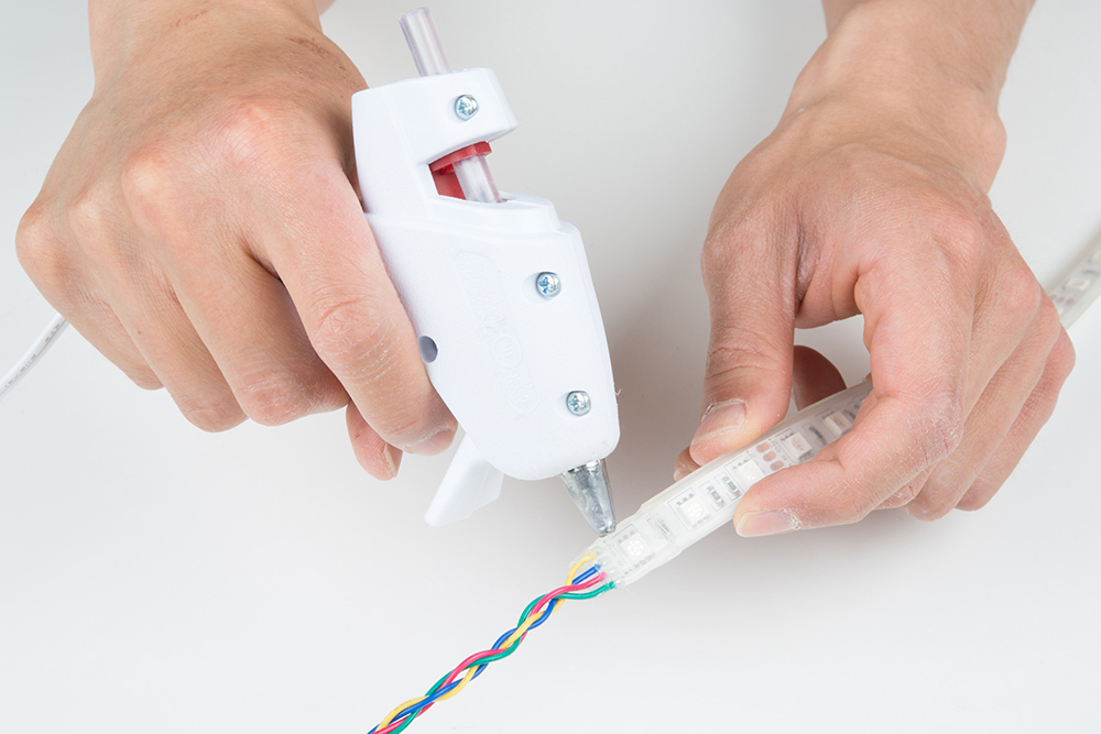
Secure w/ Hot Glue
Add hot glue to the terminals to secure the wires further.
Custom LED Strip Adapter
I decided to use a spare XBee shield for the LED strip's adapter. This also gave me the option of making the circuit wireless if I were to use this in a future project. For the scope of this tutorial, we will be using the XBee shield. You could use a protoshield for more space.
To make the adapter, solder the three n-channel mosfets, three 10kΩ resistors, and two buttons to the prototyping area based on the Fritzing circuit shown earlier. The two solder jumpers were that were connected to the logic level converters and the associated pins were removed. With very little room left, wires were extended out of the bottom of the shield using female headers and prototyping board. Again, the board was clean and tested before moving further.
 |
Capacitive Touch Sensor and Transistor
Solder the AT42QT1011 capacitive touch breakout with the longer ends facing the component side. At this point, there was not a lot of room left on the board. Therefore, a mini-breadboard, jumper wires, npn transistor, and 330Ω resistor was need to connect it to the rest of the circuit for initial testing.

Example Code
Note: This example assumes you are using the latest version of the Arduino IDE on your desktop. If this is your first time using Arduino, please review our tutorial on installing the Arduino IDE.
Download the example code to read the capacitive touch sensor and trigger the LED strip's color. Just make sure to select the correct COM port and upload with the correct board definition when uploading.
Enclosure
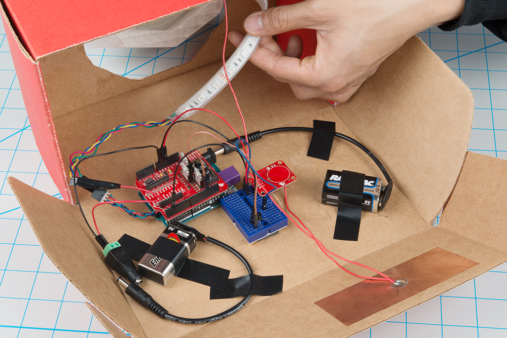
To secure the electronics, a cardboard enclosure was made to house the electronics. I considered using just the diamond holder but the space was limited. Grab a cardboard box and cut a hole in the shape of the holder's bottom.
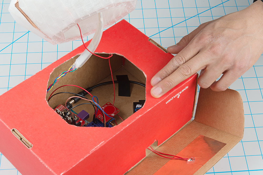
Placed the electronics in the enclosure and secure using electrical tape. This would also be a good time to tape the diamond holder down.
Cut an additional hole for the wires leading to the copper tape electrode.

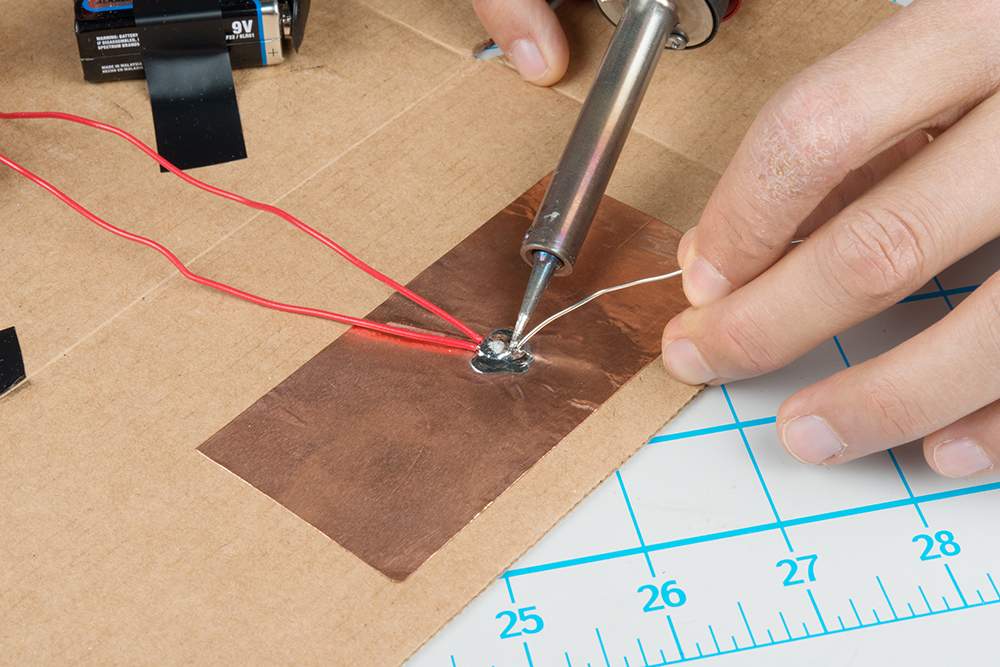
External Electrodes
Now that we have an enclosure, the finishing touches can be added to the prop. Cut out a strip of 2" copper tape and solder two pieces of wire to it. Make sure the wire is long enough to extend the capacitive touch sensor's pin labeled "PAD" to the circuit's enclosure and to the top of the diamond holder. Solder the other end of the wire to the capacitive touch sensor. Remove the backing and stick the copper tape to the inside wall of the enclosure.
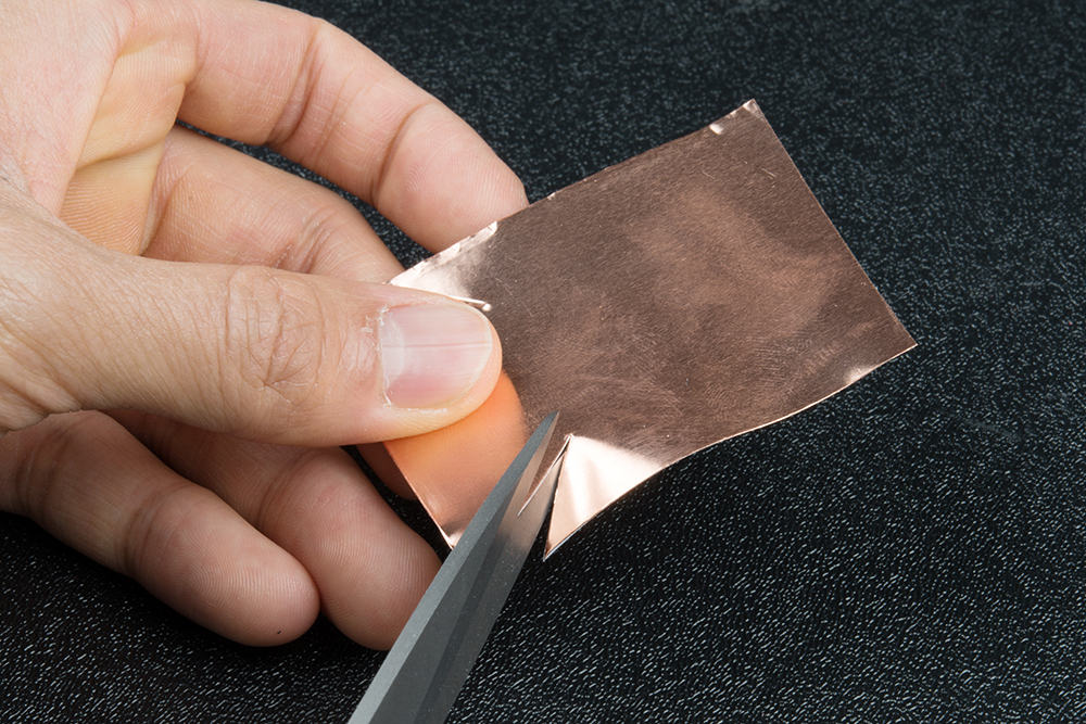
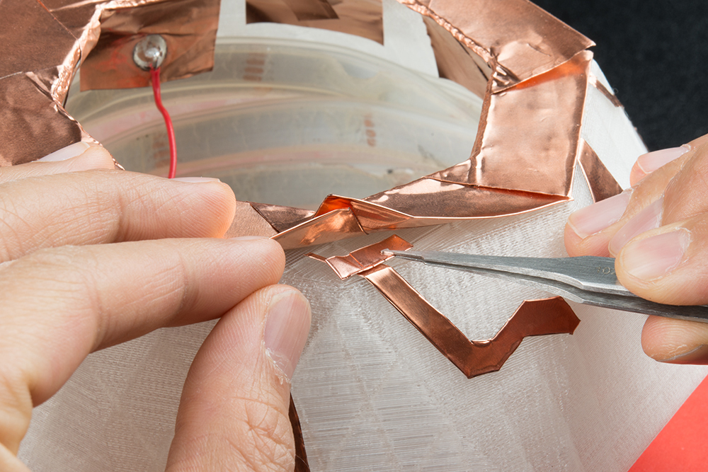
To distinguish the diamond and the holder, copper tape was also added to the top of the holder. Cut out a another piece of the 2" copper tape. Then cut into the tape to match the inside of the holder's edge.
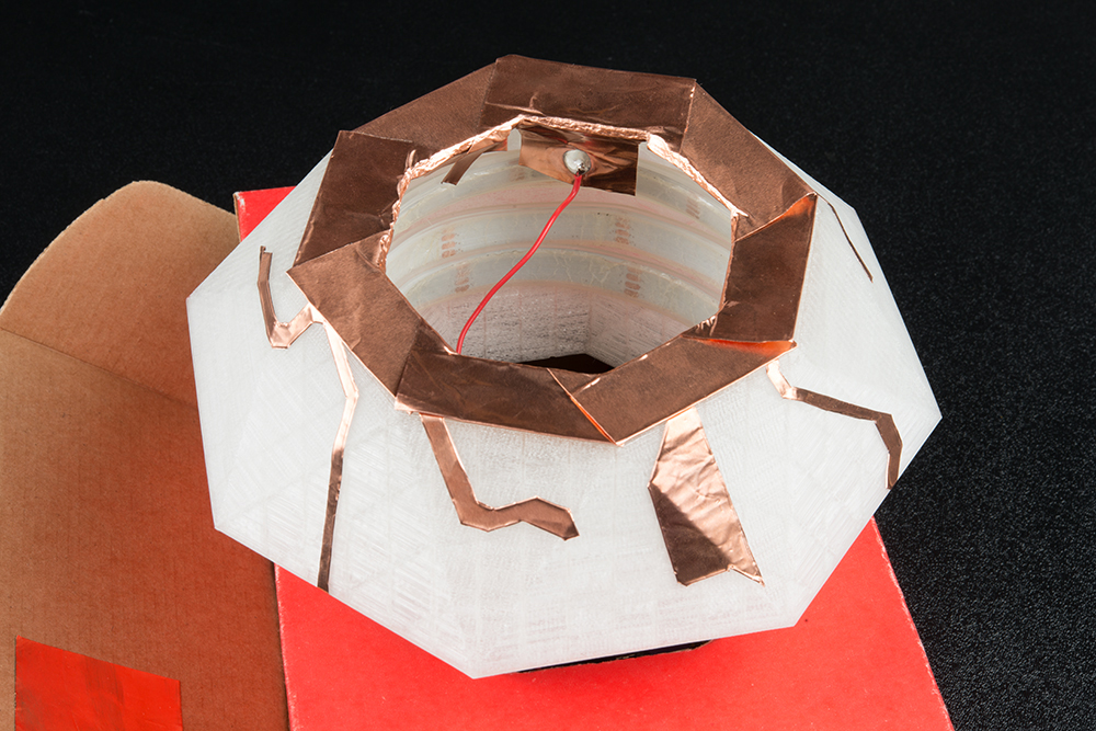
Remove the backing and attach the trapezoid section of the tape to the holder. Then fold the rest of the copper tape in half so that the conductive top side is able to conduct on the top and bottom. Then lay the copper tape flat. Repeat for each edge of the diamond until you have one side left.
 |
 |
With one side left, solder the second wire to extend the capacitive touch sensor's pad to the trapezoid section. Pull the wire up through the enclosure and holder. Attach the copper tape to the final edge.
Functional Art
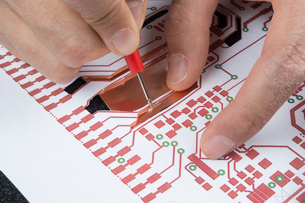
To blend the copper tape on the holder, I decided to add copper tape on the sides of a diamond. This is an optional step but it helped to distinguish the diamond's holder from the diamond itself. I decided to use the RedBoard's traces as a guide. Using the board layout files (with layers 16, 22, and 51 turned off), I was able to print out the top layer out. The angles from the traces helped as a guide when manually cutting. Manually cutting holes for vias was considered but was left out of the design.
Print out the file and cut out holes loosely based on the RedBoard's layout to make a stencil. Make sure that the traces are no less than 1/4 of an inch. Trace the outline with a semi-sharp tip. I used a multimeter prob tip to create a loose outline of the a few different traces.
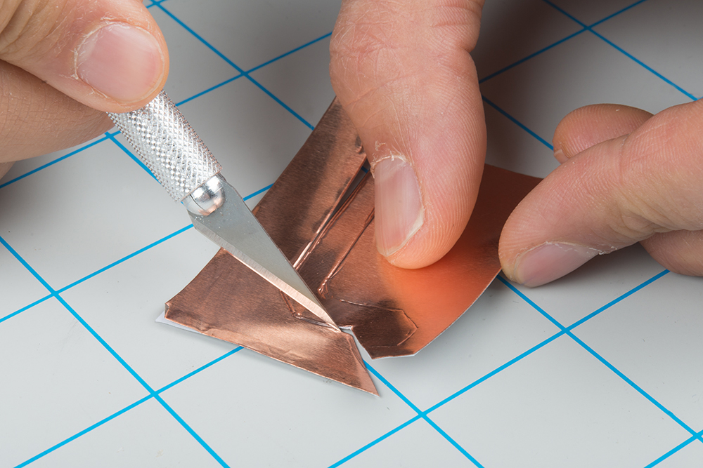
Carefully cut with hobby knife and ruler on a cutting board.
Using a small piece of 5mm conductive adhesive tape, I made a loop with the conductive adhesive on the outside and stuck it between each layer of copper to ensure that each piece was conducting.
Stress Testing in the Field
Arming the Diamond Prop
Here's a demo of how quickly I was able to power up and test the prop before the performance.
Triggering the Diamond Prop
There were a few methods of triggering the LED's color. My students were instructed to touch the top of the holder to trigger the red color in the middle of the piece. However, there were several other ways to change the color in case anything happened. Here's a quick demo.
Rehearsals
The instructions were simple enough for my students to understand and the circuit turned out well for the rehearsals.
 |
 |
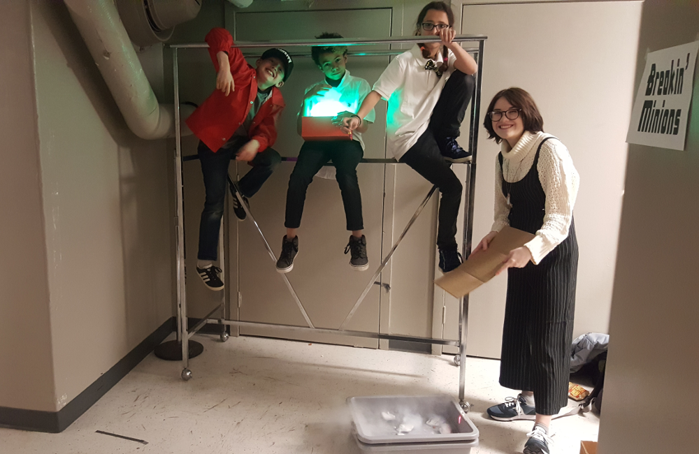
Show Time!
When it came time for the show, I had my handy multimeter, scissors, electrical tape, and backup 9V batteries just in case I needed to troubleshoot. However, the only issue that I ran into was not caused by the prop. The stage manager indicated that the fog from a fog machine could cause the fire alarm to go off. As an alternative, I found that dry ice and water seemed to work as a replacement. Here's a picture of the team after they went on!
Making It Better
There’s always room for improvement. After the project was completed, I realized that the prop could improved. Below are a list of possible upgrades and improvements that could be implemented for future builds.
- Conductive Adhesive 2" Copper Tape - Initially, I had regular copper tape in my parts bin. I did not realize there was a conductive adhesive until after the electrodes were attached to the diamond holder. Starting with the conductive adhesive 2" roll would have been better to start with.
- Jumper Wires - After soldering and taping copper tape to the enclosure, the wires seemed to be in the way when I needed to troubleshoot the circuit. Adding M/F jumper wires to connect and disconnect the capacitive touch sensor and enclosure would help make the project modular.
- Another Protoboard - To secure the connections better, I would have used another prototyping board (like the solderable bredabord to solder all the connections to a instead of having the capacitive touch sensor on a separate mini-breadboard.
- Switch - Opening the enclosure to plug in the batteries and then closing it was not too bad. Adding two latching power switches between the batteries would make it less tedious.
Resources and Going Further
For more information related to the project, check out the resources below:
- IMDB: Mission: Impossible The Diamond
- RedBoard v22 Top Layer (PDF)
- Thingiverse: Diamond Lampshade
- GitHub Code Repo
Need some inspiration for your next project? Check out some of these related tutorials:
Prototype Wearable LED Dance Harness
Vox Imperium: Stormtrooper Voice Changer
TeensyView Hookup Guide
3D Printed Illuminated Wand Prop
Or check out some of these blog posts for ideas: