3D Printed Illuminated Wand Prop
Introduction
In this tutorial, we will learn about how to create a theatrical prop for a performance by 3D printing a wand and adding an LED.
Required Materials
To follow along with this project tutorial, you will need the following materials. You may not need everything though depending on what you have. Add it to your cart, read through the guide, and adjust the cart as necessary.
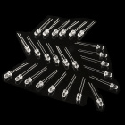
LED - Super Bright White (25 pack)
COM-09850Tools
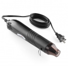
You will need a soldering tools, a 3D printer, and ABS filament. A heat gun or hot air rework station is optional for applying heat to heat shrink or if you want to smooth out the edges of hot glue.
ABS Filament 3mm - 1kg (Black)
TOL-12954TAZ 6 3D Printer
TOL-13880Wire Strippers - 20-30AWG
TOL-14763You will also need:
- Scissors
- Hot Glue Gun and Glue Sticks
- Sand Paper or Filer
Suggested Reading
If you aren't familiar with the following concepts, we recommend checking out these tutorials before continuing. The flashlight kit is a good beginning kit to start with if you have not soldered before!
How to Power a Project
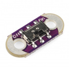
LilyPad Buttons and Switches
Flashlight Kit
3D Print it
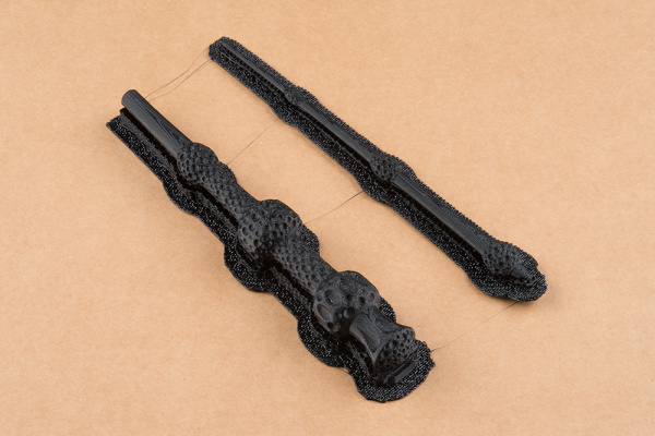
After browsing Thingiverse, the model that I found appealing was “jakereeves” elder wand. Head over to the thing and download the files to print the model of your size. Since the print area is small, you will need to print the part in two pieces.
Understanding Your Circuit
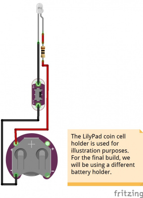
The circuit is simple and consists of an LED, 10Ω resistor, LilyPad switch, and a battery holder. I chose to add a current limiting resistor between the anode (longer leg) of the LED and "+" terminal of the battery holder. The resistor was probably not necessary since a coin cell is not able to source enough current to damage the LED. Nonetheless, a resistor was still added as good practice. The LilyPad switch was added between the cathode (shorter leg) of the LED and the "--" terminal of the battery holder.
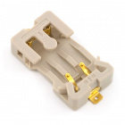
While the orientation of the switch did not affect the overall functionality of the circuit, I did decided to have the ON side of the LilyPad switch facing toward the LED for the user. Also, the LilyPad coin cell holder was a bit big compared to the size of the wand so a smaller holder was chosen for the project. There will be markings on the holder to indicate the "+" and "--" terminals with the alternative holder.
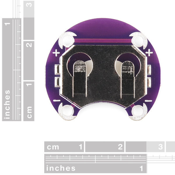 |
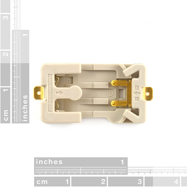 |
| Dimension of LilyPad Coin Cell Holder [PRT-10730] |
Dimension of Coin Cell Holder [DEV-08822] |
Hardware Hookup
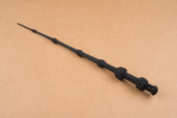
After printing the wand on your 3D printer and removing it from the print area, you will need to remove the raft support under the wand. Carefully remove support using pliers. With my settings, there was also some support printed in the handle that needed to be removed before gluing the two pieces together. When ready, add some hot glue in the dimple of the handle and join the two pieces together.
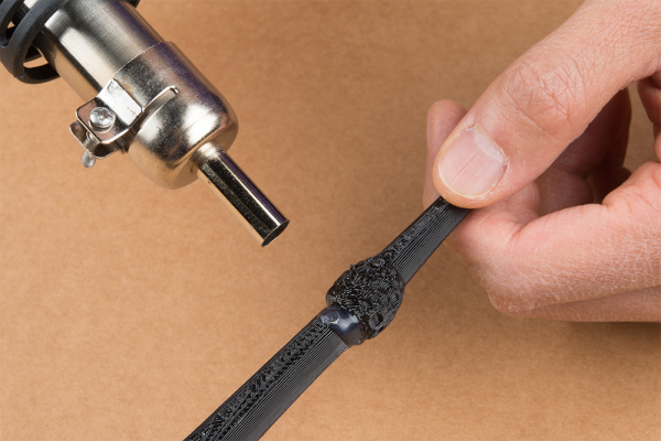
Once assembled, your wand should look similar to the image below.
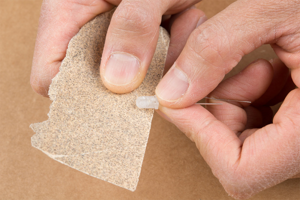
Let's start on the electronics side of the wand. The super bright white LED was bright but hard to see from all angles. To diffuse the LED and increase the viewing angle of the LED, you will need to sand the epoxy lens. Using sand paper or file, sand the outside of the LED. Make sure to hold the legs close to the LED to avoid damaging pins coming out of the epoxy lens.
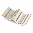
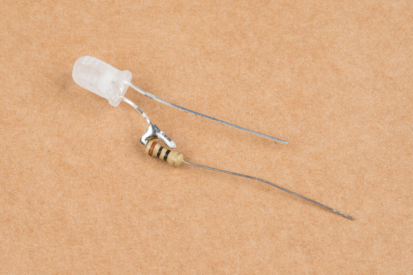
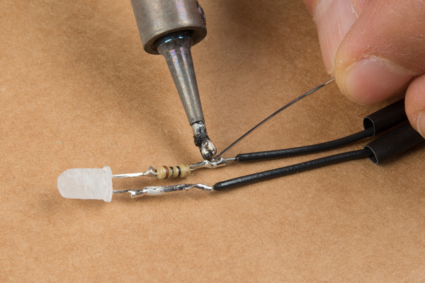
Wrap a current limiting resistor around one terminal of the LED. In this case, I added a 10Ω resistor to the longer leg of the LED (i.e. +, anode side). Then solder and trim down the remaining terminal with a flush cutter. Make sure to be careful when handling the resistor terminals since they are thin compared to the terminals of the LED.
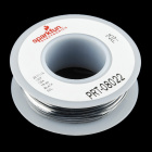
Cut two solid core wires so that they are able to run along the length of the wand. You will want a little extra room to work with the wire. Strip the wire ends and solder one wire to the shorter leg of the LED (i.e. --, cathode side). Then solder the second wire to the other end of the resistor.
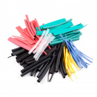
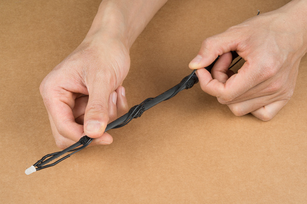
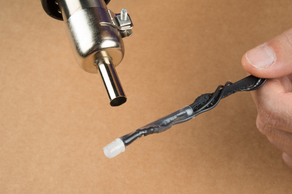
Cut some heat shrink to cover the exposed terminals of the LED and resistor. Slide the heat shrink down the wires and over the terminals. Wrap the wires around the wand. You will need to use one hand to hold the wires down as you twist the wires around the wand. Make sure the the wires are secure to the wand. If you are satisfied with the length of wires provided for the switch and coin cell holder's "+" terminal, apply heat to the heat shrink.
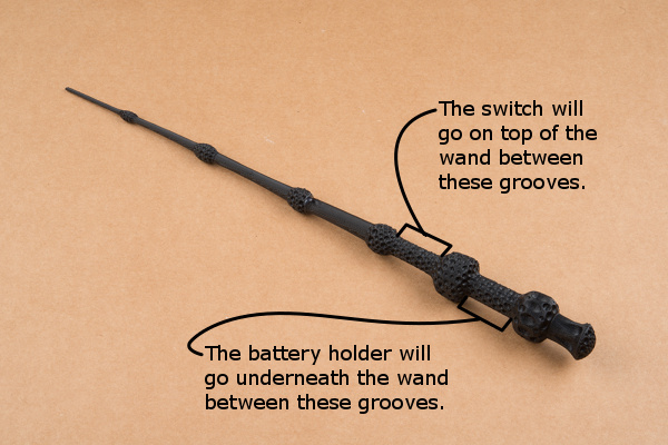
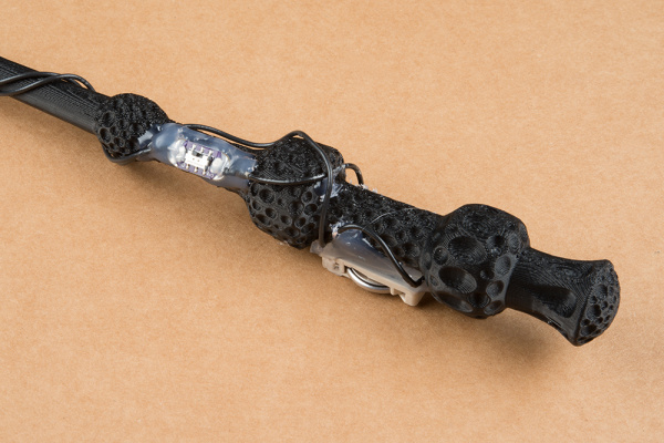
Before soldering wires to the switch and the coin cell battery holder, take note of the location of where the components will be added. The switch will go on the top of the wand between grooves shown in the image below. The battery holder will go underneath the wand (where the raft support was removed) between the grooves as shown in the image.
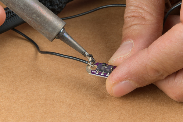
You should have enough wire to add a switch and battery holder. Solder the wire that was from the LED's cathode side (i.e. "-", longer leg) to the terminal adjacent to the ON position. If you are unsure of the polarity, test it out with a coin cell battery or multimeter.
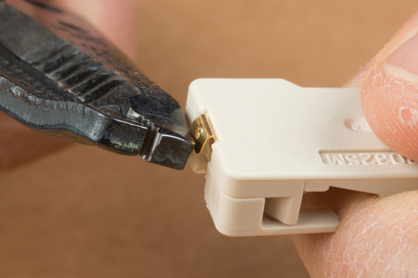
Carefully bend the terminals of the coin cell holder using the end of a wire stripper so that it can fit nicely between the grooves of the wand.
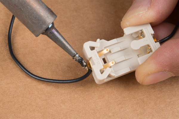
Strip the other end of the wire that is connected to the resistor and slide the exposed ends of the wire through the top of the "+" terminal's through hole. If you are satisfied with the length, solder the wire to the terminal. Then cut and strip another piece of wire to add between the switch's OFF position and the holder's "--" terminal.
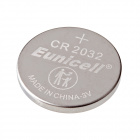
At this point, test out the connections with a coin cell battery or multimeter. Make sure the switch is flipped to the ON position. If you are using a coin cell battery, the battery does not need to be fully inserted in the coin cell holder to light up.
Cut some clear heat shrink and slide it over the LED and wand's tip. Apply heat to the heat shrink.
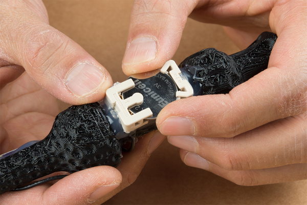
If you are satisfied with the connections, hot glue the bottom of the switch and coin cell battery holder to the wand. Avoid adding too much hot glue on the coin cell battery holder. If the holder's contacts to the battery are covered, it can interfere with the circuit causing the LED to not light up. Once the hot glue has cooled down, fully insert the coin cell battery into the holder.
The wand's handle should look similar to the image below.
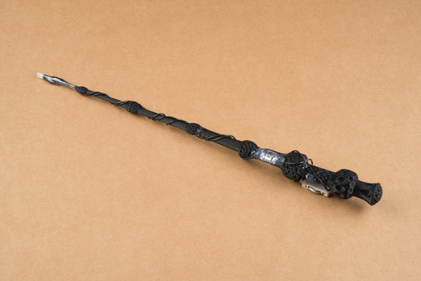
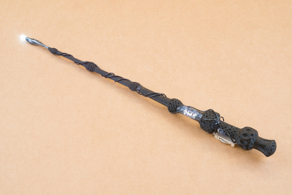
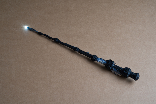
Your fully assembled 3D printed illuminated wand should look similar to the image below!
If you have not already, flip the switch to power the LED. Even in a bright room, the diffused LED was still visible!
 |
 |
| Illuminated Wand in Bright Room | Illuminated Wand in Low Light |
Repeat the steps above to make more wands as necessary for all of your wizards!
Stress Testing in the Field
Rehearsals
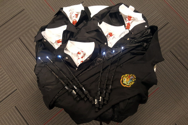
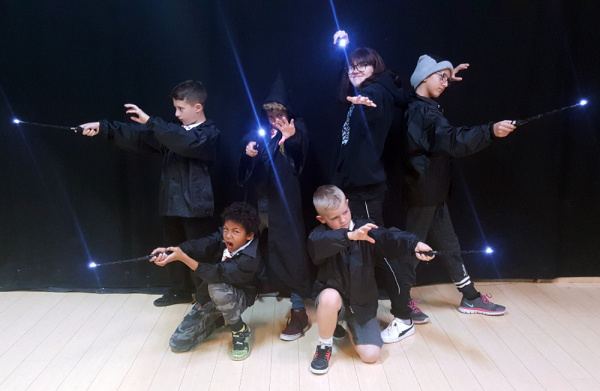
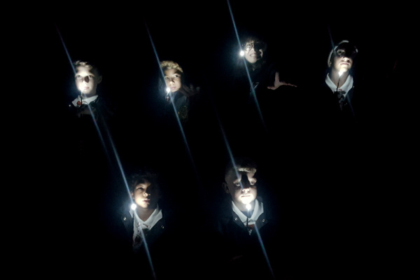
How did it go when I handed the illuminated wands over to my students? Well, they did not mind the circuit being wrapped around on the outside of the wand. The kids started saying magical incantations, ran around flicking imaginary balls of energy, and tried making things levitate. As a result, NO ONE WAS FOCUSED. Luckily, I handed them their illuminated wands during their last rehearsal before the fall show. At least they were really in character?
 |
 |
Show Time!
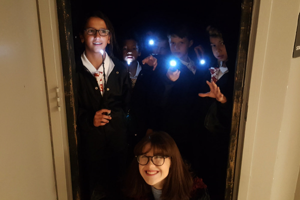
When it came time for the show, everything went as planned. The illuminated wands lasted throughout tech, during the performance, and after the show. Here’s a picture of the team after they went on!
Making it Better
There’s always room for improvement. After the project was completed, I had a few ideas of making the prop more functional. Below are a list of possible upgrades and improvements that could be implemented for future builds.
- Microcontroller and Sensors -- If I had more time, I would have wanted to add a microcontroller and sensors (i.e. an accelerometer and gyro) to each of the wands so that the LED would only turn on based on the gestures.
- Custom 3D Model -- I would have also wanted to design a wand from scratch to include the electronics on the inside similar to the other models found on Thingiverse.
Resources and Going Further
For more information related to the project, check out the resources below:
Need some inspiration for your next project? Check out some of these related tutorials:
Prototype Wearable LED Dance Harness
Vox Imperium: Stormtrooper Voice Changer
TeensyView Hookup Guide
Interactive 3D Printed LED Diamond Prop
Or check out some of these blog posts for ideas:
