Graphic LCD Hookup Guide
 jimblom
Hardware Assembly & Hookup
Before we get to uploading code and sending data to the display, let's take care of the hardware stuff first. That includes assembling the display, and hooking it up to the Arduino.
Assembly
To "assemble" the LCD, you'll need to solder something to one (or both) of the 8-pin headers. There are plenty of options available here. To make the LCD breadboard-compatible, straight or right-angle male headers can be soldered in.
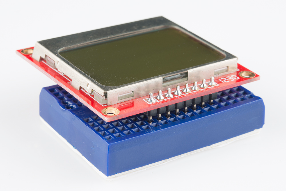
Otherwise, wires or other connectors can be soldered to the display pins.
Hookup
In this example we'll be connecting the LCD up to an Arduino, but this hookup should be easily adaptable to other development platforms. For the data transmission pins -- SCLK and DN(MOSI) -- we'll use the Arduino's hardware SPI pins, which will help to achieve a faster data transfer. The chip select (SCE), reset (RST), and a data/command (D/C) pins can be connected to any digital I/O pin. Finally, the LED pin should be connected to a PWM-capable Arduino pin, so we can dim the backlight as we please.
Unfortunately, the LCD has a maximum input voltage of 3.6V, so we can't hook up a standard 5V Arduino straight to it. We need to shift levels. This leads us to a few options for hookup:
Direct Connect
The easiest hookup is to connect the Arduino pins directly to the LCD. To allow for this easy hookup, you'll need a 3.3V-operating Arduino like the 3.3V/8MHz Pro or 3.3V Pro Mini.
This setup can work for 5V Arduino's, ignoring the 3.6V limit on the VCC and data lines. We've done this. It works. But it may decrease your LCD's life.
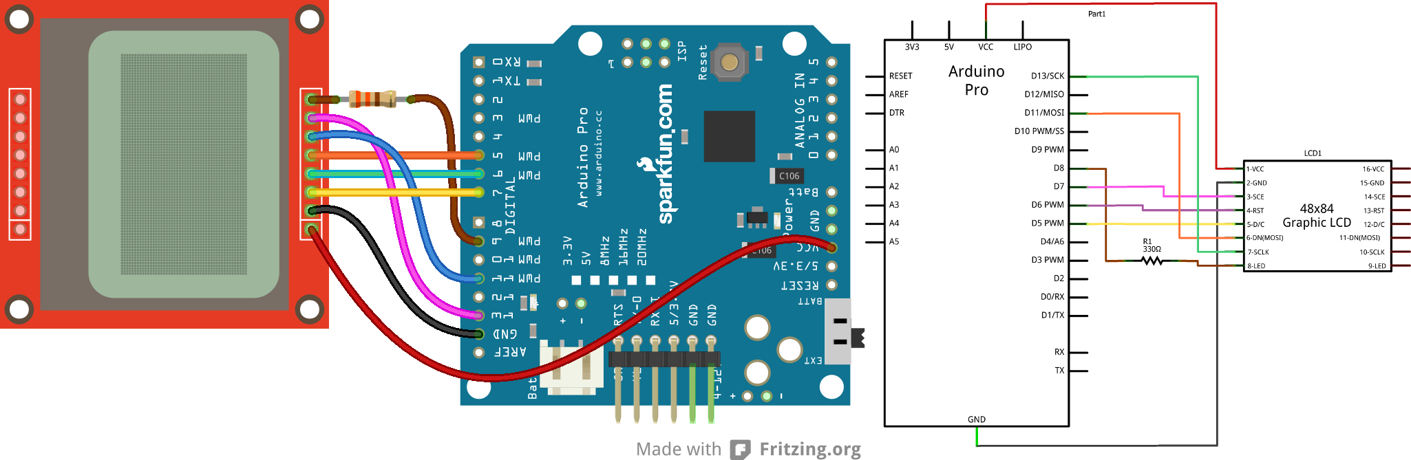
The data pins are connected as follows:
| LCD Pin | Arduino Pin | Notes |
|---|---|---|
| 1 - VCC | 3.3V (VCC) | 3.3V only (not 5V!) |
| 2 - GND | GND | |
| 3 - SCE | 7 | Can be any digital pin. |
| 4 - RST | 6 | Can be any digital pin. |
| 5 - D/C | 5 | Can be any digital pin. |
| 6 - DN(MOSI) | 11 | Can't be moved. |
| SCLK | 13 | Can't be moved. |
| LED | 9 | Can be any PWM pin. 330Ω resistor in between the pins. |
Limiting Resistors
Sticking resistors in-line with the data signals is a cheap, and easy way to add some protection to the 3.3V lines. If you have an Arduino Uno (or similar 5V 'duino) and some 10kΩ and 1kΩ resistors lying around, try this:
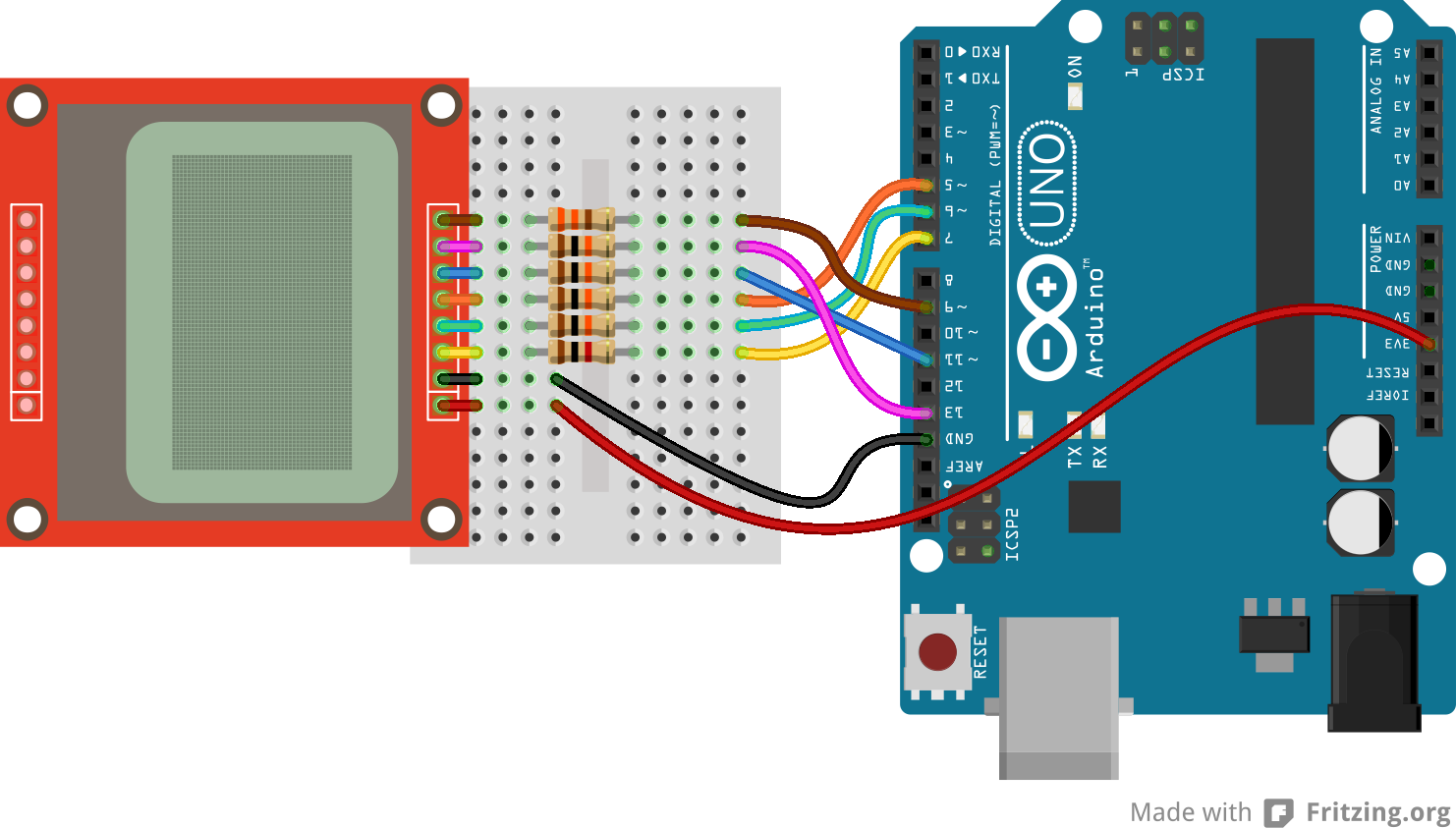
The pins are connected the same as in the above example, however each signal has an inline resistor. There are 10kΩ resistors between the SCLK, DN, D/C, and RST pins. A 1kΩ resistor between SCE and pin 7. And the 330Ω resistor remains between pin 9 and the LED pin.
Level Converters
Finally, a third option for hookup is to use actual level converters to switch between 5V and 3.3V. Boards like the Bi-Directional Logic Level Converter and the TXB0104 are perfect for something like this.
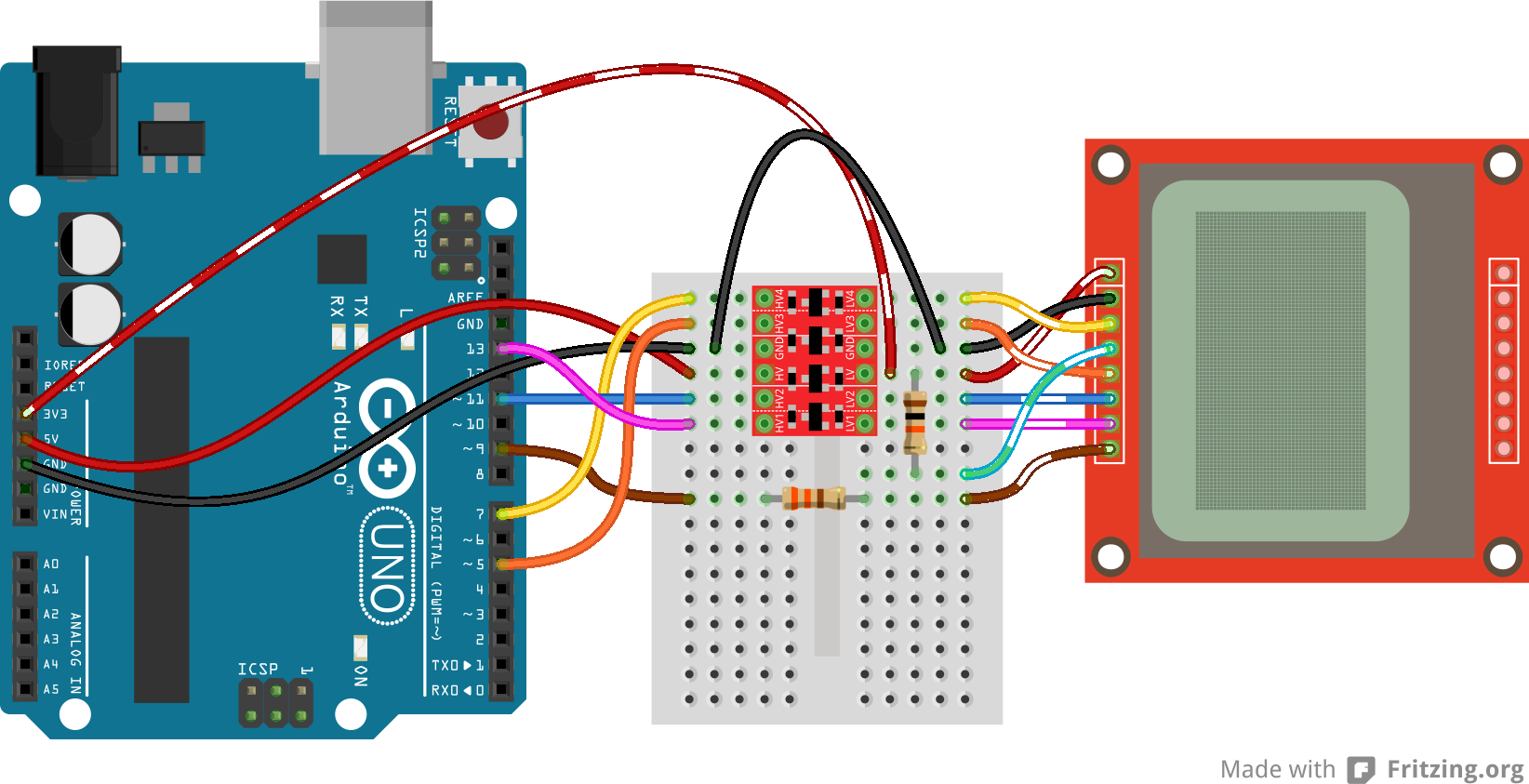
Unfortunately, the LCD has five 3.3V signal inputs and the level shifters only have four channels. If you want to keep the circuit to a single shifter, you can permanently tie RST high (through a 10kΩ resistors), and run the other signals through the shifter. You lose remote reset capability, but the rest of the control remains.
Check out the hook up guides for those boards for more help in shifting the signal between Arduino and LCD.