Graphic LCD Hookup Guide
 jimblom
Display Overview
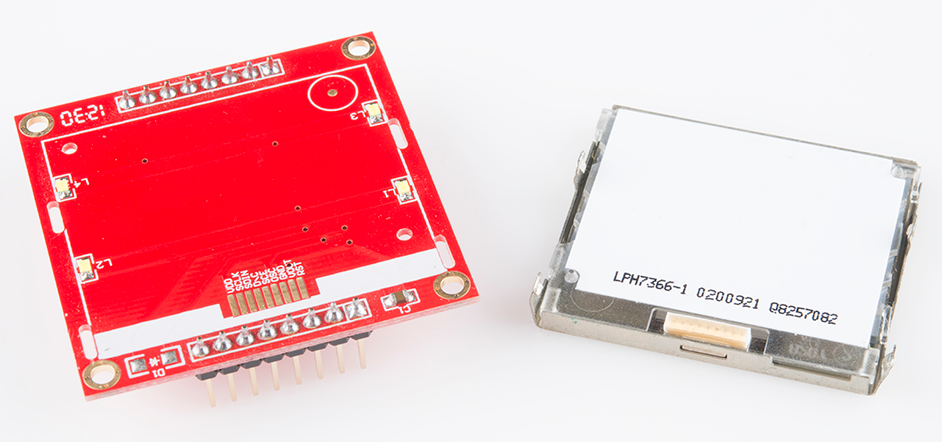
Before diving into hookup and example code, let's first take a look at the LCD and its breakout board. On this page we'll cover everything from the pinout of the board to the interface used to control the display.
The Pinout
To interface with and power the graphic LCD, there are two, parallel 8-pin headers above and below it. Flipping the board over, you'll find the labels for each of the pins.
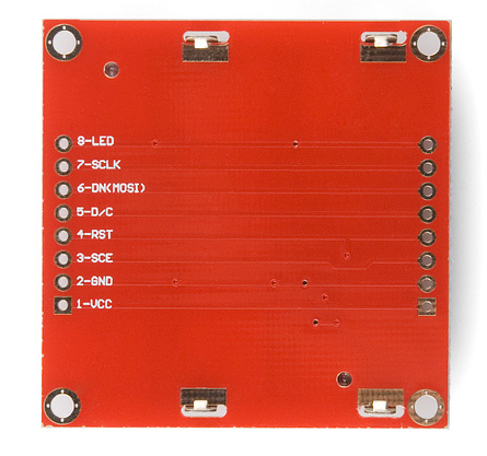
As you may be able to tell by the faint traces connecting them, each pin on one header is connected to the parallel pin on the other side. Here are the eight unique pins along with an overview of their purpose:
| Pin Number | Pin Label | Pin Function | Input/Output? | Notes |
|---|---|---|---|---|
| 1 | VCC | Positive power supply | Input | Supply range is between 2.7V and 3.3V |
| 2 | GND | Ground | Input | |
| 3 | SCE | Chip select | Input | Active low |
| 4 | RST | Reset | Input | Active low |
| 5 | D/C | Mode select | Input | Select between command mode (low) and data mode (high). |
| 6 | DN(MOSI) | Serial data in | Input | |
| 7 | SCLK | Serial clock | Input | |
| 8 | LED | LED backlight supply | Input | Maximum voltage supply is 3.3V. |
Power Supplies
There are two different supply voltages on the LCD. The most important supply voltage -- VCC -- supplies the logic circuits inside the LCD. The datasheet states this should be between 2.7 and 3.3V. In a normal state, the LCD will consume about 6 or 7mA.
The second voltage supply is required for the LED backlights on the board. If you were to remove the LCD from the PCB (not that you should, or need to), you'd see that these are backlights in their simplest form -- four white LEDs spaced around the edges of the board. You may also notice that there aren't any current limiting resistors.
This means you have to be careful with this voltage supply. Either stick a current limiting resistor in series with the 'LED' pin, or limit the supply to 3.3V max. The LEDs can pull a lot of current! With nothing to limit them, they'll pull about 100mA at 3.3V.
The Control Interface
Built into this LCD is a Philips PCD8544 display controller, which converts the massive parallel interface of the raw LCD to a more convenient serial one. The PCD8544 is controlled through a synchronous serial interface similar to SPI. There are clock (SCLK) and data (DN) input lines, and an active-low chip select (SCE) input as well.
On top of those three serial lines, there is another input -- D/C -- which tells the display whether the data it's receiving is a command or displayable data.
For a list of commands, check out the "Instructions" section of the PCD8544 datasheet (page 11). There are instructions to enable clearing of the display, inverting the pixels, powering it down, and more.