Graphic LCD Hookup Guide
 jimblom
Example Code 1: LCD Demo
With the hardware all hooked up, we're ready to upload a sketch and start drawing on the LCD!
The Sketch
Note: This example assumes you are using the latest version of the Arduino IDE on your desktop. If this is your first time using Arduino, please review our tutorial on installing the Arduino IDE.
Download, unzip, open the sketch from the GitHub repository.
Below is a snippet of the example LCD control code. This small novella of a sketch shows off an array of graphics driver functions, character drawing tools, and other useful functions to help you get started using the LCD. You will need to include the LCD_Functions.h header in the same directory as the sketch folder from the download. Otherwise, your code will not compile when uploading to Arduino.
language:c
/* Nokia 5100 LCD Example Code
   Graphics driver and PCD8544 interface code for SparkFun's
   84x48 Graphic LCD.
   https://www.sparkfun.com/products/10168

  by: Jim Lindblom
    adapted from code by Nathan Seidle and mish-mashed with
    code from the ColorLCDShield.
  date: October 10, 2013
  license: Officially, the MIT License. Review the included License.md file
  Unofficially, Beerware. Feel free to use, reuse, and modify this
  code as you see fit. If you find it useful, and we meet someday,
  you can buy me a beer.

  This all-inclusive sketch will show off a series of graphics
  functions, like drawing lines, circles, squares, and text. Then
  it'll go into serial monitor echo mode, where you can type
  text into the serial monitor, and it'll be displayed on the
  LCD.

  This stuff could all be put into a library, but we wanted to
  leave it all in one sketch to keep it as transparent as possible.

  Hardware: (Note most of these pins can be swapped)
    Graphic LCD Pin ---------- Arduino Pin
       1-VCC       ----------------  5V
       2-GND       ----------------  GND
       3-SCE       ----------------  7
       4-RST       ----------------  6
       5-D/C       ----------------  5
       6-DN(MOSI)  ----------------  11
       7-SCLK      ----------------  13
       8-LED       - 330 Ohm res --  9
   The SCLK, DN(MOSI), must remain where they are, but the other
   pins can be swapped. The LED pin should remain a PWM-capable
   pin. Don't forget to stick a current-limiting resistor in line
   between the LCD's LED pin and Arduino pin 9!
*/
#include <SPI.h>
#include "LCD_Functions.h"

/* This array is the same size as the displayMap. We'll use it
as an example of how to draw a bitmap. xkcd comic transposing
makes for an excellent display application.
For reference, see: http://xkcd.com/149/ */
static const char xkcdSandwich[504] PROGMEM = {
0xFF, 0x8D, 0x9F, 0x13, 0x13, 0xF3, 0x01, 0x01, 0xF9, 0xF9, 0x01, 0x81, 0xF9, 0xF9, 0x01, 0xF1,
0xF9, 0x09, 0x09, 0xFF, 0xFF, 0xF1, 0xF9, 0x09, 0x09, 0xF9, 0xF1, 0x01, 0x01, 0x01, 0x01, 0x01,
0xF9, 0xF9, 0x09, 0xF9, 0x09, 0xF9, 0xF1, 0x01, 0xC1, 0xE9, 0x29, 0x29, 0xF9, 0xF1, 0x01, 0xFF,
0xFF, 0x71, 0xD9, 0x01, 0x01, 0xF1, 0xF9, 0x29, 0x29, 0xB9, 0xB1, 0x01, 0x01, 0x01, 0xF1, 0xF1,
0x11, 0xF1, 0xF1, 0xF1, 0xE1, 0x01, 0xE1, 0xF1, 0x51, 0x51, 0x71, 0x61, 0x01, 0x01, 0xC1, 0xF1,
0x31, 0x31, 0xF1, 0xFF, 0xFF, 0x00, 0x01, 0x01, 0x01, 0x01, 0x60, 0xE0, 0xA0, 0x01, 0x01, 0x81,
0xE1, 0x61, 0x60, 0xC0, 0x01, 0xE1, 0xE1, 0x21, 0x21, 0xE0, 0xC1, 0x01, 0xC1, 0xE1, 0x20, 0x20,
0xFC, 0xFC, 0xE0, 0xE0, 0xC1, 0xE1, 0xE0, 0xC1, 0xE0, 0xE1, 0x01, 0xFC, 0xFC, 0x21, 0x21, 0xE1,
0xC1, 0xE5, 0xE4, 0x01, 0xC1, 0xE0, 0x20, 0x21, 0x20, 0x00, 0x01, 0xFD, 0xFD, 0x21, 0x20, 0xE0,
0x00, 0x00, 0x01, 0x01, 0xC0, 0x61, 0x31, 0x31, 0x21, 0x20, 0xC0, 0x81, 0x01, 0x01, 0x01, 0x00,
0x00, 0x00, 0x00, 0x01, 0x01, 0x01, 0x01, 0xFF, 0xFF, 0x00, 0x00, 0x00, 0x00, 0x01, 0x03, 0x02,
0x03, 0x01, 0x00, 0x01, 0x03, 0xF2, 0x1A, 0x0B, 0x08, 0x0B, 0x1B, 0x10, 0x60, 0xE3, 0x03, 0x00,
0x01, 0x03, 0x02, 0x02, 0x03, 0x03, 0x00, 0x03, 0x03, 0x00, 0x00, 0x03, 0x03, 0x00, 0x00, 0x03,
0x03, 0x00, 0x00, 0x03, 0x03, 0x03, 0x03, 0x00, 0x01, 0x03, 0x02, 0x02, 0x03, 0x01, 0x00, 0x03,
0x03, 0x00, 0x00, 0x03, 0x00, 0x00, 0x00, 0x3E, 0x63, 0x80, 0x80, 0x80, 0x80, 0x60, 0x3F, 0x07,
0x00, 0x00, 0x00, 0x00, 0x00, 0x00, 0x00, 0x00, 0x00, 0x00, 0x00, 0xFF, 0xFF, 0x00, 0x00, 0x00,
0x00, 0x00, 0x00, 0x00, 0xFE, 0x01, 0x01, 0x01, 0x02, 0x03, 0x3E, 0xE8, 0xF8, 0xF0, 0xD0, 0x90,
0x18, 0x0F, 0x00, 0x00, 0x00, 0x00, 0x00, 0x00, 0x00, 0x00, 0x00, 0x00, 0x00, 0x00, 0x00, 0x00,
0x00, 0x00, 0x00, 0x00, 0x00, 0x00, 0x00, 0x00, 0x00, 0x00, 0x00, 0x00, 0x00, 0x00, 0x00, 0x00,
0x00, 0x00, 0x00, 0x00, 0x00, 0x00, 0x00, 0x00, 0x00, 0x00, 0x00, 0x00, 0x00, 0xC0, 0x38, 0xFF,
0x0C, 0x38, 0xE0, 0x80, 0x00, 0x00, 0x00, 0x00, 0x00, 0x00, 0x00, 0x00, 0x00, 0x00, 0x00, 0xFF,
0xFF, 0x00, 0x00, 0x00, 0x00, 0x00, 0x00, 0x00, 0x1F, 0xF0, 0x00, 0x00, 0x00, 0x00, 0x00, 0x33,
0x5F, 0x8F, 0x84, 0x05, 0x07, 0x06, 0x0C, 0x0E, 0x0E, 0x0C, 0x14, 0x34, 0x68, 0x88, 0xD8, 0x70,
0x00, 0x00, 0x00, 0x00, 0x00, 0xE0, 0x10, 0x10, 0x10, 0xF0, 0xE0, 0x00, 0xF0, 0xF0, 0x00, 0x80,
0x80, 0x00, 0x00, 0x80, 0x80, 0x80, 0x80, 0x00, 0x80, 0x80, 0x00, 0x80, 0x00, 0x00, 0x20, 0x38,
0x0E, 0x01, 0xC0, 0x3F, 0xE0, 0x00, 0x00, 0x03, 0x0E, 0x08, 0x00, 0x00, 0x00, 0x00, 0x00, 0x00,
0x00, 0x00, 0x00, 0xFF, 0xFF, 0x80, 0x80, 0x80, 0x80, 0x80, 0x80, 0x80, 0xB6, 0xED, 0xC0, 0xC0,
0xC0, 0xE0, 0xA0, 0xA0, 0xA0, 0xA0, 0xA1, 0xA1, 0xA1, 0xA1, 0xA1, 0xA1, 0xA1, 0xE1, 0xE1, 0xC1,
0xEF, 0xBB, 0x83, 0x86, 0x88, 0xB0, 0x80, 0x80, 0x80, 0x8F, 0x90, 0x90, 0x90, 0x9F, 0x8F, 0x80,
0x9F, 0x9F, 0x87, 0x8D, 0x98, 0x80, 0x8C, 0x9E, 0x92, 0x92, 0x9F, 0xC0, 0xC7, 0xFF, 0xB8, 0x8F,
0x80, 0x90, 0x90, 0xC0, 0xF0, 0x8E, 0x81, 0x80, 0x81, 0x8F, 0xB8, 0xE0, 0x80, 0x80, 0x80, 0x80,
0x80, 0x80, 0x80, 0x80, 0x80, 0x80, 0x80, 0xFF,
};

void setup()
{
  Serial.begin(9600);

  lcdBegin(); // This will setup our pins, and initialize the LCD
  updateDisplay(); // with displayMap untouched, SFE logo
  setContrast(40); // Good values range from 40-60
  delay(2000);

  lcdFunTime(); // Runs a 30-second demo of graphics functions

  // Wait for serial to come in, then clear display and go to echo
  while (!Serial.available())
    ;
  clearDisplay(WHITE);
  updateDisplay();
}

// Loop turns the display into a local serial monitor echo.
// Type to the Arduino from the serial monitor, and it'll echo
// what you type on the display. Type ~ to clear the display.
void loop()
{
  static int cursorX = 0;
  static int cursorY = 0;

  if (Serial.available())
  {
    char c = Serial.read();

    switch (c)
    {
    case '\n': // New line
      cursorY += 8;
      break;
    case '\r': // Return feed
      cursorX = 0;
      break;
    case '~': // Use ~ to clear the screen.
      clearDisplay(WHITE);
      updateDisplay();
      cursorX = 0; // reset the cursor
      cursorY = 0;
      break;
    default:
      setChar(c, cursorX, cursorY, BLACK);
      updateDisplay();
      cursorX += 6; // Increment cursor
      break;
    }
    // Manage cursor
    if (cursorX >= (LCD_WIDTH - 4))
    { // If the next char will be off screen...
      cursorX = 0; // ... reset x to 0...
      cursorY += 8; // ...and increment to next line.
      if (cursorY >= (LCD_HEIGHT - 7))
      { // If the next line takes us off screen...
        cursorY = 0; // ...go back to the top.
      }
    }
  }
}

/* This function serves as a fun demo of the graphics driver
functions below. */
void lcdFunTime()
{
  clearDisplay(WHITE); // Begin by clearing the display
  randomSeed(analogRead(A0));

  /* setPixel Example */
  const int pixelCount = 100;
  for (int i=0; i<pixelCount; i++)
  {
    // setPixel takes 2 to 3 parameters. The first two params
    // are x and y variables. The third optional variable is
    // a "color" boolean. 1 for black, 0 for white.
    // setPixel() with two variables will set the pixel with
    // the color set to black.
    // clearPixel() will call setPixel with with color set to
    // white.
    setPixel(random(0, LCD_WIDTH), random(0, LCD_HEIGHT));
    // After drawing something, we must call updateDisplay()
    // to actually make the display draw something new.
    updateDisplay();
    delay(10);
  }
  setStr("full of stars", 0, LCD_HEIGHT-8, BLACK);
  updateDisplay();
  delay(1000);
  // Seizure time!!! Err...demoing invertDisplay()
  for (int i=0; i<5; i++)
  {
    invertDisplay(); // This will swap all bits in our display
    delay(200);
    invertDisplay(); // This will get us back to where we started
    delay(200);
  }
  delay(2000);

  /* setLine Example */
  clearDisplay(WHITE); // Start fresh
  int x0 = LCD_WIDTH/2;
  int y0 = LCD_HEIGHT/2;
  for (float i=0; i<2*PI; i+=PI/8)
  {
    // Time to whip out some maths:
    const int lineLength = 24;
    int x1 = x0 + lineLength * sin(i);
    int y1 = y0 + lineLength * cos(i);

    // setLine(x0, y0, x1, y1, bw) takes five variables. The
    // first four are coordinates for the start and end of the
    // line. The last variable is the color (1=black, 0=white).
    setLine(x0, y0, x1, y1, BLACK);
    updateDisplay();
    delay(100);
  }
  // Demo some backlight tuning
  for (int j=0; j<2; j++)
  {
    for (int i=255; i>=0; i-=5)
    {
      analogWrite(blPin, i); // blPin is ocnnected to BL LED
      delay(20);
    }
    for (int i=0; i<256; i+=5)
    {
      analogWrite(blPin, i);
      delay(20);
    }
  }

  /* setRect Example */
  clearDisplay(WHITE); // Start fresh

  // setRect takes six parameters (x0, y0, x1, y0, fill, bw)
  // x0, y0, x1, and y0 are the two diagonal corner coordinates
  // fill is a boolean, which determines if the rectangle is
  // filled in. bw determines the color 0=white, 1=black.
  for (int x=0; x<LCD_WIDTH; x+=8)
  { // Swipe right black
    setRect(0, 0, x, LCD_HEIGHT, 1, BLACK);
    updateDisplay();
    delay(10);
  }
  for (int x=0; x<LCD_WIDTH; x+=8)
  { // Swipe right white
    setRect(0, 0, x, LCD_HEIGHT, 1, WHITE);
    updateDisplay();
    delay(10);
  }
  for (int x=0; x<12; x++)
  { // Shutter swipe
    setRect(0, 0, x, LCD_HEIGHT, 1, 1);
    setRect(11, 0, x+12, LCD_HEIGHT, 1, BLACK);
    setRect(23, 0, x+24, LCD_HEIGHT, 1, BLACK);
    setRect(35, 0, x+36, LCD_HEIGHT, 1, BLACK);
    setRect(47, 0, x+48, LCD_HEIGHT, 1, BLACK);
    setRect(59, 0, x+60, LCD_HEIGHT, 1, BLACK);
    setRect(71, 0, x+72, LCD_HEIGHT, 1, BLACK);
    updateDisplay();
    delay(10);
  }
  // 3 Dee!
  setRect(25, 10, 45, 30, 0, WHITE);
  setRect(35, 20, 55, 40, 0, WHITE);
  setLine(25, 10, 35, 20, WHITE);
  setLine(45, 30, 55, 40, WHITE);
  setLine(25, 30, 35, 40, WHITE);
  setLine(45, 10, 55, 20, WHITE);
  updateDisplay();
  delay(2000);

  /* setCircle Example */
  clearDisplay(WHITE);
  // setCircle takes 5 parameters -- x0, y0, radius, bw, and
  // lineThickness. x0 and y0 are the center coords of the circ.
  // radius is the...radius. bw is the color (0=white, 1=black)
  // lineThickness is the line width of the circle, 1 = smallest
  // thickness moves in towards center.
  for (int i=0; i<20; i++)
  {
    int x = random(0, LCD_WIDTH);
    int y = random(0, LCD_HEIGHT);

    setCircle(x, y, i, BLACK, 1);
    updateDisplay();
    delay(100);
  }
  delay(2000);

  /* setChar & setStr Example */
  // setStr takes 4 parameters: an array of characters to print,
  // x and y coordinates for the top-left corner. And a color
  setStr("Modern Art", 0, 10, WHITE);
  updateDisplay();
  delay(2000);

  /* setBitmap Example */
  // setBitmap takes one parameter, an array of the same size
  // as our screen.
  setBitmap(xkcdSandwich);
  updateDisplay();
}
For help understanding the sketch, check the comments in the code. Most of the action takes place in the lcdFunTime() function.
setContrast(40) on line 87 to a value of 60. There is probably some variances in the LCD’s contrast which might explain why certain LCDs have issues displaying defined pixels on the screen.The Sketch in Action
Once uploaded to your Arduino, the sketch will begin by running the demo -- a set of basic animations and graphics functions. To begin, we'll draw some random pixels on the screen ("It's full of stars..."). Then we'll move on to examples of drawing lines, rectangles, and circles. Throughout there are examples of drawing characters and strings. Finally the demo closes out with an homage to a monochrome comic which seems a perfect fit for this little monochrome LCD.
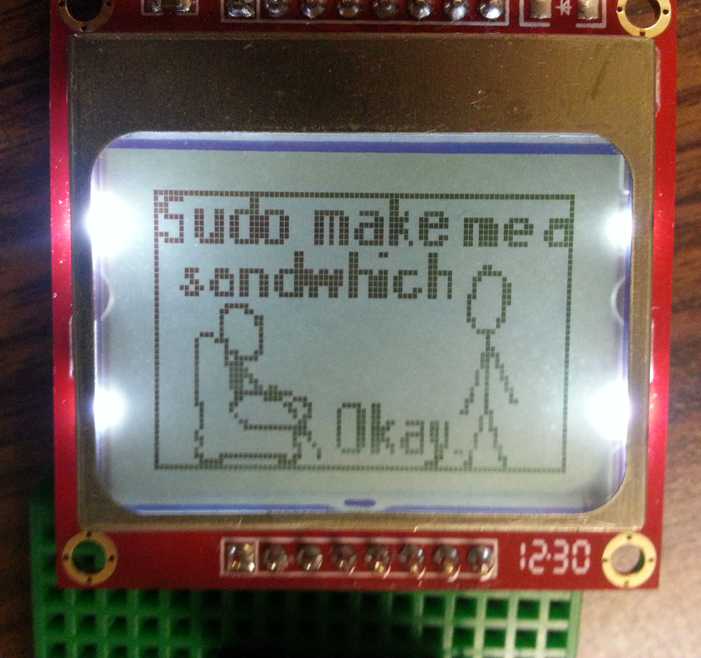
This is a demo of drawing bitmaps on the screen, which is one of the more rewarding tasks we can accomplish with the 'duino/LCD combo.
After the demo runs its course, the sketch will enter into a serial echo mode. Open the serial monitor (set the baud rate to 9600 bps), and type stuff over to the Arduino. It should start printing everything you send it onto the LCD.
If you're intrigued by the possibilities of drawing bitmaps on the screen, check out the next page! We'll show you how to import your own 84x48 bitmap and draw it on the screen.