GPS Differential Vector Pointer
Introduction
In this tutorial you'll learn how to use GPS receivers to have two objects, a base and a target, point towards one another. This can be used to aim sensors, antennas, lasers, etc. from one object to another over long distances.
Project Background
GPS technology is a very useful and elegant technology. The satellites used in the GPS network do most of the work so that the GPS receiver can be made small and simple. As GPS technology becomes more and more accurate, applications in many areas have really taken off. Some of these include driver-less cars, mission planning for UAVs, assisted landing of commercial aircraft and many more. GPS receivers vary in cost depending on accuracy and what other functions they provide, so the right receiver needs to be chosen for the desired application. In this project, I am demonstrating that an expensive receiver is not necessary to create an amazing project.
This project began as a proof of concept for the ANACONDA 2014/2015 Aerospace Senior project whose mission was to:
“Design and construct an autonomous tracking and communication support system for an antenna to be used to track unmanned aircraft during flight.”
If you want to check out this and other projects, follow the link below to the CU senior projects page, and go to the 2015 projects page.
Project Overview
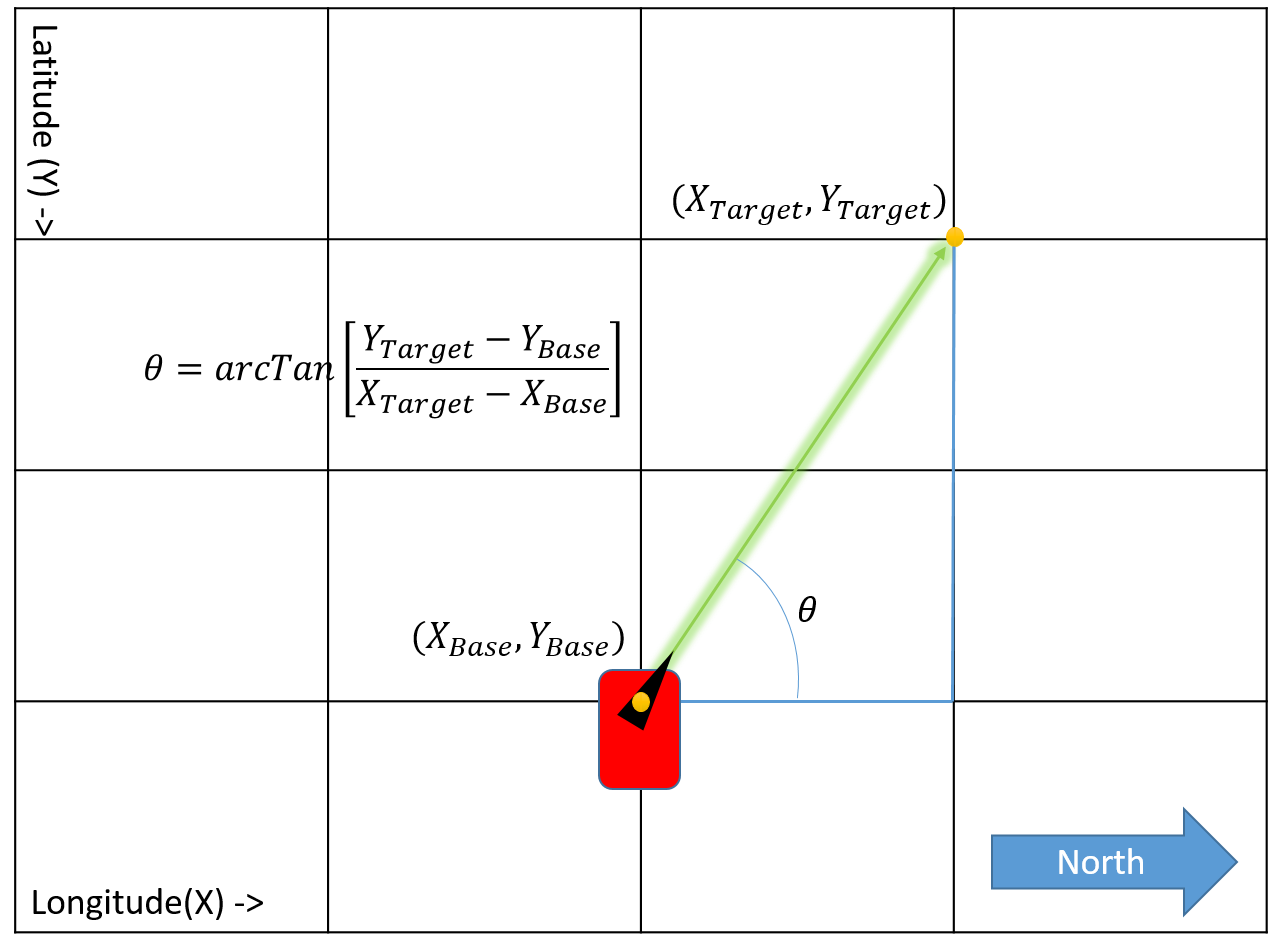
The underlying principle here is that, if two GPS locations are provided by two different receivers, a position vector can be calculated between them. This can be used to aim a directional antenna (or in the case of this project a laser) from one object (the base station) to the other object (the target) at any distance, which is only limited to your ability to provide the base station with the target's GPS location. The target's only purpose is to receives its GPS location, parse the data and send that back to the base station. The base station then receives the target's GPS location and compares it to its own GPS location to calculate the positional vector. The base station also includes a 180 degree servo and a laser, so the direction can be visualized.

Knowing the horizontal and the vertical difference between points, you can use the inverse tangent function to give you the pointing angle needed to control the mechanism. See the image below.
The final product looked like the following:
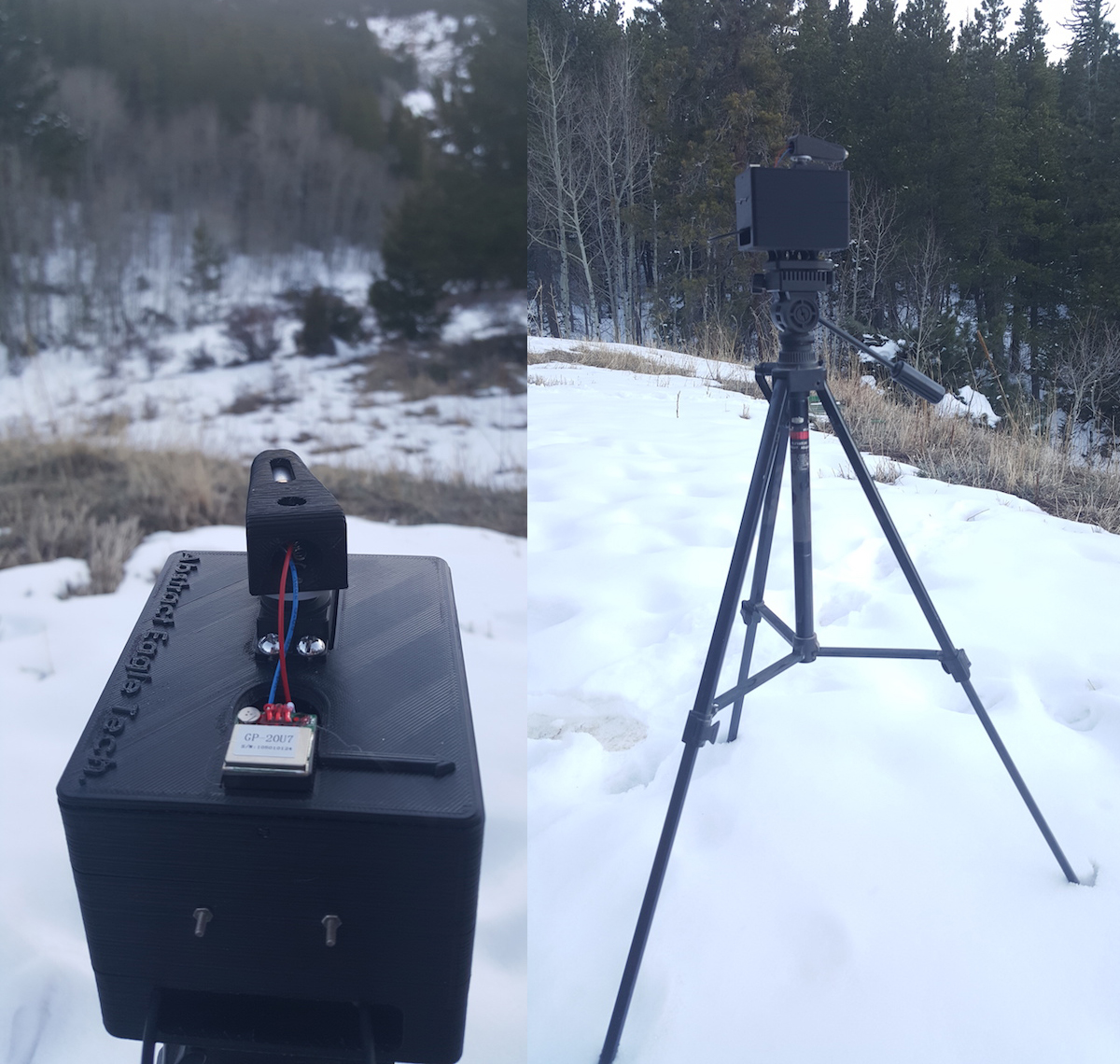
The image above shows the GPS antenna pointed down. Ideally, you would want to point the ceramic antenna facing the sky to receive the best satellite reception. In this tutorial, the satellites in view was sufficient enough for the project to function. Make sure to mount your GPS receiver with the antenna pointed toward the sky.
This tutorial will go over how to replicate this system.
Suggested Materials
To follow along with this tutorial, we recommend the following supplies:
Electrical Supplies
Here is a list of all the SparkFun materials you will need for this project:
Mechanical Supplies
You will need some hardware to mount electronics in the final system:
- Access to a 3D printer
- Tripod with universal camera mount platform
- Magnetic compass
- Mounting Hardware
- 4 X 8-32 Machine screws
- 3x 1/2” spacers with #5 sized through hole
- 3x 2-56 ½” Machine screws
- 3x 2-56 ¾” Machine screws
- 6x 2-56 Hex Nuts
- 6x 1-72 ½” Flathead screws
- 6x 1-72 Hex Nuts
- 2 x 0-80 Flathead screws
- 1 5/16th O-ring with 1/16th wall thickness or less
3D Models
A custom enclosure was created for each piece in this project. These files are provided in the link below, if you wish to download and print them. These files can also be found in the 3D Models section.
Suggested Reading
Before embarking upon this tutorial, you may find the following links useful: