GPS Differential Vector Pointer
System Assembly
This section will cover how to install the electronics in the 3D printed enclosures.
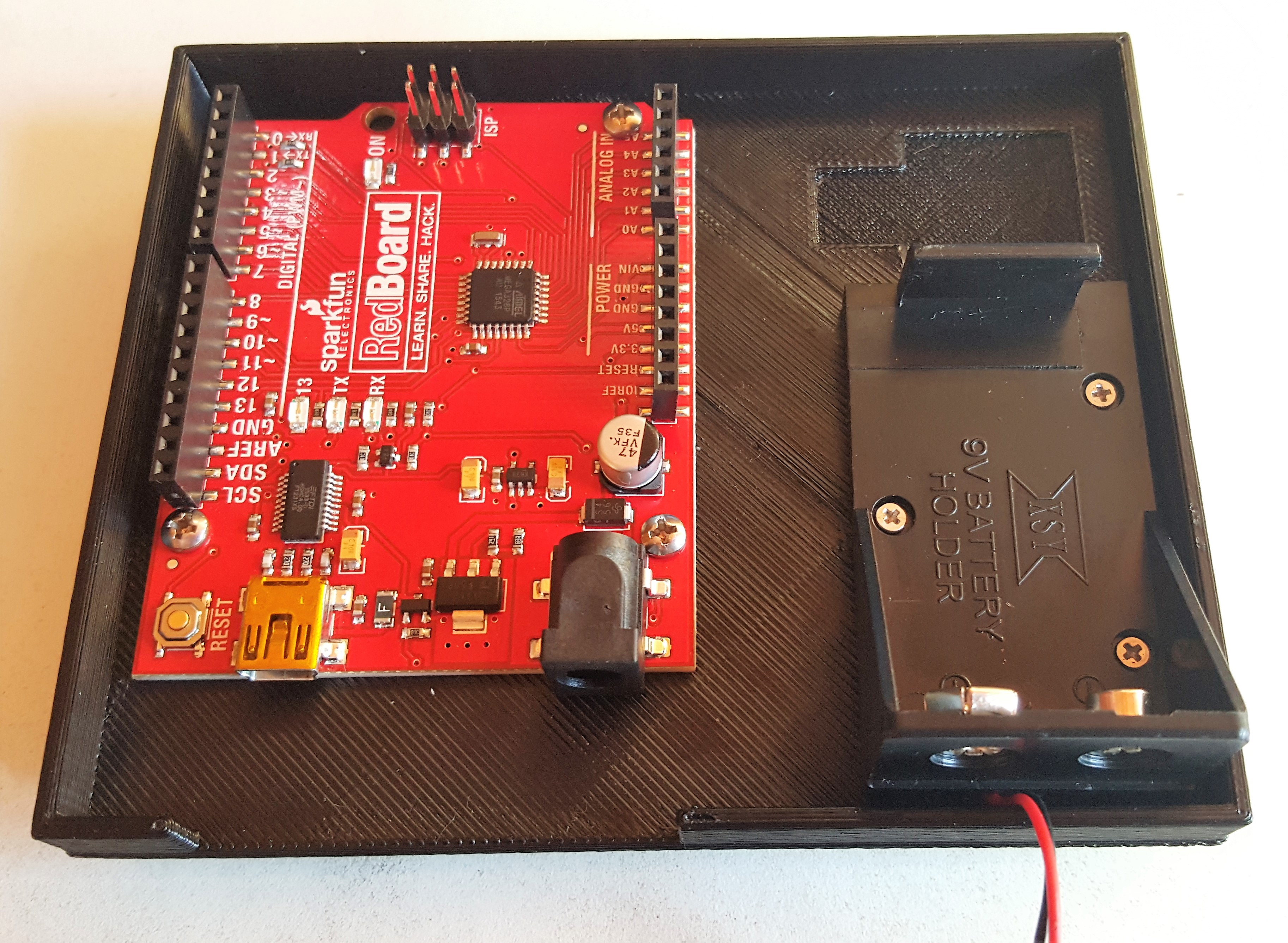
Base Station Bottom
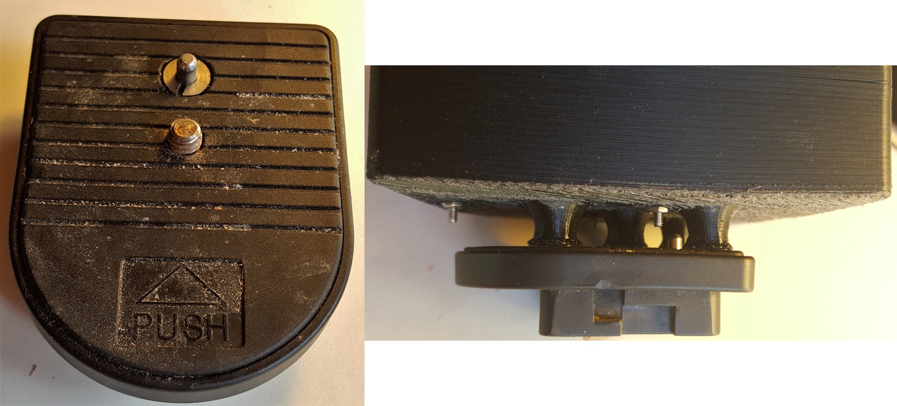
Attach the RedBoard to the base using 32-56 ¾” machine screws with the three spacers in between so it is elevated off the bottom of the case. This is to ensure that the mounting hole is available, which you may need depending on your tripod mounting situation.
Connect the 9V battery. Mount the battery enclosure onto the holes located on the wall of case.

Depending on your tripod, this step may be different. The tripod used in this guide had a piece with the mounting screw that can be threaded into the available mounting hole and works quite nicely.
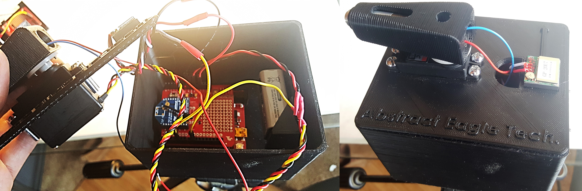
Base Station Top
Place the servo in the available cavity with the gear closer to the GPS cavity. Once in place, screw the four 8-32 screws into the available holes on the servo. You shouldn't need nuts for the other side since the holes are close fit and the ABS used is soft and allows them to easily thread themselves into place. If the servo moves around too much, you can add nuts for stability.
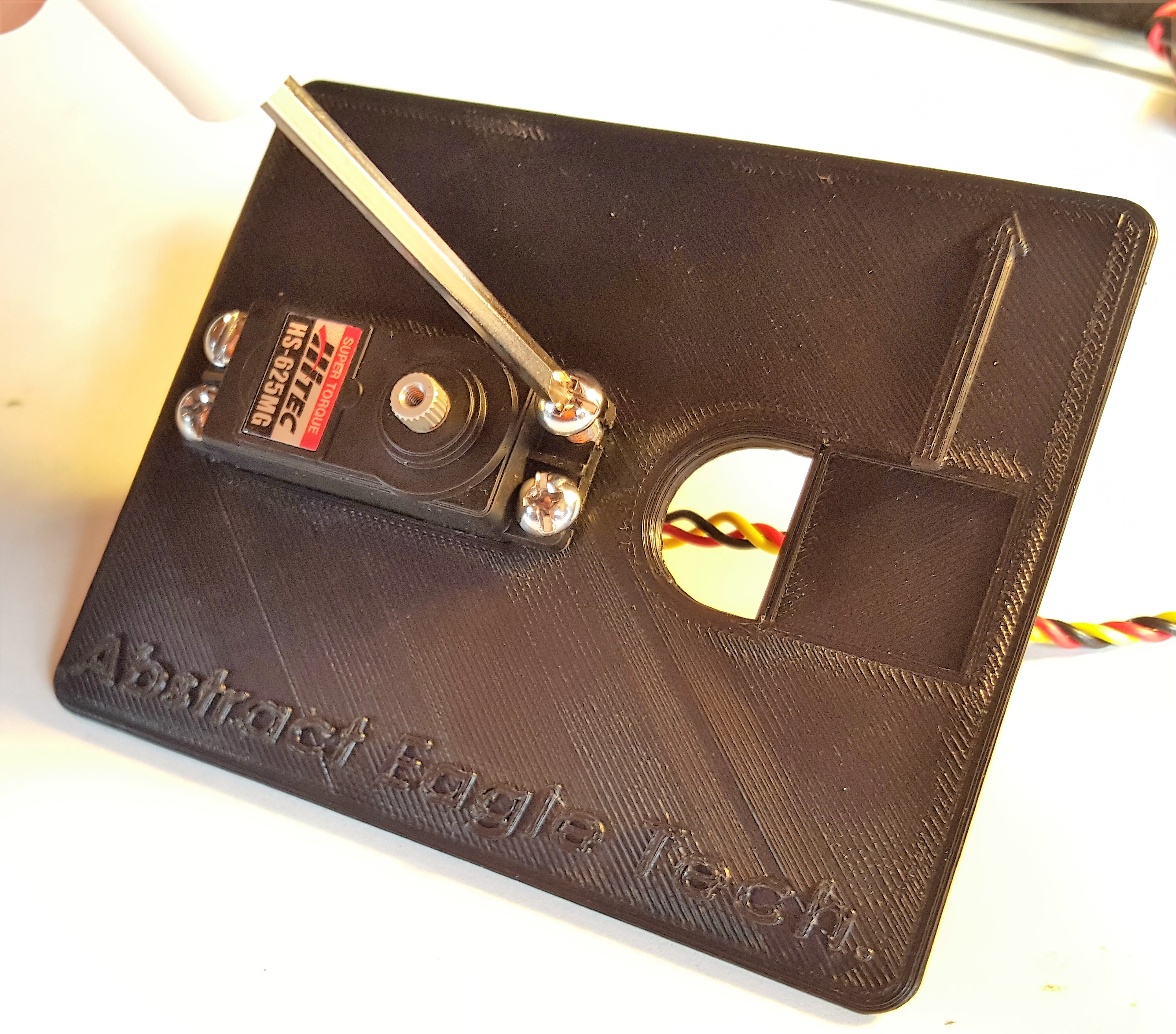
Attach the circular servo disk (a.k.a. horn) to the laser mount aligning the hole on the bottom of the laser mount with the hole on the disk. Attach this by placing two 0-80 Flathead screws through the countersunk holes within the laser cavity. You may need to open up the holes on the circular wheel since they will be used as pins, and you will not be able to screw them in. These are to ensure that the two parts are connected in the right orientation, and, if loose, you may need to use an adhesive to attach these.
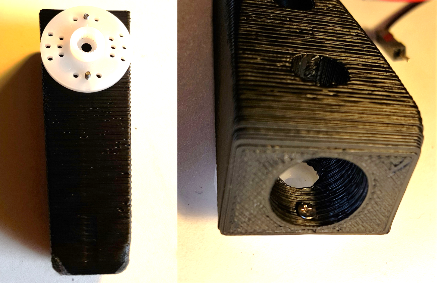
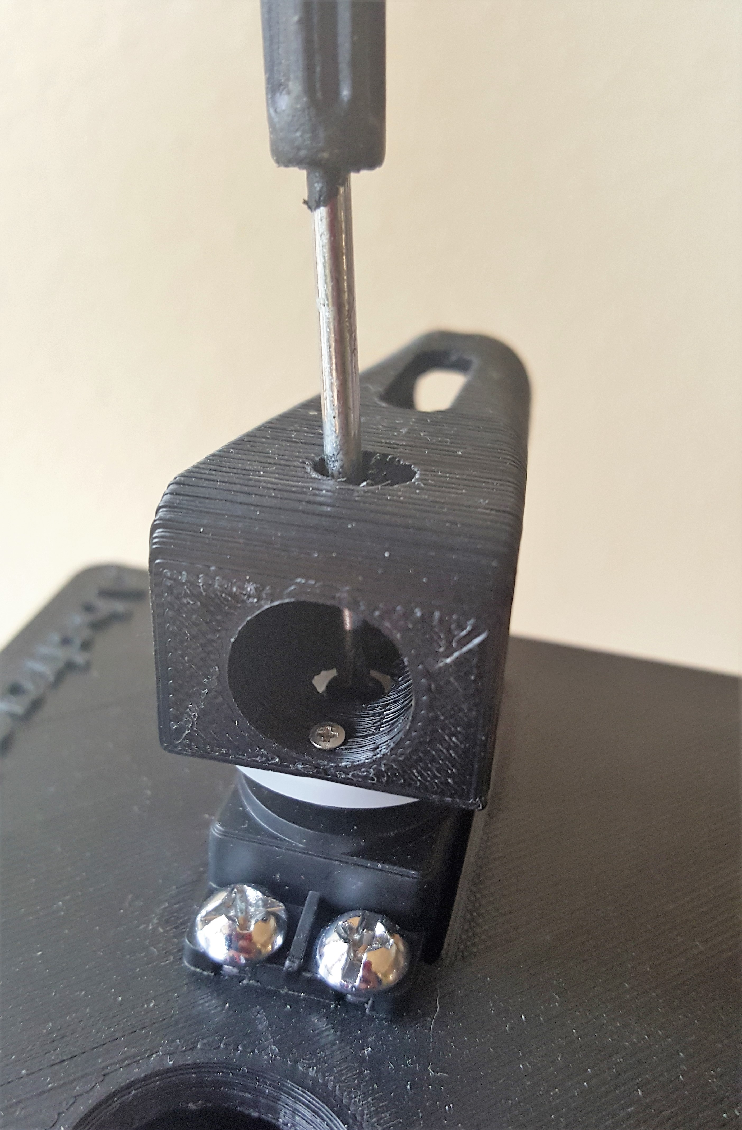
Next, attach this assembly to the servo. Slide the circular disk back onto the servo, then screw it to the servo, using to the available hole in the laser mount to access it with a screw driver.

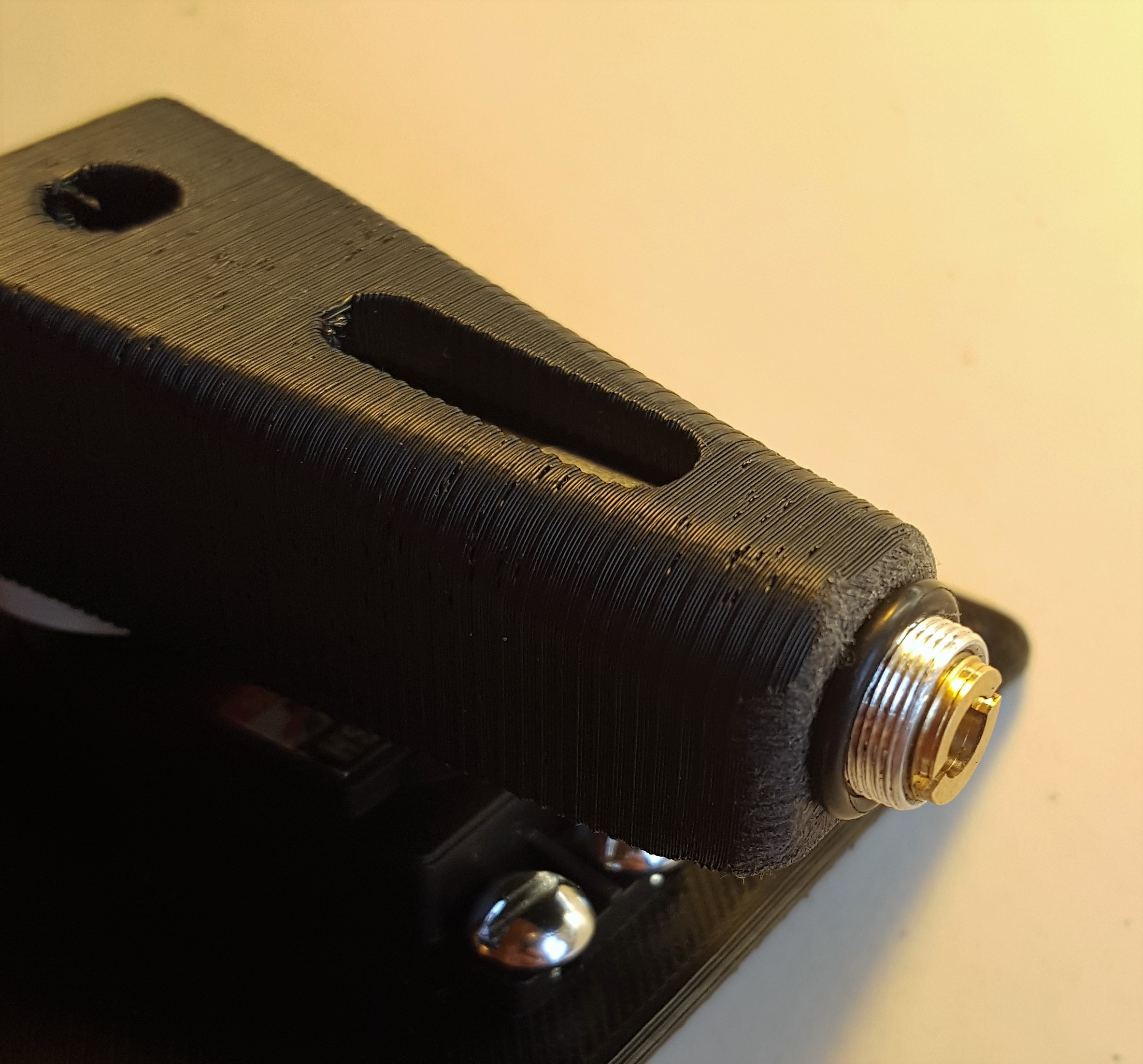
With the laser wired to the shield, push the laser through the hole in the top platform and into laser mount. Place the O-ring over exposed part of the laser to hold it in place. This can be a little finicky, so you can use hot glue to hold it in place.
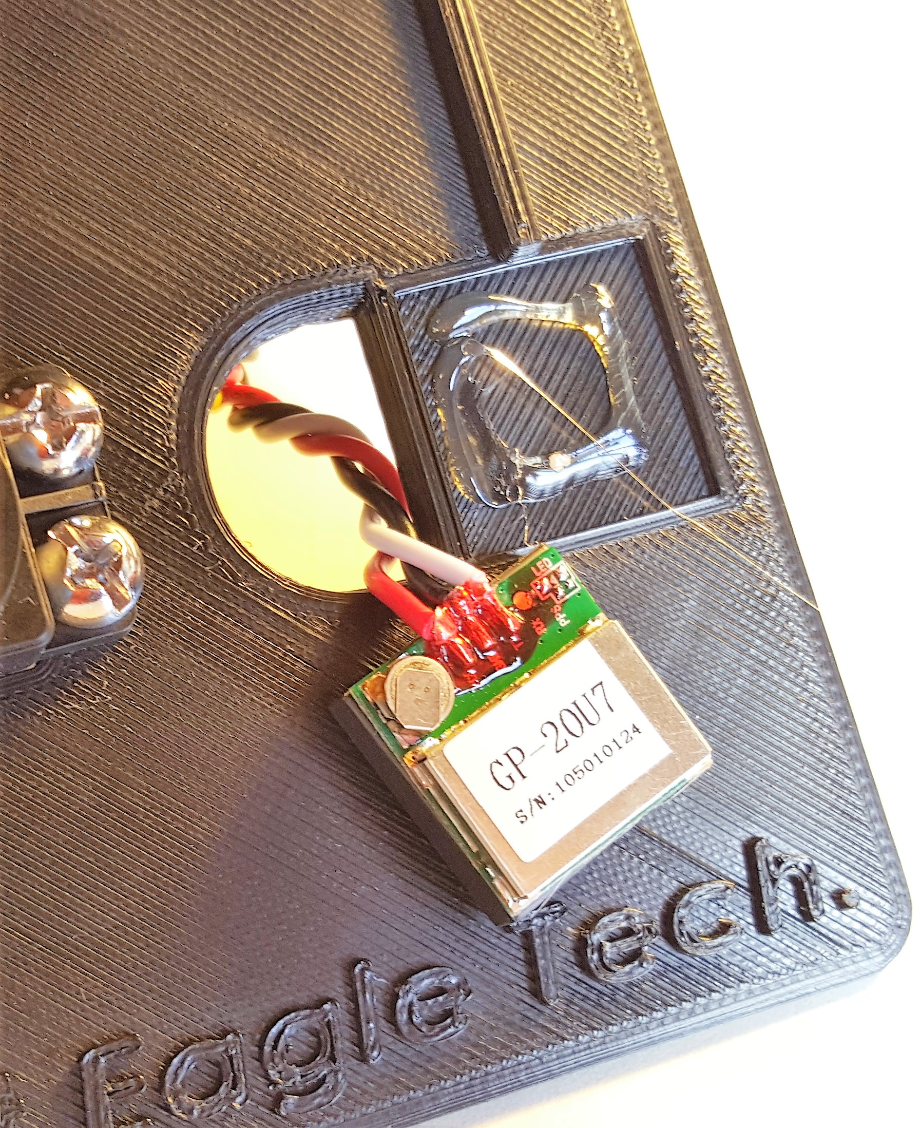
Attach the GPS receiver tot he indent made on top of the case. Again, make sure the wires stay inside the enclosure.
Attach the XBee Sheild to the RedBoard, if you haven't do so already, connect the wires, and you are good to go.
Target
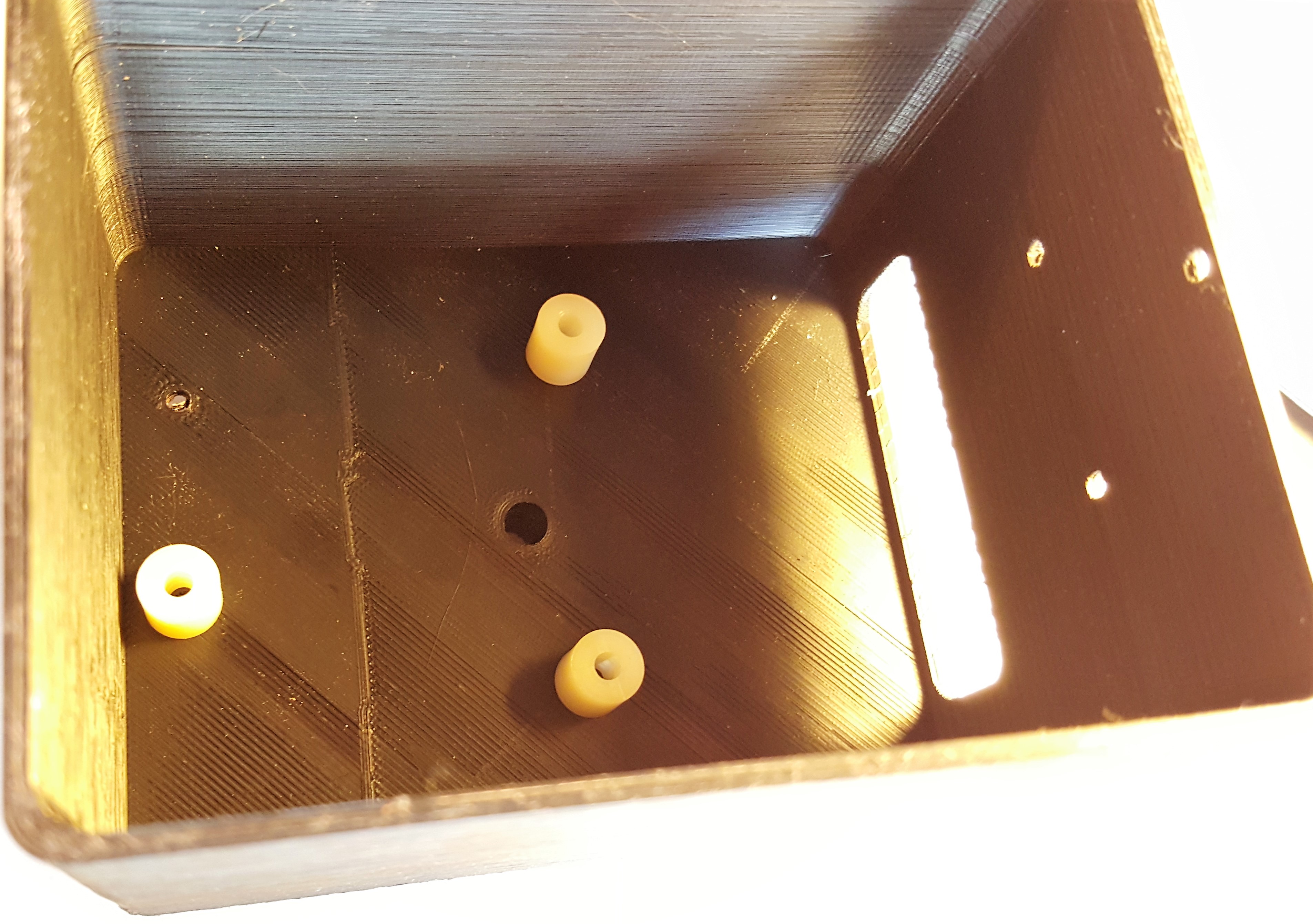
Place the bare RedBoard in target case so that the USB port is facing the opening, and place 3 2-56 ¾” Machine screws into any three available holes. Use the corresponding nuts to secure them in place from the back.
Attach the 9V Battery holder using 3 1-72 ½” flathead screws, and secure them using the corresponding nuts on the back.
There is a cavity made for the GPS receiver sunk into the base. Use a glue gun or other adhesive method to hold it in place. Once everything is attached, place the XBee Shield back on the RedBoard and connect everything as shown in the Electronics Assembly section.
