GPS Differential Vector Pointer
Electronics Assembly
All the electronics in this project plug directly into pins on the XBee Shield (with the exception of the laser diode), which makes this part pretty straightforward. I have designed this mechanism so that the connections are not permanent and can be taken apart, but you can solder the connections instead, if desired.
The first step is to configure both XBees so that they are set up on the right channel. This is described in detail in this tutorial.
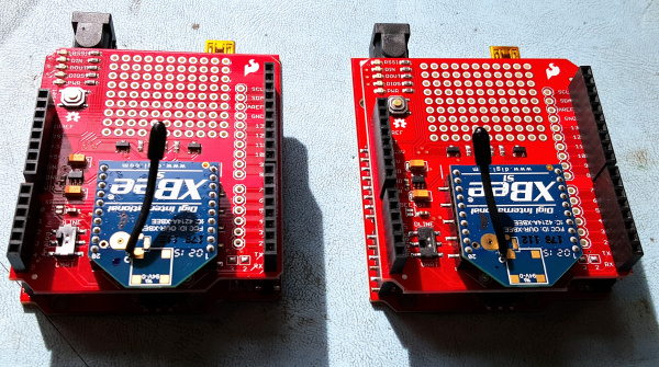
Once everything is configured, you will need to create two identical assemblies of the RedBoard with the XBee shields attached. Stackable headers will need to be soldered onto the XBee Shield, so that it can be mounted on top of the RedBoard and wires can still be attached. A detailed walk-through of this process is described here.
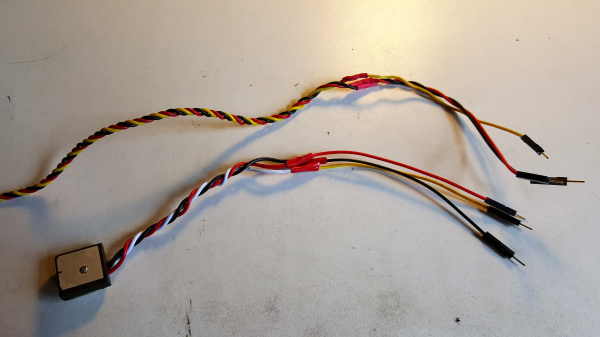
Next, prepare the wires of the two GPS receivers and the servo so they can easily be plugged into the shield. I cut off the existing connectors and soldered them to male jumper wires for easy pluggability. The wires for the target GPS receiver can be made shorter so you don't have excess wire. Make sure you leave enough length to reach the pins from where the receiver will be mounted.
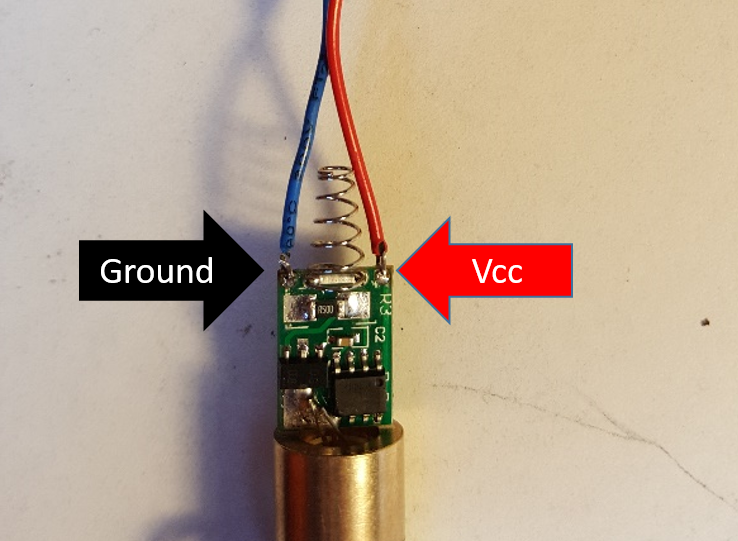
The last step will be to connect the Laser diode. To do this, you will first need to solder stranded wire to the two holes located on the laser PCB. Ensure they are attached to the correct pads, as shown here. Take care when soldering these pads as too much heat can damage the laser electronics.
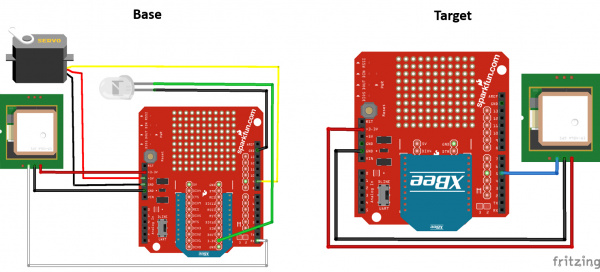
Because the laser will be moving, these wires should be soldered rather than just plugged in. This will be done on the XBee shield used on the Base. The following diagrams show how everything should be connected. Note that the LED in the diagram represents the laser.


