Getting Started with the SmartLED Shield for Teensy
 bboyho
Example: Matrix Clock w/ the DS1307 RTC Module
In this example, we will be using the DS1307 RTC module with the SmartLED Shield, Teensy 3.2, and 32x32 panel with 1:16 scan rate. We will use the included 2x8 header and IDC cable instead of mounting the shield on the back of the matrix.
Parts Needed
To follow this example, you would will need the following materials. You may not need everything though depending on what you have. Add it to your cart, read through the guide, and adjust the cart as necessary.Setting Up the DS1307 RTC Module
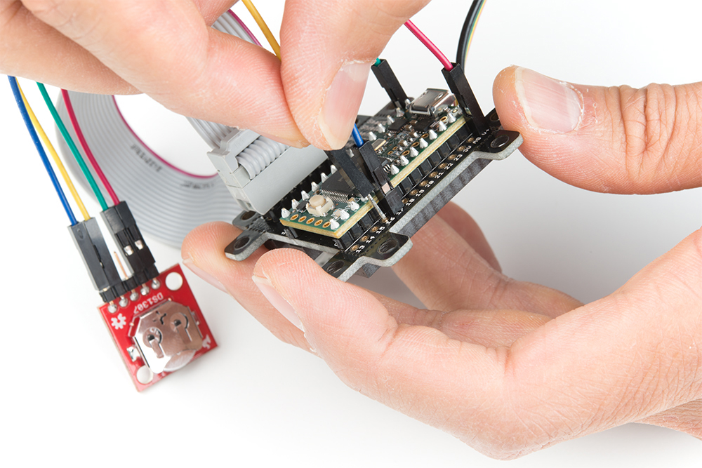
If you have not already, solder right angle headers to the RTC module.
Make sure that you installed PJRC's DS1307RTC and Time libraries with the Teensyduino add-on. You can check by viewing the Arduino program folder where the files were installed under. In this case, it was in the "...Arduino\hardware\teensy\avr\libraries" path.
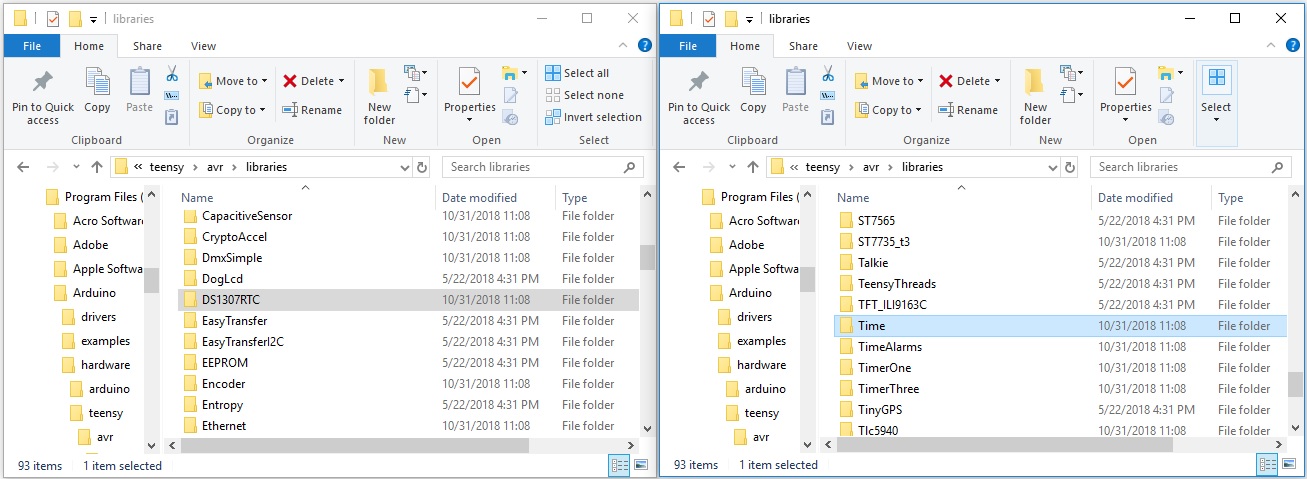
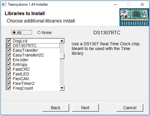
If it is not installed, you can run the Teensyduino add-on installer again to add the associated files. Under Libraries to Install, make sure that the checkbox is checked off for DS1307RTC and Time libraries.
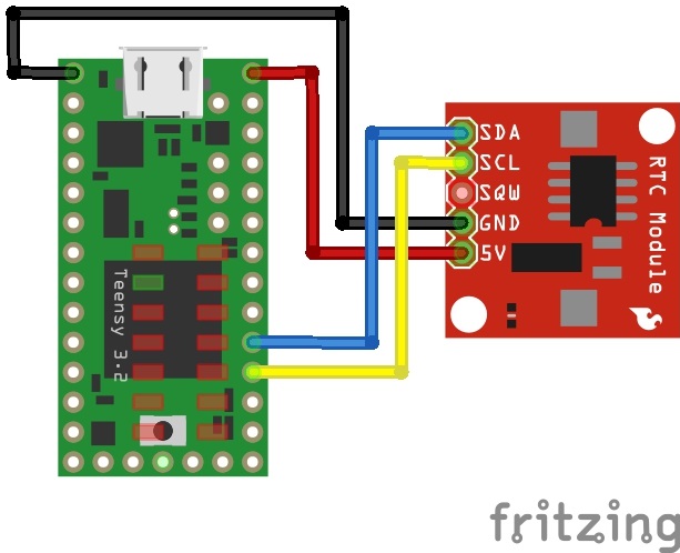
Circuit Diagram 1
Make the following connection between the DS1307 breakout board and Teensy stacked on the SmartLED shield. If you used right angle headers on the DS1307 breakout board, you can use four M/F jumper wires to connect.
Hookup Table 1
| DS1307 | Teensy |
|---|---|
| SDA | 18 |
| SCL | 19 |
| SQW | N/C |
| GND | GND |
| 5V | V+ |
Upload Code
In the Arduino IDE, open File > Examples > DS1307RTC > SetTime.ino. The sketch will automatically set the date and time for the RTC from the compiler once you upload. You will need to run this code if the battery was removed or the time does not match your time zone. Select the Teensy board definition with the associated COM port and click upload. To check if the clock matches your computer's time, simply open the Arduino serial monitor set at 9600 baud. You should see an output similar to the one shown below.
DS1307 configured Time=13:00:47, Date=Nov 12 2018
DS1307 Communication Error :-{
Please check your circuitry
MatrixClock
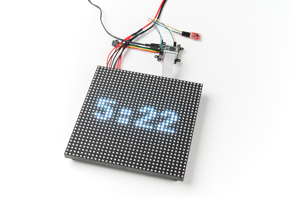
Now that the clock is configured, let's output the time to the 32x32 panel!
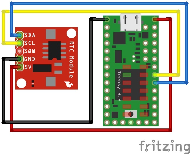
Circuit Diagram 2
Adjust the SDA and SCL wires as shown in the diagram below.
Hookup Table 2
| DS1307 | Teensy |
|---|---|
| SDA | 17 |
| SCL | 16 |
| SQW | N/C |
| GND | GND |
| 5V | V+ |
Notice that the wires are in a different location and flipped? Well that's because the I2C pins are redefined for the SmartMatrix Shield! Make sure to move the pins and switch the order that they are connected.
Modifying Code
Next, open the MatrixClock.ino example by clicking on File > Examples > SmartMatrix > MatrixClock in the Arduino IDE. Since we are using the SmartLED shield and the 32x32 panel with 1:16 scan rate, there is only one line of code that needs to be adjusted. We just need to:
- uncommenting the line for your hardware configuration
- in this case, we chose "
#include <MatrixHardware_Teensy3_ShieldV4.h>" for the Teensy 3 by removing the "//"
- in this case, we chose "
Upload Code
Once the code has been adjusted, select correct board and COM port to upload to the Teensy 3.2. Connect the IDC cable to the SmartLED shield with the 2x8 male header pins. Then add power to the panel and Teensy to view begin viewing the time!