Getting Started with the SmartLED Shield for Teensy
 bboyho
Hardware Assembly
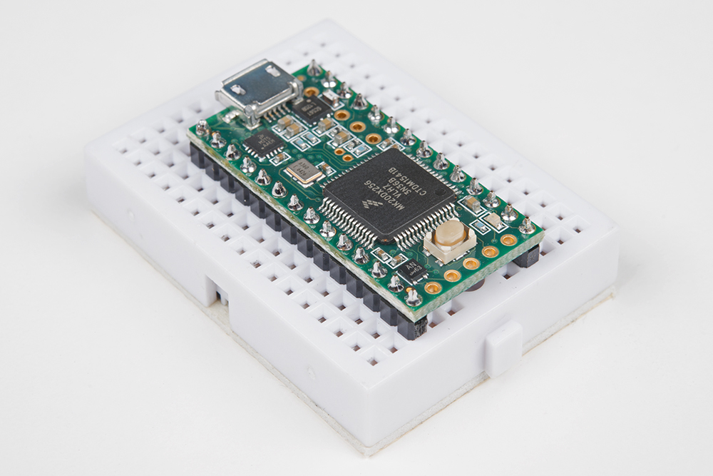
If you have not already, solder the male header pins on your Teensy before connecting. We will be using the 1x14 header pins on each side of a Teensy but you can also solder additional pins or or wires depending on your setup.
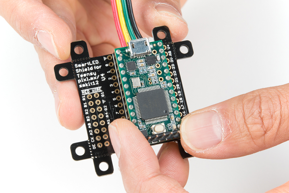
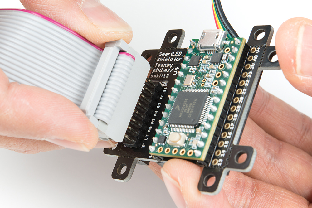
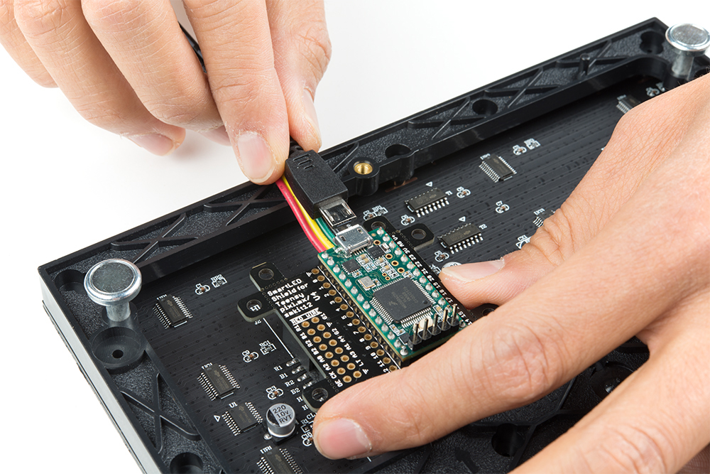
After soldering and removing the flux from a Teensy, stack the Teensy on the SmartLED shield. Make sure to face the USB connector in the same direction as the 4-pin JST SM connector.
Align the IDC connector breakout on the SmartLED shield with the IDC connector on your RGB LED Matrix Panel. The location of the IDC connector depends on the manufacturer of the panel but usually it will be located on the left side relative to the arrows pointing up and toward the right.
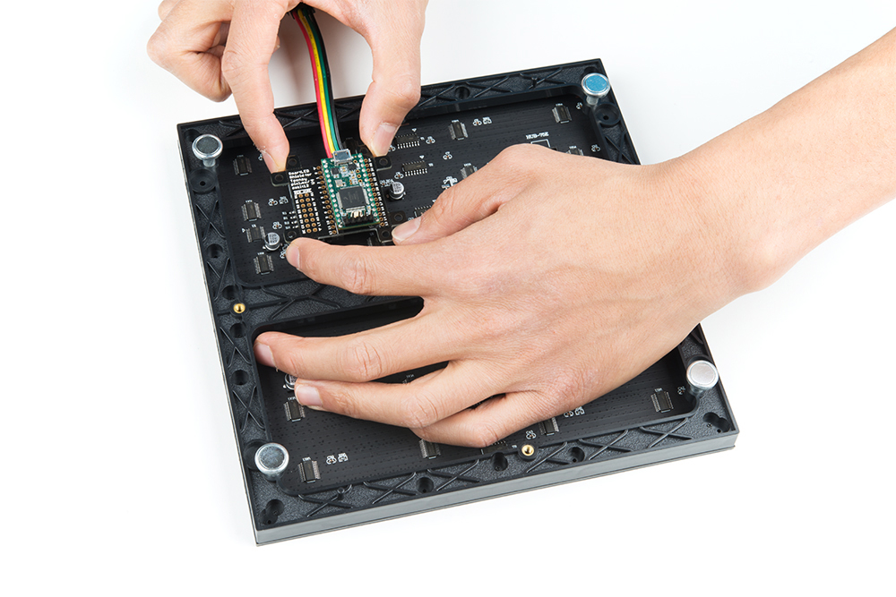
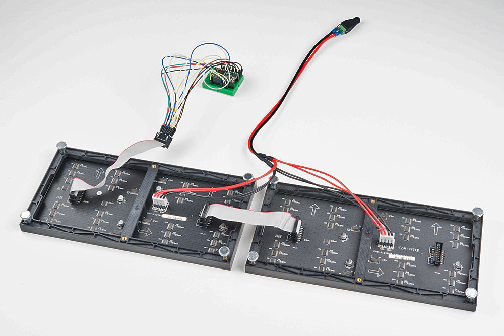
Once connected, the back of your RGB LED matrix panel should look similar to the images below. On the left, a Teensy 3.2 was connected to a 64x64 panel with 3mm pitched LEDs. On the right, a Teensy 3.6 was used for a 32x32 with 6mm pitched LEDs.
 |
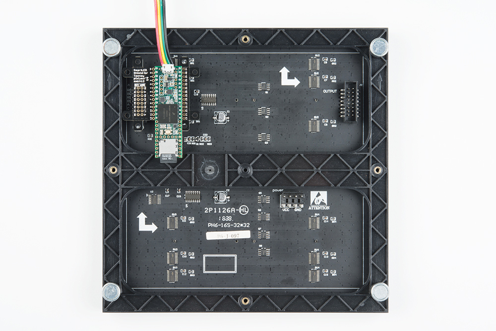 |
If you have not already, attach a 5V power supply to your RGB LED matrix panel's power cable. If you are using a power supply with a barrel jack, you can use a female barrel jack adapter and screwdriver to get a quick and dirty connection between the spade and barrel jack.
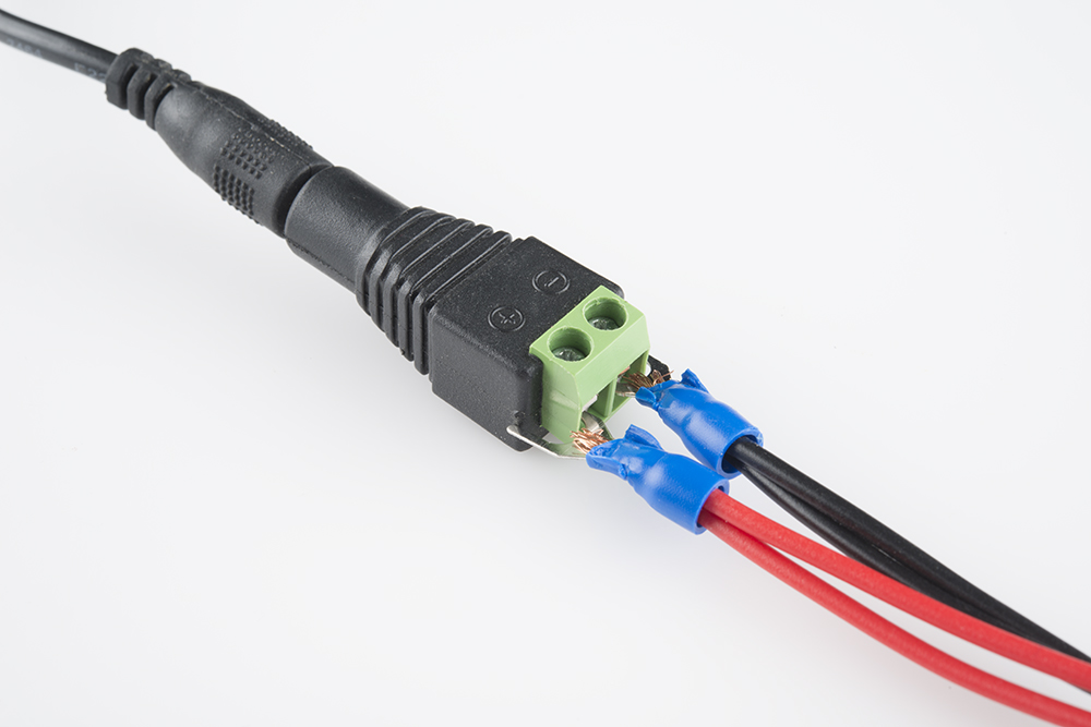
The connection should look similar to the image below. Depending on your 5V power supply, your setup might be slightly different.

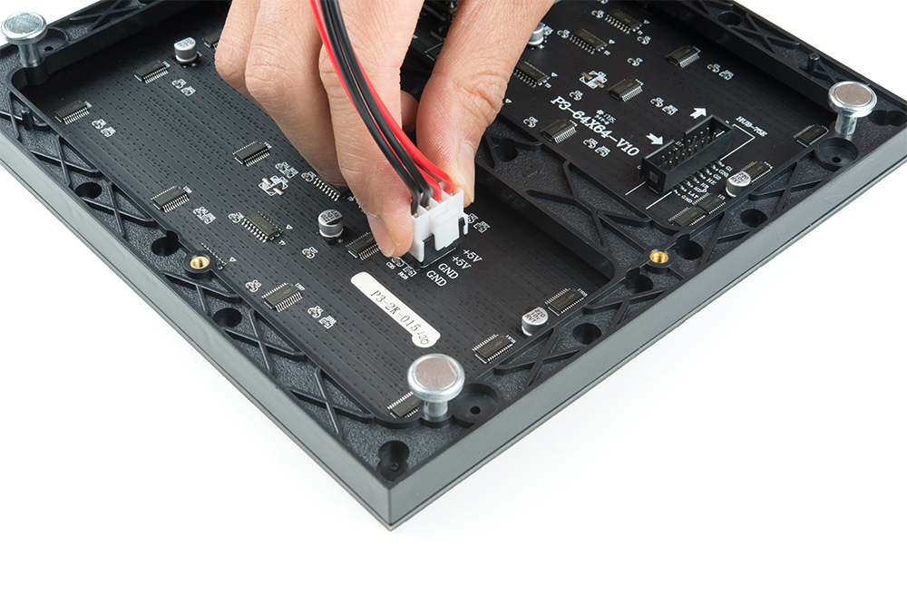
Then slide the polarized power cable for the RGB matrix panel into its respective mating connector. The red wires should be connected to the 5V pins while the black wires connected to the GND pins.
For the scope of this tutorial, we will connect 5V USB power directly to the Teensy's USB connector. This is separate from the power supply that is powering the RGB LED matrix panel. Depending on your setup, you can use the same power supply that the RGB LED matrix panel is using by connecting to either the Teensy's V+ and GND pins or the APA102 JST SM connector. Just make sure that the voltage is regulated at 5V.
Alternative Connections
There is an option to daisy chain the panels together if you are within the limits of the SmartLED library. Simply connect the output from the first panel to the input of the second panel. Make sure to provide power to each panel through the 4-pin polarized connector.
As explained earlier, you can try to wire all 16 pins from the Teensy to the panel's IDC cable. It is not the most reliable connection. There is a higher probability of wiring incorrectly or a connection becoming loose. For more information on trying the connection, check out the table below. This connection is not possible when wiring to a 64x64 panel due to the extra 5th addressing pin.
| Panel Pin Label | Cable Connector Pin # | Teensy 3 | Notes |
|---|---|---|---|
| R0 | 1 | 2 | Red Data (columns 1-16) |
| G0 | 2 | 5 | Green Data (columns 1-16) |
| B0 | 3 | 6 | Blue Data (columns 1-16) |
| GND | 4 | GND | Ground |
| R1 | 5 | 21 | Red Data (columns 17-32) |
| G1 | 6 | 8 | Green Data (columns 17-32) |
| B1 | 7 | 20 | Blue Data (columns 17-32) |
| GND | 8 | GND | Ground |
| A | 9 | 15 | Demux Input A0 |
| B | 10 | 22 | Demux Input A1 |
| C | 11 | 23 | Demux Input A2 |
| D | 12 | 9 | Demux Input E1, E3 (32x32 panels only) |
| CLK | 13 | 14 | LED Drivers' Clock |
| STB | 14 | 3, 8 | LED Drivers' Latch |
| OE | 15 | 4 | LED Drivers' Output Enable |
| GND | 16 | GND | Ground |