Getting Started with the A111 Pulsed Radar Sensor
 jimblom,
  bboyho,
  Elias The Sparkiest
Hardware Overview
- PTH for VCCIO
- Bypass jumper to set VCCIO to VIN
- Silkscreen name change for input voltage (5V => VIN)
- Improved logic level translation on the Raspberry Pi side
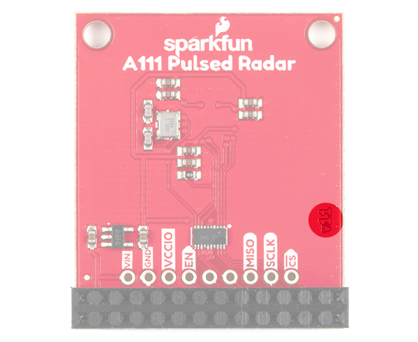
This section covers the hardware overview of both versions of the board. To see what version of the board that you have, you can check the back of the board near the CS pin. You'll also notice the additional bypass jumper on v1.1 that was not included on v1.0.
 |
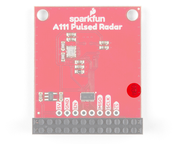 |
| Version number on the back of the board for v1.1 and v1.0 | |
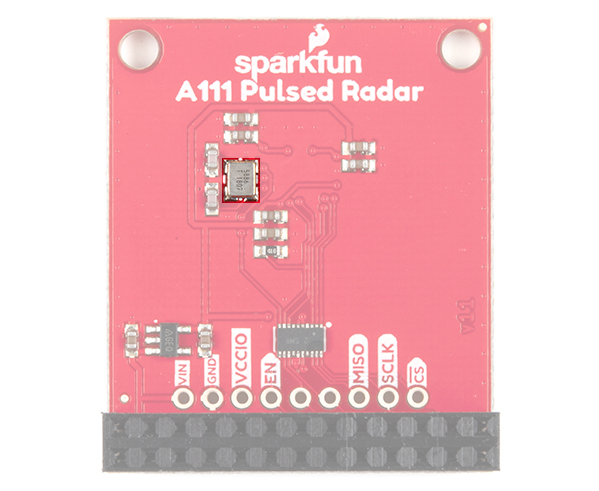
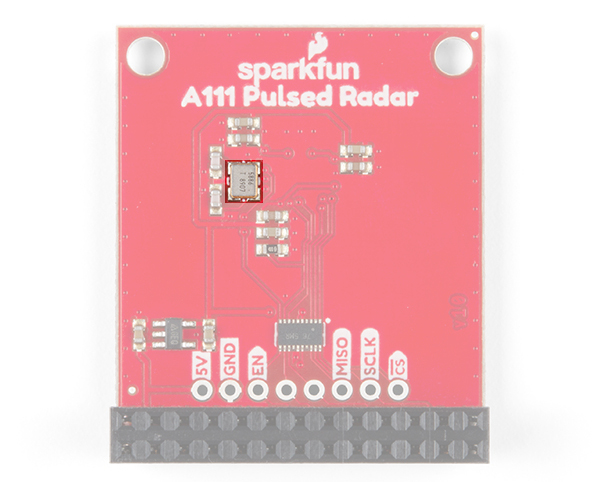
Sensor and Crystal
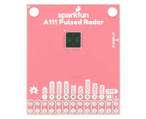
The breakout board is populated with the A111 IC and an external 26MHz crystal oscillator. The IC comes with two antennae and uses mmWave radio to sense objects via radar pulses.
 |
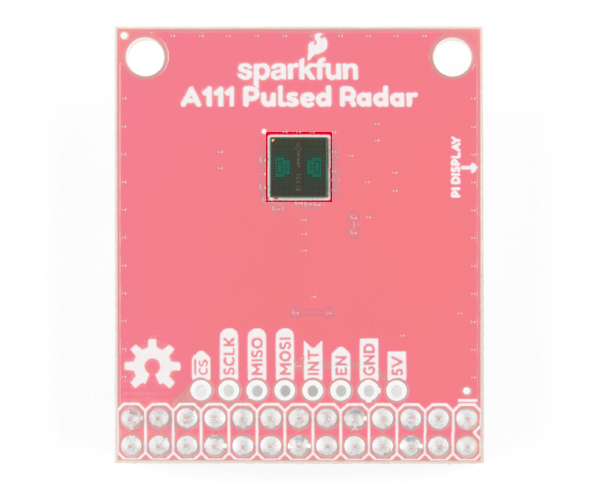 |
| A111 Populated on Top v1.1 and v1.0 | |
You'll find the external crystal oscillator populated on the back of the board. The location is the same on both versions of the board.
 |
 |
| Crystal Oscillator Populated on Back v1.1 and v1.0 | |
2x13 Female Header
To keep the size of the board small, there is a 2x13 female header soldered on the board to easily mate with a Raspberry Pi's standard header.
 |
 |
| HAT Standard Header with Female Connector v1.1 and v1.0 | |
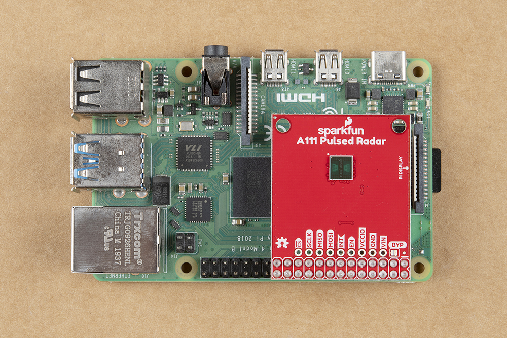
This should only cover the part of the 2x20 male headers on the Pi. Regardless of the version number, the HAT will be stacked near the display port's ribbon cable connector.
 |
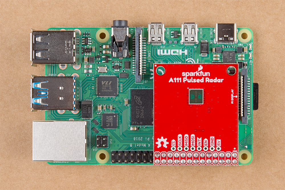 |
| A111 HAT v1.1 and v1.0 Stacked on a Raspberry Pi | |
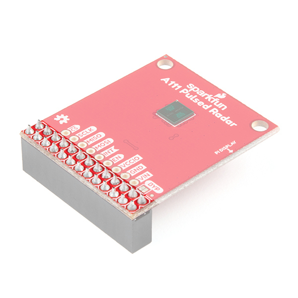
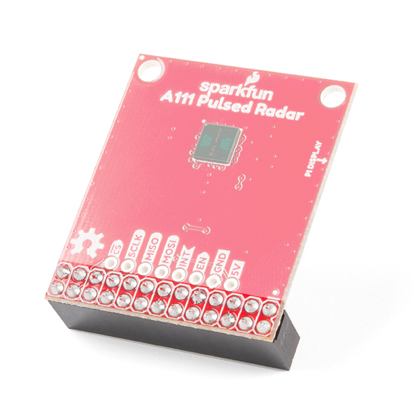
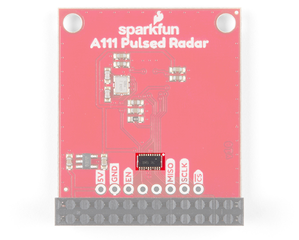
Additional Pins and Jumper Broken Out
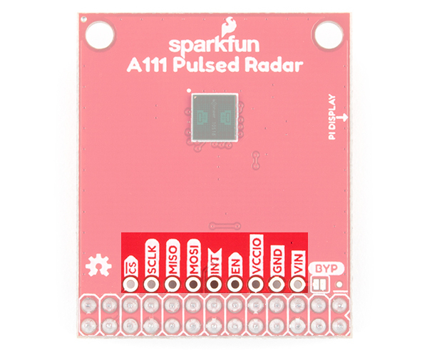
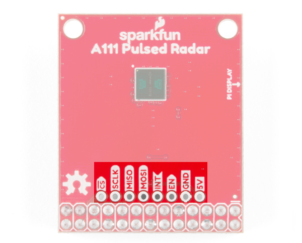
Just above the 26-Pin header, there are additional pins broken out for SPI, interrupt, enable, and power if you need access to the pins. Note that in v1.1, the input voltage is labeled as VIN while 1.0 labels the pin as 5V. Both pins are connected to 5V of the Raspberry Pi's HAT standard pinout. For v1.1, the additional PTH for VCCIO is included between the enable and GND pin. For v1.1, additional pins are shifted and align with the 2x13 header.
 |
 |
| Pins broken out on v1.1 and v1.0 | |
For v1.1, you'll also notice a bypass jumper (labeled as BYP). Adding a solder jumper to the board will set VCCIO to VIN.
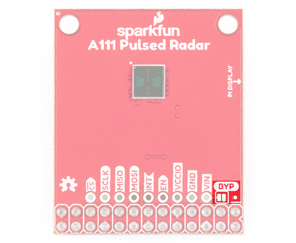
BYP pin will set VCCIO to VIN. If you are stacking the HAT on a Raspberry Pi, this will set the logic level on the Raspberry Pi's side to 5V.We recommend leaving this jumper alone when stacking the board on a Pi.
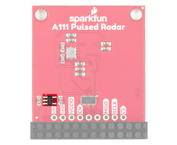
The A111 IC requires an input voltage of 1.8V, so a voltage regulator is populated on the back.
 |
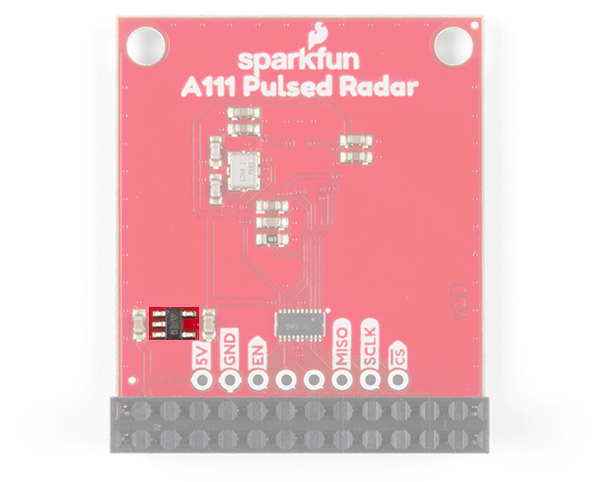 |
| Voltage Regulator on v1.1 and v1.0 | |
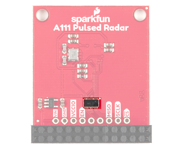
Additionally, the I/O logic level on the A111 is 1.8V, so a logic converter is included to translate the signals between the Raspberry Pi.
 |
 |
| Logic Level Converter on v1.1 and v1.0 | |
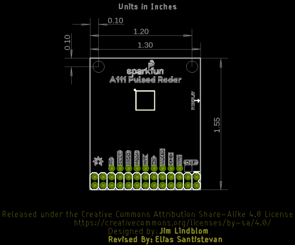
Board Dimensions
The overall board size is 1.30in x 1.55in. There are two additional mounting holes spaced 0.10 inches away from the edge of the board.
 |
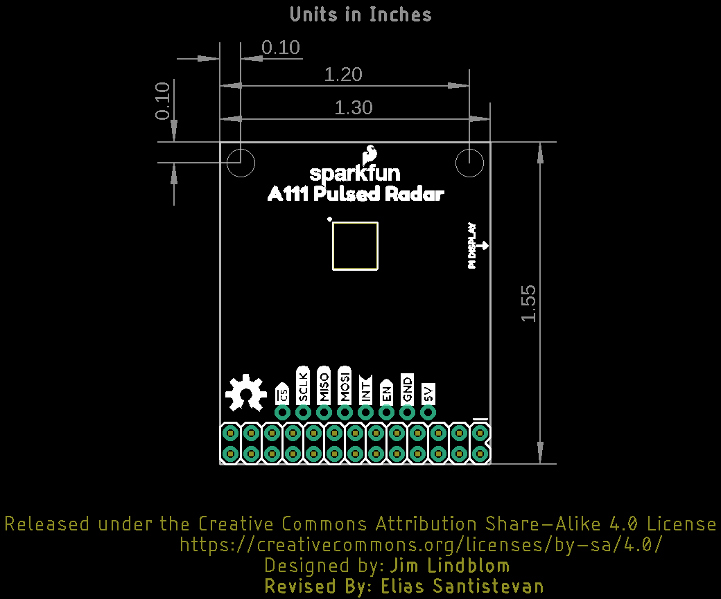 |
| Board Dimensions for v1.1 and v1.0 | |