Getting Started with the A111 Pulsed Radar Sensor
 jimblom,
  bboyho,
  Elias The Sparkiest
Hardware Assembly
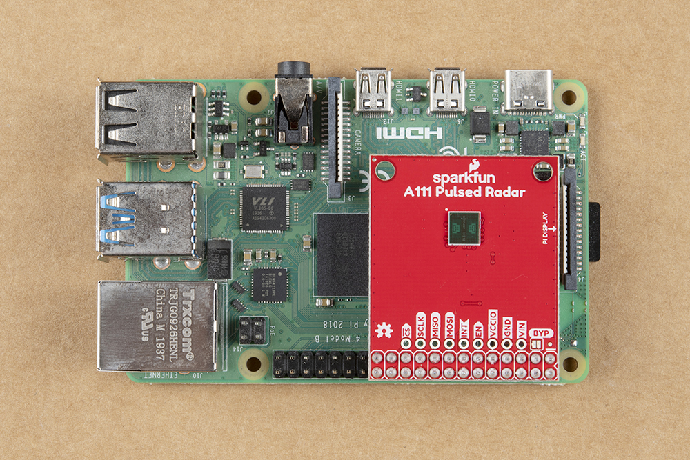
The A111 Pulsed Radar Breakout is designed to sit directly on top of a Raspberry Pi. Again, it doesn't span all 40 (2x20) pins of a Raspberry Pi B+ (or later), but the 26-pin — 2x13 — header should be compatible with any Pi.
Connect the shield to a Raspberry Pi ensuring that the "Pi Display" text on the breakout matches up with the display header on your Pi. The sensor should be facing up after plugging it in.
 |
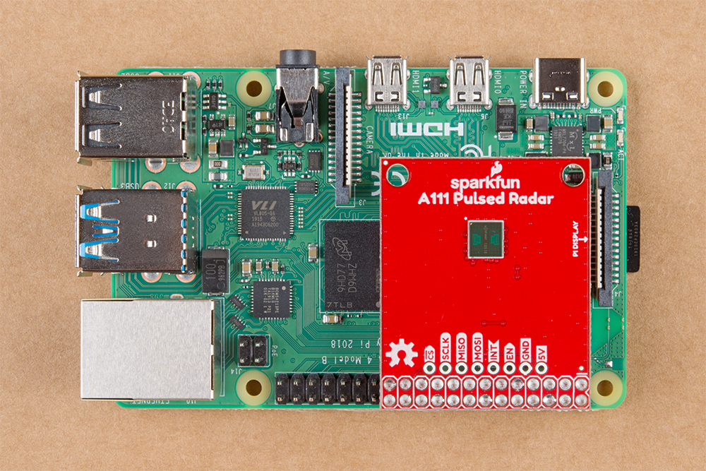 |
| A111 HAT v1.1 and v1.0 Stacked on a Raspberry Pi | |
Or, if you'd like to manually wire the breakout up to a Raspberry Pi's standard pinout, here is the pin-out we'll use through the rest of this tutorial. As stated in the hardware overview for v1.1, the input voltage is labeled as VIN while 1.0 labels the pin as 5V. Both pins are connected to 5V of the Raspberry Pi's HAT standard pinout. For v1.1, the additional PTH for VCCIO is included between the enable and GND pin.
| v1.1 Breakout Pin | v1.0 Breakout Pin | Raspberry Pi Pin Name | RasPi Hardware Pin Number |
|---|---|---|---|
| CS | CS | SPI0 CS0 | 24 |
| SCLK | SCLK | SPI0 SCLK | 23 |
| MISO | MISO | SPI0 MISO | 21 |
| MOSI | MOSI | SPI0 MOSI | 19 |
| INT | INT | GPIO25 | 22 |
| EN | EN | GPIO27 | 13 |
| VCCIO | 3.3V | 1, 17 | |
| GND | GND | GND | 6, 14, 20, etc. |
| VIN | 5V | 5V | 2, 4 |
When connecting to the additional pins broken out next to the Raspberry Pi's I/O, make sure to not accidentally connect anything higher than 3.3V since it is only 3.3V tolerant.