Getting Started with the A111 Pulsed Radar Sensor
 jimblom,
  bboyho,
  Elias The Sparkiest
 Introduction
Does your project require high-precision, cutting-edge distance, speed, motion, and/or gesture sensing? We're not talking ultrasonic, or even infrared here, but 60GHz radar! Say hello to our tiny, pulsed radar friend the Acconeer A111!
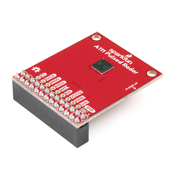
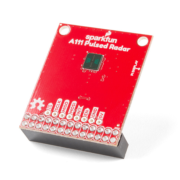
SparkFun Pulsed Radar Breakout - A111
SEN-15577The A111 is a single-chip solution for pulsed coherent radar (PCR) -- it comes complete with antennae and an SPI interface capable of speeds of up to 50MHz. Applications for PCR include distance-sensing, gesture, motion, and speed detection. The sensor can monitor one-or-more objects at distances of up to two meters.
Our breakout board for the A111 includes a 1.8V regulator, voltage-level translation, and it breaks out all pins of the pulsed radar sensor to both 0.1-inch and Raspberry Pi-friendly headers.
Required Materials
To use the A111 you'll need either an ARMv7 or an ARM Cortex-M4 -- the closed-source SDK currently only supports these architectures. This tutorial will explain how to use the radar sensor with a Raspberry Pi -- a platform based on an architecture supported by the A111's SDK.
The A111 Breakout includes a 20-pin, 2x10 female header, which should mate to Raspberry Pi's of any generation. If you'd rather manually wire the A111 to your Raspberry Pi and about 9x male-to-female wires should do the trick.


Raspberry Pi 3 B+ Starter Kit
KIT-15361Optional Materials
You have several options when it comes to working with the Raspberry Pi. Most commonly, the Pi is used as a standalone computer, which requires a monitor, keyboard, and mouse (listed below). To save on costs, the Pi can also be used as a headless computer (without a monitor, keyboard, and mouse). This setup has a slightly more difficult learning curve, as you will need to use the command-line interface (CLI) from another computer. However, you can also connect to a headless Pi using a remote desktop connection with VNC as well from another computer after configuring the settings.

Suggested Reading
If you have not set up a Raspberry Pi before, we recommend looking at the following tutorials to get started. Overall, the setup is the same regardless of the version that you have.
Raspberry Pi 4 Kit Hookup Guide
Raspberry Pi 3 Starter Kit Hookup Guide
If you aren’t familiar with the following concepts, we recommend checking out these tutorials before continuing. Using the Pi as a headless setup or with VNC can be useful when developing applications with the Pi.
Raspberry Pi SPI and I2C Tutorial
Headless Raspberry Pi Setup
How to Use Remote Desktop on the Raspberry Pi with VNC
Hardware Overview
- PTH for VCCIO
- Bypass jumper to set VCCIO to VIN
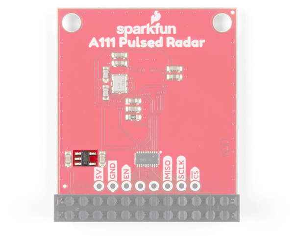
- Silkscreen name change for input voltage (5V => VIN)
- Improved logic level translation on the Raspberry Pi side
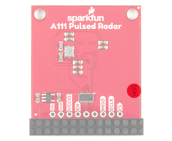
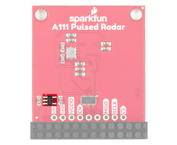
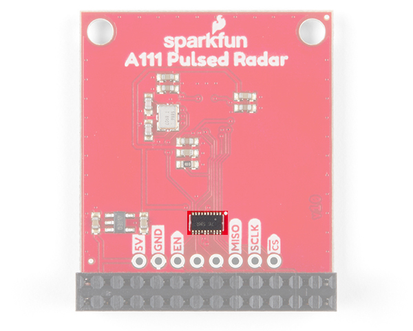
This section covers the hardware overview of both versions of the board. To see what version of the board that you have, you can check the back of the board near the CS pin. You'll also notice the additional bypass jumper on v1.1 that was not included on v1.0.
 |
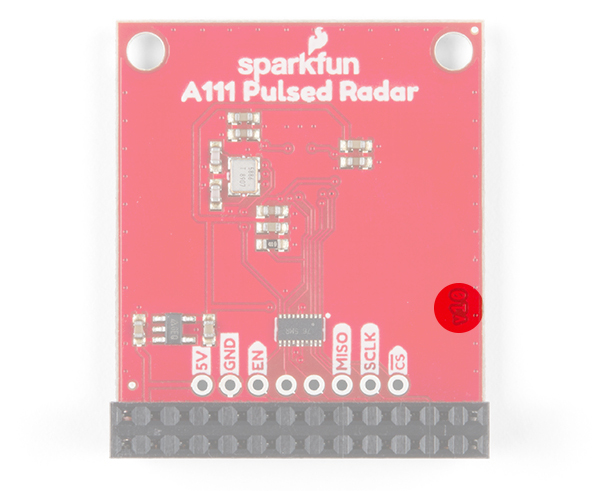 |
| Version number on the back of the board for v1.1 and v1.0 | |
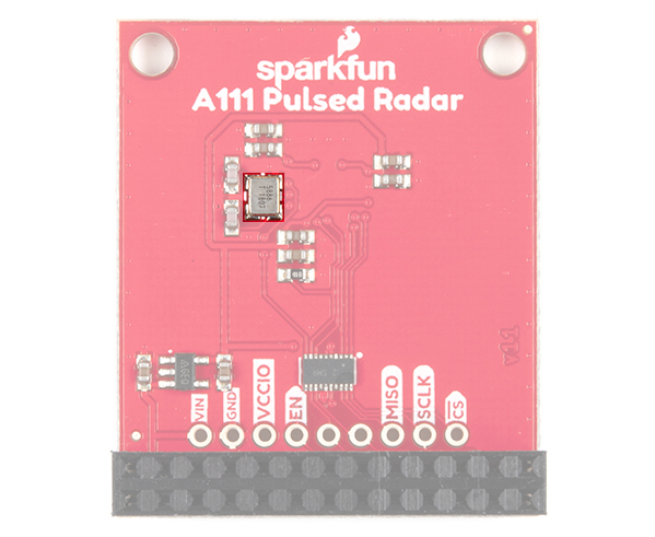
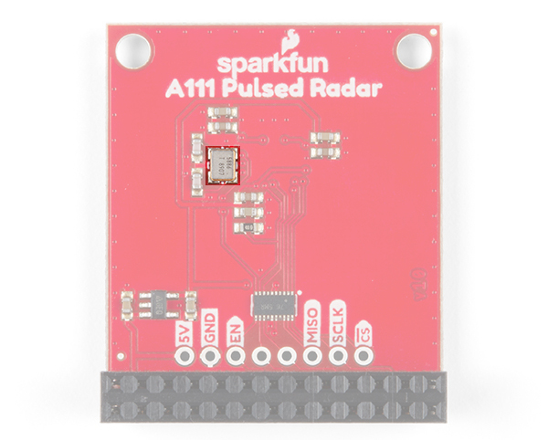
Sensor and Crystal
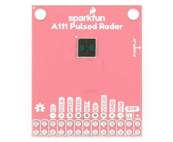
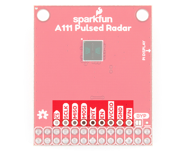
The breakout board is populated with the A111 IC and an external 26MHz crystal oscillator. The IC comes with two antennae and uses mmWave radio to sense objects via radar pulses.
 |
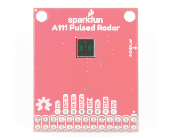 |
| A111 Populated on Top v1.1 and v1.0 | |
You'll find the external crystal oscillator populated on the back of the board. The location is the same on both versions of the board.
 |
 |
| Crystal Oscillator Populated on Back v1.1 and v1.0 | |
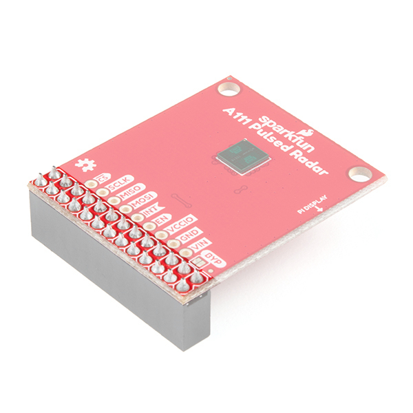
2x13 Female Header
To keep the size of the board small, there is a 2x13 female header soldered on the board to easily mate with a Raspberry Pi's standard header.
 |
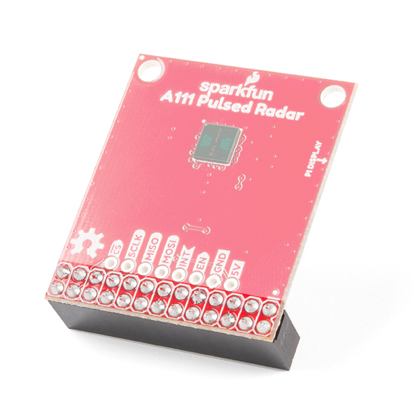 |
| HAT Standard Header with Female Connector v1.1 and v1.0 | |
This should only cover the part of the 2x20 male headers on the Pi. Regardless of the version number, the HAT will be stacked near the display port's ribbon cable connector.
 |
 |
| A111 HAT v1.1 and v1.0 Stacked on a Raspberry Pi | |
Additional Pins and Jumper Broken Out
Just above the 26-Pin header, there are additional pins broken out for SPI, interrupt, enable, and power if you need access to the pins. Note that in v1.1, the input voltage is labeled as VIN while 1.0 labels the pin as 5V. Both pins are connected to 5V of the Raspberry Pi's HAT standard pinout. For v1.1, the additional PTH for VCCIO is included between the enable and GND pin. For v1.1, additional pins are shifted and align with the 2x13 header.
 |
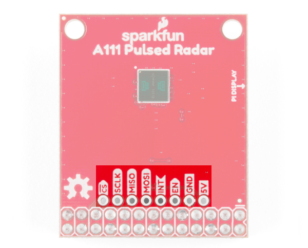 |
| Pins broken out on v1.1 and v1.0 | |
For v1.1, you'll also notice a bypass jumper (labeled as BYP). Adding a solder jumper to the board will set VCCIO to VIN.
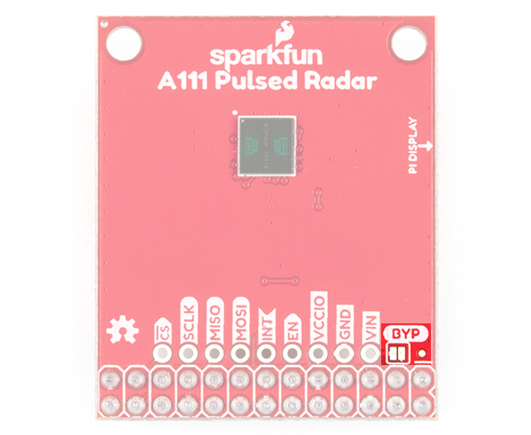
BYP pin will set VCCIO to VIN. If you are stacking the HAT on a Raspberry Pi, this will set the logic level on the Raspberry Pi's side to 5V.We recommend leaving this jumper alone when stacking the board on a Pi.
The A111 IC requires an input voltage of 1.8V, so a voltage regulator is populated on the back.
 |
 |
| Voltage Regulator on v1.1 and v1.0 | |
Additionally, the I/O logic level on the A111 is 1.8V, so a logic converter is included to translate the signals between the Raspberry Pi.
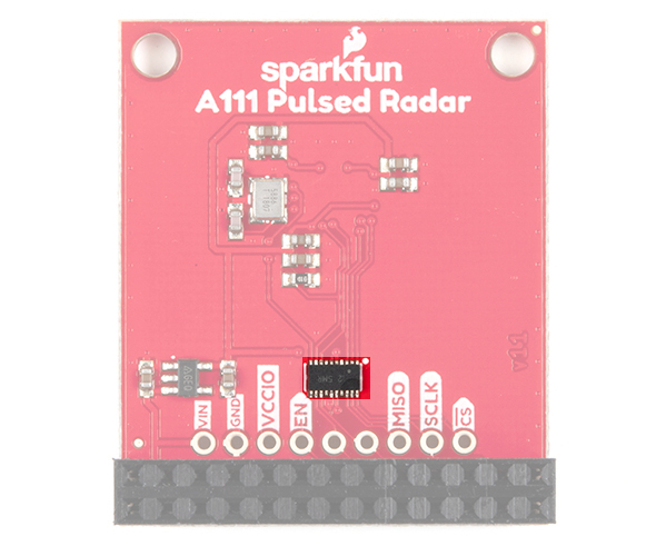 |
 |
| Logic Level Converter on v1.1 and v1.0 | |
Board Dimensions
The overall board size is 1.30in x 1.55in. There are two additional mounting holes spaced 0.10 inches away from the edge of the board.
 |
 |
| Board Dimensions for v1.1 and v1.0 | |
Hardware Assembly
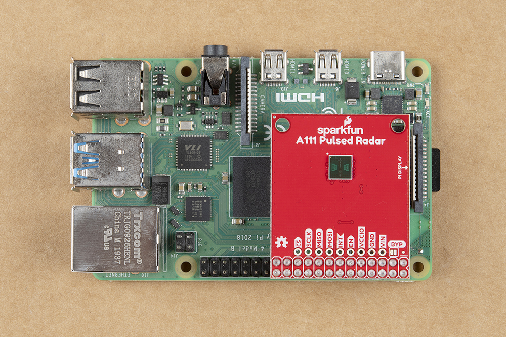
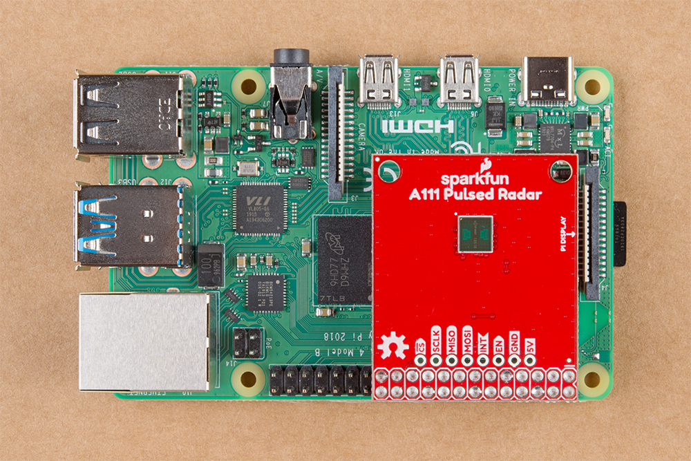
The A111 Pulsed Radar Breakout is designed to sit directly on top of a Raspberry Pi. Again, it doesn't span all 40 (2x20) pins of a Raspberry Pi B+ (or later), but the 26-pin — 2x13 — header should be compatible with any Pi.
Connect the shield to a Raspberry Pi ensuring that the "Pi Display" text on the breakout matches up with the display header on your Pi. The sensor should be facing up after plugging it in.
|
|
| A111 HAT v1.1 and v1.0 Stacked on a Raspberry Pi | |
Or, if you'd like to manually wire the breakout up to a Raspberry Pi's standard pinout, here is the pin-out we'll use through the rest of this tutorial. As stated in the hardware overview for v1.1, the input voltage is labeled as VIN while 1.0 labels the pin as 5V. Both pins are connected to 5V of the Raspberry Pi's HAT standard pinout. For v1.1, the additional PTH for VCCIO is included between the enable and GND pin.
| v1.1 Breakout Pin | v1.0 Breakout Pin | Raspberry Pi Pin Name | RasPi Hardware Pin Number |
|---|---|---|---|
| CS | CS | SPI0 CS0 | 24 |
| SCLK | SCLK | SPI0 SCLK | 23 |
| MISO | MISO | SPI0 MISO | 21 |
| MOSI | MOSI | SPI0 MOSI | 19 |
| INT | INT | GPIO25 | 22 |
| EN | EN | GPIO27 | 13 |
| VCCIO | 3.3V | 1, 17 | |
| GND | GND | GND | 6, 14, 20, etc. |
| VIN | 5V | 5V | 2, 4 |
When connecting to the additional pins broken out next to the Raspberry Pi's I/O, make sure to not accidentally connect anything higher than 3.3V since it is only 3.3V tolerant.
Configure Your Pi
Raspbian and SPI
This tutorial assumes you've already set up a Raspberry Pi with Raspbian. For help installing the Debian-based OS on your Pi, check out the docs on Raspberrypi.org. Or -- better yet! -- check out our Headless Raspberry Pi Setup tutorial.
You'll also need to enable SPI on your Pi. For help with that, check out our SPI on Pi tutorial.
We are going to assume you already have a Raspberry Pi up and running with Raspbian. We'll also assume that it is connected to the Internet. If not, check out our starter kits and tutorials on setting up a Raspberry Pi. We recommend looking at the following tutorials to get started. Overall, the setup is the same regardless of the version that you have.
Raspberry Pi 4 Kit Hookup Guide
Raspberry Pi 3 Starter Kit Hookup Guide
Make sure to update the image so that we have the latest distribution. Enter the following commands in the command line individually to update your image.
language:bash
sudo apt-get update
sudo apt-get dist-upgrade
sudo.User Configuration Settings
Once you are set up, I highly recommend changing your default login and password: (username: pi, password: raspberry). The Raspberry Pi Configuration tool is a quick way to change your password as well as setup the network, language, keyboard, etc. There are two methods to adjust the settings. You can use the GUI by heading to the Pi Start Menu > Preferences > Raspberry Pi Configuration > Interfaces. For the old school heads, you can also use the raspi-config tool by typing the following command using the command line and then go through the menus to update your information.
language:bash
sudo raspi-config
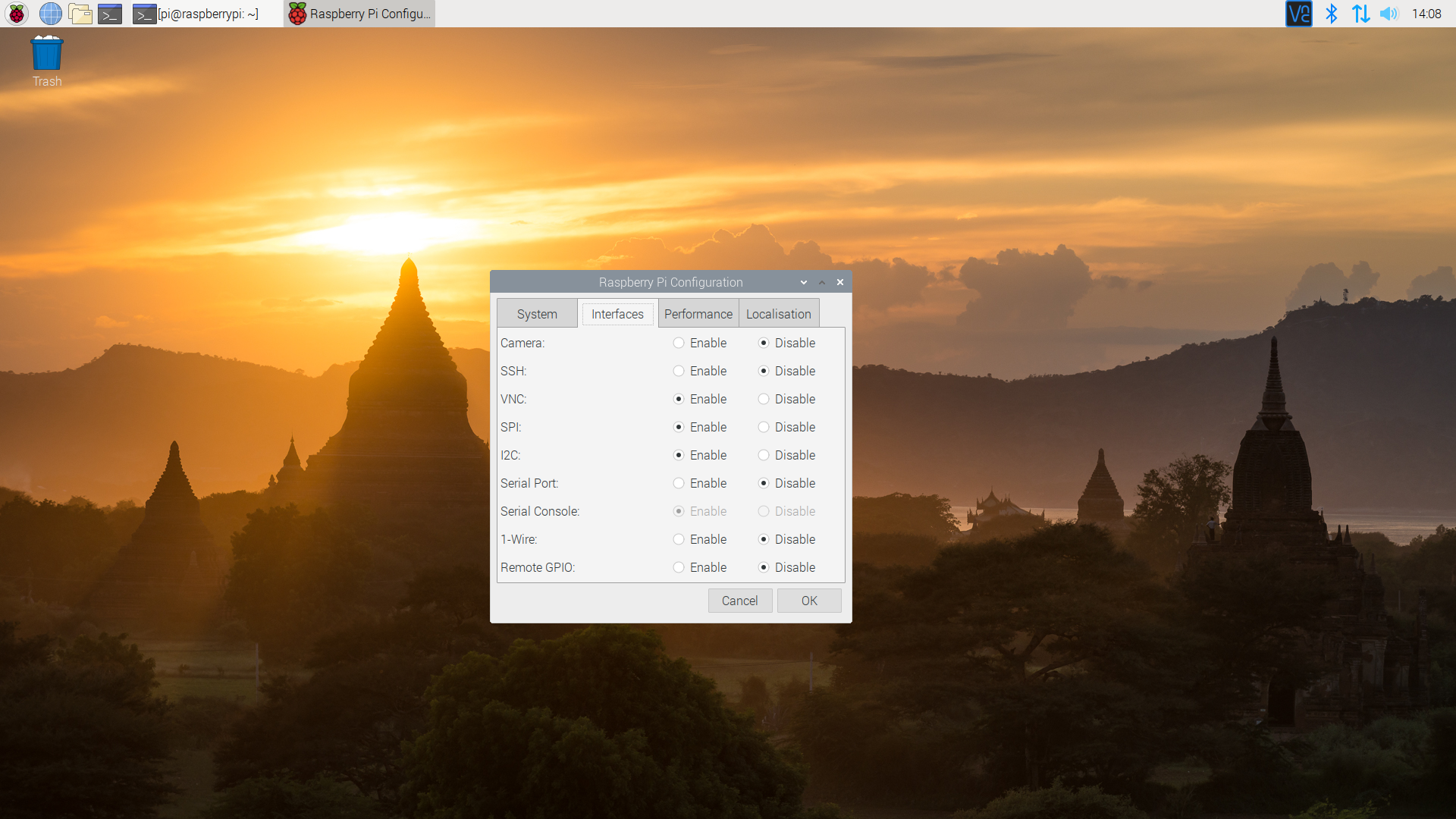
You'll want to enable the SPI pins using the tool to read sensor with SPI. If you are using hte GUI, simple select Enable and click on the OK button. If you are using the raspi-config, follow the prompts to finish setting up the SPI. For more information, check out our tutorial to set up the SPI pins on a Pi.
 |
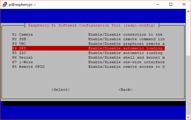 |
| Enabling SPI via Desktop GUI | raspi-config tool for SPI in the Terminal |
You'll need to restart your Pi for the changes to take effect.
Get the SDK
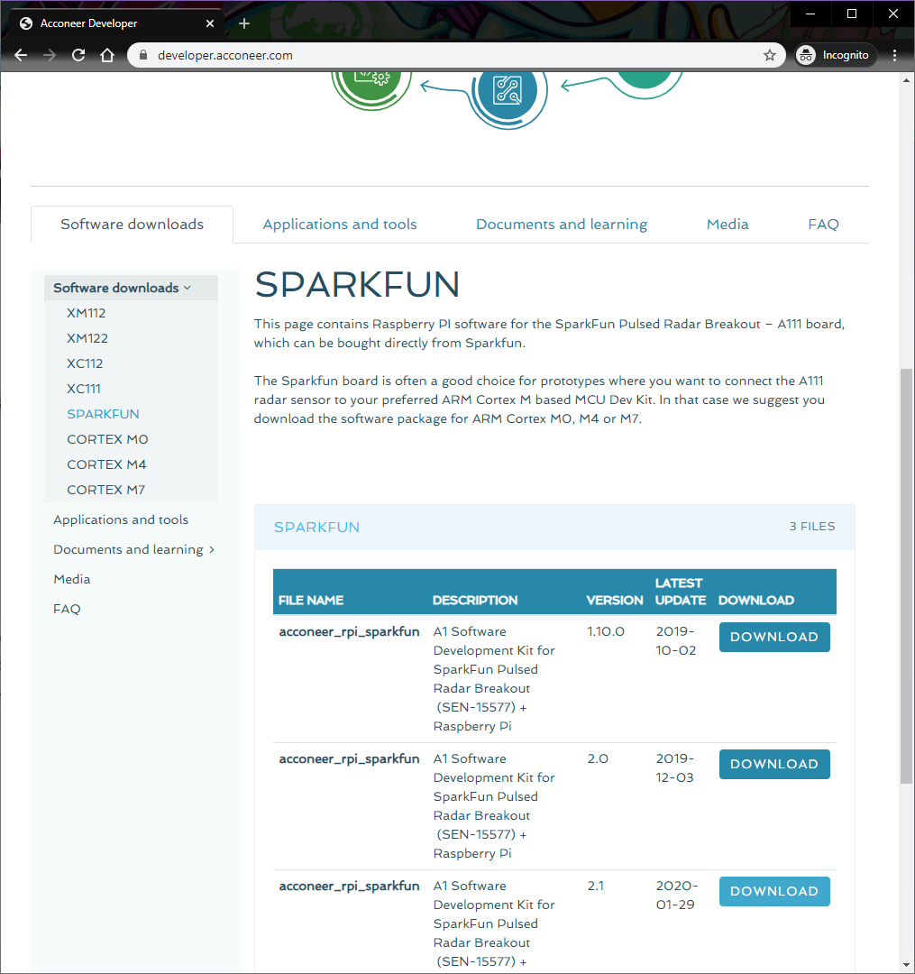
The software development kit (SDK) for the A111 is, unfortunately, locked behind a closed source blob that currently only supports Cortex-M4 and ARMv7 platforms. However, the folks over at Acconeer have agreed to host the latest version of their SDK with our example code from their website. To download the latest SDK from Acconeer, visit Acconeer's "Developer" page on your Raspberry Pi's browser.
You'll need an account in order to have access to the files. Click on the link at the bottom of the page to create one or log in. Or click on the shortcuts below.
Once you are logged in, the "Software Download" tab will include additional links to download the SDK. Scroll down the webpage to the section for the SPARKFUN. Acconeer is constantly updating and improving the software. We used v2.1 of the software when writing this tutorial so the version may be different from the version that you download. Click on the Download button for the latest version. In this case, it was v2.1.
Read through the license, agree, and click on the Download acconeer_rpi_sparkfun button for the software. Depending on your browser, you may need to refresh the page and repeat the directions before the button is active.
Once downloaded, head to directory where you downloaded the ZIP. You can use the GUI or you can use the terminal to unzip the SDK using the following commands (included are commands to install unzip). Just make sure to update the file name with the version that you downloaded. Assuming that you are in the Downloads folder, you will be using the following command in the Terminal.
language:bash
unzip acconeer_rpi_sparkfun_v2_1_0.zip
Then cd to the "rpi_sparkfun" directory to prepare to build the example software. Depending on the version that you downloaded, the path might be slightly different. Make sure to use the ls to verify the contents of the unzipped a111 folder if you have issues navigating through the directory.
SDK Overview
The A111 SDK includes source code, archived libraries, include files, and documentation for using the A111 pulsed radar sensor. Here's a quick overview of what's included with the SDK:
- doc — Doxygen-generated documentation for the A111 API and source code.
- include — Header and API files which describe how to interact with the pre-compiled A111 libraries.
- lib — Pre-compiled A111 static archives. API for these files are provided in the "include" directory.
- out — Compiled board and example object and executable files.
- rule — Recursive Makefile rules for board and example files.
- source — C source files for custom boards and example applications.
- makefile — Top-level makefile. Recursively calls files in the "rule" directory to build example and board files.
Build and Run the Test Sketch
In the terminal, executing the make file — and it's recursive dependencies — should build all of the examples you may use with the A111. To build all board and example files, navigate to the SDK's top-level directory (in this case, it should be similar to ...Downloads/rpi_sparkfun) where your makefile is located and type make or make all command in the terminal. You should see something similar to the output below.
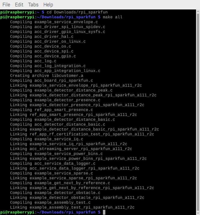
Troubleshooting
If you have any trouble building the board and example files, ensure that you have gcc and make packages installed. (E.g. apt-get install make gcc)
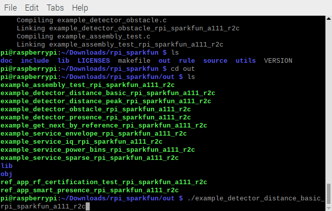
Running the Example Applications
Once compiled you can run the example applications. Navigate to the .../out folder with the cd in the terminal window. You can run the example by clicking on the executable or typing the following command. We recommend typing the command in the terminal to view the data. A few of the applications will automatically close the window after taking sensor data if you choose to click on the executable.
language:bash
./example_detector_distance_basic_rpi_sparkfun_a111_r2c
Once you type (or paste the command in the Terminal), hit Enter on your keyboard to execute the command.
This will run our modified distance-detector example application. For simplicity, it will show the distance of an object that is in front of the antennae.
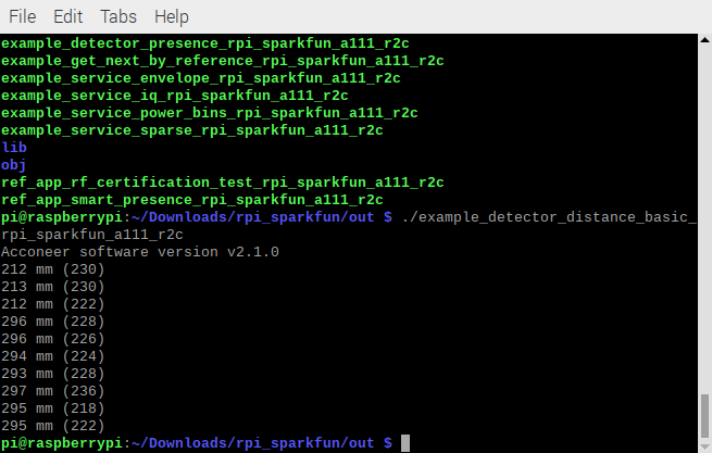
By placing an object in front of the sensor, the distance should vary based on what the A111 can detect. The application will continue running in the terminal window until the loop is finished. In this case, the example took 10 samples. Try adjusting the code to obtain more samples!
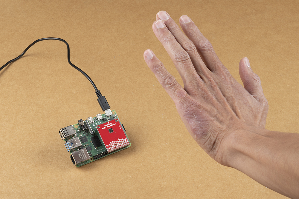 |
 |
| Hand placed in front the A111 v1.1 and v1.0 with the Pi remotely connected via VNC. | |
Running Other Examples
In addition to the distance detector basic, the SDK includes a few extra examples. To execute these files, run them from the out directory:
- example_detector_presence_rpi_sparkfun_a111_r2c — If there is an object moving in front of the sensor, it will output a true. Otherwise, the output is false.
- example_detector_obstacle_rpi_sparkfun_a111_r2c — Checks to see if there is an object in the way.
- example_service_iq_rpi_sparkfun_a111_r2c — Advanced version of the envelope service, which includes phase information for very small variations in distance. The output will be in polar coordinates.
- example_service_power_bins_rpi_sparkfun_a111_r2c — Demonstrates how to use A111 "power bins," which are still, kind of, a mystery to us...
- example_detector_distance_peak_rpi_sparkfun_a111_r2c — This application will begin by calculating raw peak-distances, with a maximum of ten reflections. The example will briefly estimate minimum and maximum threshold.
Make sure to read through the comments in the code (located in the source folder), datasheet, user guide, and associated documents from Acconeer for more information before writing your own custom code for the A111.
Troubleshooting
For the best support, we recommend checking the FAQ or submitting a support ticket with Acconeer since they handle the software SDK packages.
Resources and Going Further
Now that you've successfully got your A111 pulsed radar sensor up and running, it's time to incorporate it into your own project! For more information, check out the resources below:
- v1.1
- v1.0
- Acconeer
- Developer - SW Download, datasheet, user guide, FAQ
- Read the Docs: Setting Up Your Raspberry PI EVK - Documentation for the Python examples that might be useful in visualizing the data taken with the A111 examples.
- GitHub Repos
Need some inspiration for your next project? Check out some of these related tutorials: