ESP8266 Thing Hookup Guide
 jimblom
 Introduction
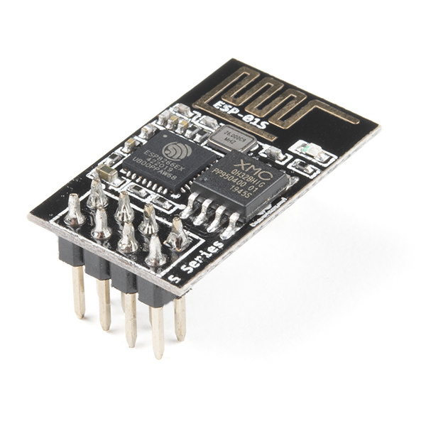
Over the past year, the ESP8266 has been a growing star among IoT or WiFi-related projects. It's an extremely cost-effective WiFi module, that -- with a little extra effort -- can be programmed just like any microcontroller. Unfortunately, the ESP8266 has mostly only been available in a tiny, modular form, which, with limited I/O and a funky pin-out, can be difficult to build a project around.
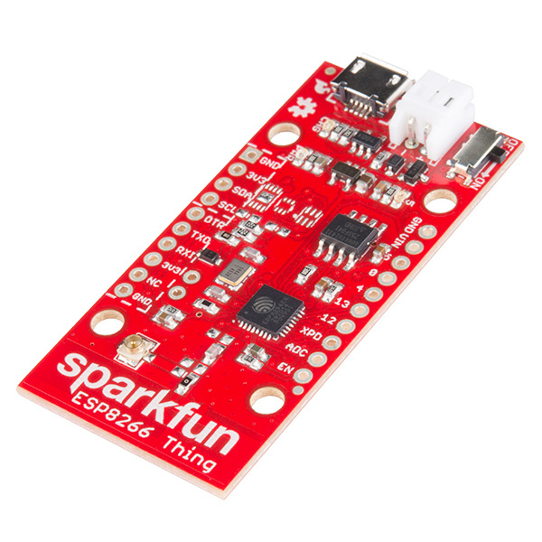
SparkFun's new development board for the ESP8266 breaks out all of the module's pins, and comes equipped with a LiPo charger, power supply, and all of the other supporting circuitry it requires. We lovingly call it the Thing -- it's the perfect foundation for your Internet of Things.
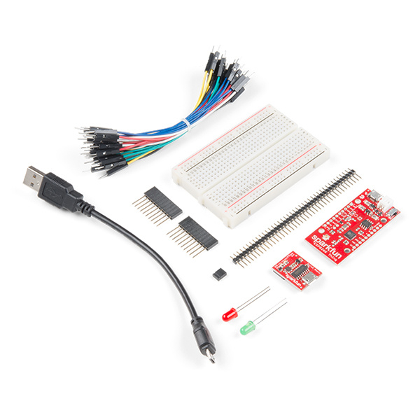
SparkFun ESP8266 Thing Starter Kit
KIT-15258Covered in this Tutorial
This tutorial will familiarize you with all things SparkFun Thing. It's split into sections, which cover:
- Hardware Overview -- A quick rundown of the Thing's components and pinout.
- Powering the Thing -- The Thing can be powered through either USB or a LiPo battery.
- Programming the Thing -- Interface a 3.3V FTDI Basic with the Thing to program it.
- Hardware Assembly -- Tips and recommendations on what to solder to the Thing's I/O pins.
- Installing the ESP8266 Arduino Addon -- The Thing can be programmed using Arduino! Just follow the instructions here to install the board definitions.
- Example Sketch: AP Web Server -- Set the Thing up as an access point and use it to serve web pages.
- Using the Arduino Addon -- There are a few key differences between programming the Thing and any other Arduino board.
Required Materials
To follow along with this tutorial, and get up-and-running with the Thing, you may need a few extra tools and materials. This wishlist includes everything we use in this tutorial to program and use the Thing if you are ordering the board individually:
Suggested Reading
Before continuing on with this tutorial, you may want to familiarize yourself with some of these topics if they're unfamiliar to you:
How to Solder: Through-Hole Soldering
Serial Communication
How to Power a Project
Logic Levels
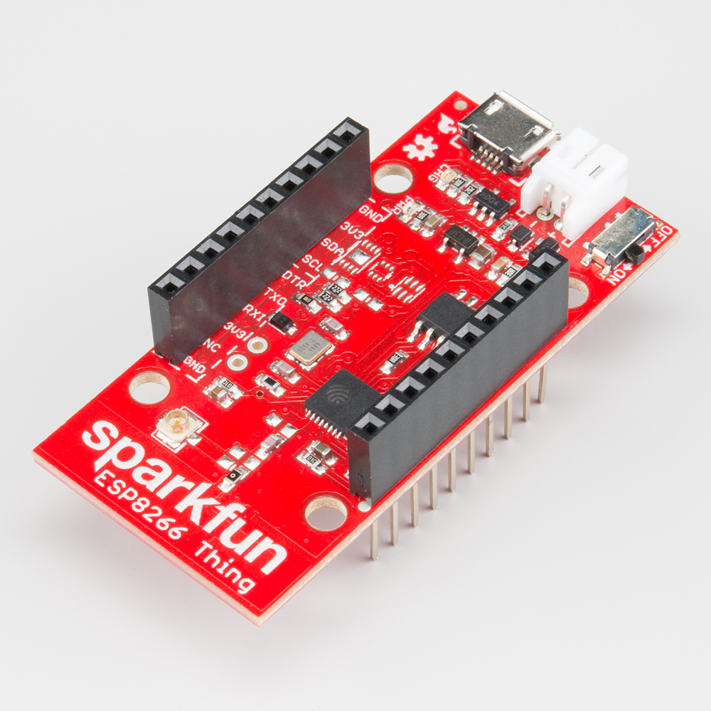
Hardware Overview
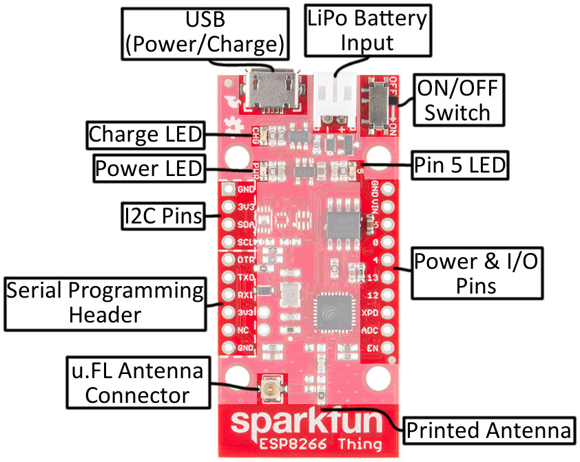
The ESP8266 Thing is a relatively simple board. The pins are broken out to two parallel, breadboard-compatible rows. USB and LiPo connectors at the top of the board provide power -- controlled by the nearby ON/OFF switch. And LEDs towards the inside of the board indicate power, charge, and status of the IC.
Here's a quick overview of the Thing's main components:
The Pinout
The Thing's I/O headers can be broken down into three sections:
Serial Programming Header
This six-pin header will be the main point of contact between the Thing and your development computer. The pinout of this header matches the extremely common "FTDI header." That means you can interface it with either a 3.3V FTDI Basic or a 3.3V I/O FTDI Cable to program and debug the Thing.
For a quick breakdown of the pins on this header, consult the table below. If a pin is directly tied to an ESP8266 I/O, it'll be noted:
| Pin Label | ESP8266 I/O # | Notes |
|---|---|---|
| DTR | Performs auto-reset, and puts the ESP8266 into bootloader mode. Connects through a capacitor to RESET, and a buffer to the ESP8266's GPIO0. | |
| TXO | 7 | ESP8266 UART1 data output. |
| RXI | 8 | ESP8266 UART1 data input. |
| 3V3 | By default, this pin does not supply the ESP8266 directly (a jumper on the back can change that). | |
| NC | Not connected to anything on the Thing. | |
| GND | Ground (0V). |
I2C Header
I2C is a very popular communication protocol in the embedded world. Whether you want to hook the Thing up to a motion sensor, light sensor, digital-to-analog converter, or OLED display, I2C is often the protocol of choice.
This header includes four pins -- all that should be required to connect an I2C device up to the Thing.
| Pin Label | ESP8266 I/O # | Notes |
|---|---|---|
| GND | Ground (0V). | |
| 3V3 | 3.3V | |
| SDA | 2 | Can either be used as ESP8266 GPIO2 or I2C serial data (SDA). |
| SCL | 14 | Can either be used as ESP8266 GPIO14 or I2C serial clock (SCL). Also used as the SPI clock (SCLK). |
This pinout matches that of most of our I2C-based breakout boards, so you can piggyback them right on top of the Thing.
If you need the extra I/O, instead of I2C, the SDA and SCL pins can be used as GPIO 2 and 14 respectively. The SCL pin also serves as the clock (SCLK) for the ESP8266's SPI interface.
General I/O Header
The rest of the power, control, and I/O pins are broken out on the other side of the board. They are:
| Pin Label | ESP8266 I/O # | Notes |
|---|---|---|
| GND | Ground (0V). | |
| VIN | USB connected: ~4.5V output LiPo connected (no USB): ~3.7V output No supply: Can be used as a voltage supply input to the 3.3V regulator. | |
| 5 | 5 | This pin is also tied to the on-board LED. |
| 0 | 0 | |
| 4 | 4 | |
| 13 | 13 | Hardware SPI MOSI |
| 12 | 12 | Hardware SPI MISO |
| XPD | 16 | Can be connected to reset to set the ESP8266 into deep sleep mode. |
| ADC | A0 | A 10-bit ADC with a maximum voltage of 1V. |
| EN | ESP8266 enable pin. HIGH = on, LOW = off. Pulled HIGH on-board. |
What happened to the rest of the GPIO pins? Why the eclectic pin-numbering scheme? We're taking what the ESP8266 gives us. Unfortunately, most of the remaining GPIO are connected to the on-board SPI flash memory IC, which stores the ESP8266's program memory and potentially other data.
Back of the Thing
Flipping the Thing over revels a few trace jumpers and test points, which you may find handy for your application.
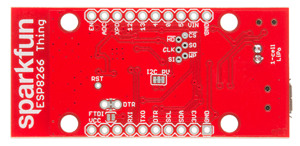
Jumpers
| Jumper Label | Default Setting | Notes |
|---|---|---|
| DTR | Closed | Allows for auto-reset while programming the ESP8266, but makes serial debugging difficult. |
| I2C PU | Closed | Connects 10kΩ pull-up resistors to the SDA and SCL pins. |
| FTDI VCC | Open | Connects the 3V3 pin on the serial header directly to the ESP8266's 3.3V supply. |
Of these jumpers, the DTR one is the most commonly modified. The DTR output of the FTDI Basic is used for two purposes: to reset the ESP8266 and pull GPIO0 low (putting the chip in bootloader mode). Keeping this jumper closed enables programming, but makes debugging via the Serial Monitor difficult, as the board will reset into bootloader mode whenever the terminal opens. Using and modifying this jumper is discussed later in this tutorial.
The FTDI_VCC jumper defaults to open to ensure that, if a 3.3V Logic (5V power) FTDI Cable is used to program the Thing, 5V isn't accidentally delivered to the IC. Also, most 3.3V FTDI boards don't have a lot of juice to supply on the 3.3V bus (they often supply about 50mA max).
Test Points
These pins are made available just in case they become necessary to your project. The six pins bundled up together are connected to the Thing's on-board SPI flash memory, but if you really need the extra GPIO, or want to experiment with the pins, they're available.
The RST pin is more useful, but we didn't leave room to break it out -- at least not directly. RST is tied through a 0.1µF capacitor to the DTR pin, to allow for automatic reset during programming. For many applications that need the RST pin, toggling the DTR pin works as well. Putting the ESP8266 into deep sleep is one such application.
Selecting the Antenna
The Thing's default WiFi antenna is a PCB trace antenna based on this TI app note. It's cost-effective and actually works really well!
If you need to connect a more sensitive antenna to the chip, a U.FL connector is also available on the board, but isn't connected by default to the ESP8266's antenna pin. To connect this antenna to the chip, you'll need to heat up the 0Ω resistor and rotate it 90°:

A soldering iron, pair of tweezers, (2) steady hands, and good set of eyes should be enough to accomplish the task.
Why Are There Unpopulated Parts?
We initially set out to make the Thing a secure, common-sensor base station. The empty pads you see are landing spots for three unique IC's:
- ATECC108A -- A "full turnkey Elliptic Curve Digital Signature Algorithm (ECDSA) engine", which can be used for unique serial numbers, hashing, key storage, or random numbers. A great start to securing your IoT project!
- TMP102 Temperature Sensor -- A simple, 12-bit, digital temperature sensor.
- TSL2561 Light Sensor -- A nifty luminosity/light sensor. If you are lucky to have obtained this sensor, the spot is available to populate. Unfortunately, the TSL2561 sensor is EOL so you will need to opt to use a different light sensor and connect via the the PTH along the sides of the board.
- Plus a few footprints for decoupling capacitors.
After a late change of heart, we decided to keep the board as low cost as possible (that's the ESP8266's best feature!), while leaving the option for later expansion. The pads are still there. If you want to add any of these components, hopefully all you should need is a hot air station (maybe probably not a Heaterizer) and some tweezers.
Powering the Thing
The Thing provides for two methods of power delivery: USB or LiPo. The USB connector on the Thing is of the Micro-B variety. A micro-B cable plugged into either a computer USB port or a 5V USB Wall Wart can power the Thing.
Any of our single-cell LiPo batteries will also work to power the Thing -- they all have the same 2-pin JST connector.
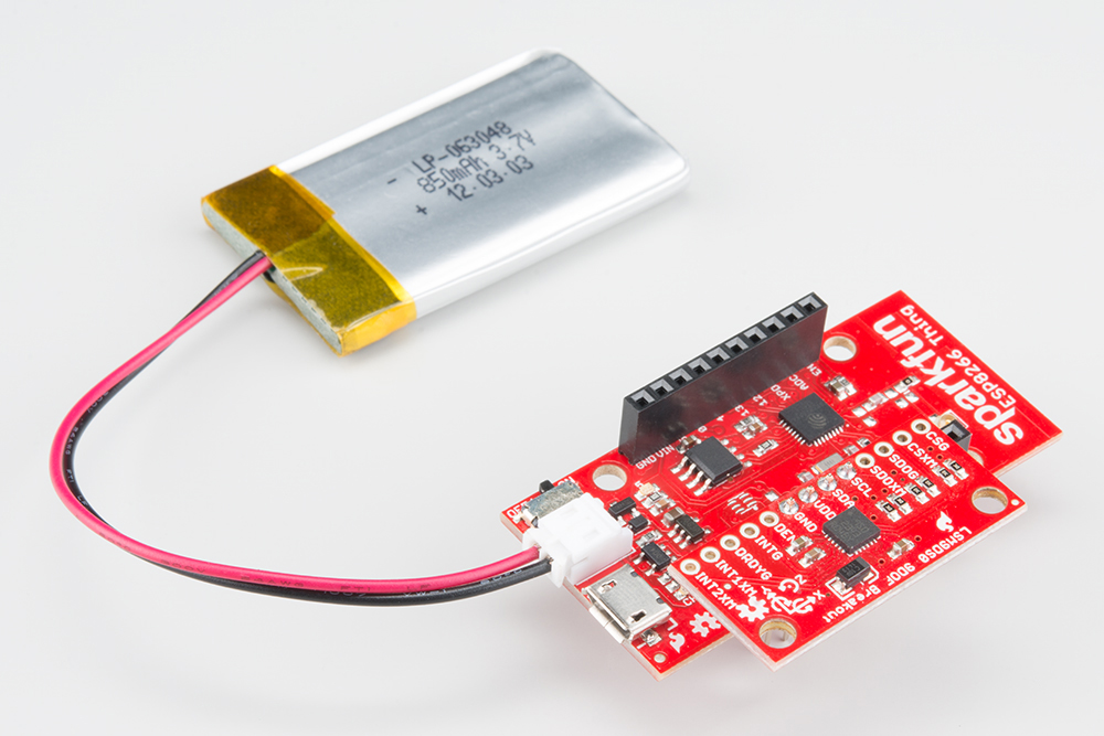
If both USB and LiPo are connected to the Thing, it'll take power from the USB port and charge the LiPo battery at up to 500mA.
Electrical Characteristics
The ESP8266's maximum voltage is 3.6V, so the Thing has an onboard 3.3V regulator to deliver a safe, consistent voltage to the IC. That means the ESP8266's I/O pins also run at 3.3V, you'll need to level shift any 5V signals running into the IC.
The input to this regulator can either be delivered by USB, LiPo battery, or through the VIN pin.
Alternatively, if you have an external, regulated, supply you'd like to deliver directly to the ESP8266, you can supply that voltage through the 3V3 pin (on the I2C header). While this voltage doesn't have to be 3.3V, it must be within the range of 1.7-3.6V.
Current Ratings
On average, the Thing pulls about 80mA. WiFi transmits and receives can momentarily increase that draw. Here's a table, transcribed from the ESP8266 datasheet, with some of the more common current characteristics.
| Parameter | Typical | Max | Unit |
|---|---|---|---|
| Transmit 802.11b (1 Mbps) | 215 | mA | |
| Transmit 802.11b (11 Mbps) | 197 | mA | |
| Transmit 802.11g (54 Mbps) | 145 | mA | |
| Transmit 802.11n | 135 | mA | |
| Receive 802.11b | 60 | mA | |
| Receive 802.11g | 60 | mA | |
| Receive 802.11n | 62 | mA | |
| Standby | 0.9 | mA | |
| Deep Sleep | 10 | µA | |
| Maximum I/O Pin Drive Capability | 12 | mA |
If your application requires maximum battery life, you'll likely need to make liberal use of the ESP8266's deep sleep functionality. That'll be covered later in this tutorial.
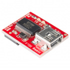
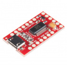
Programming the Thing
The ESP8266 has a built-in serial bootloader, which allows for easy programming and re-programming. You don't need a specialized, expensive programmer -- just a simple, USB-to-Serial converter. We use a 3.3V FTDI Basic to program the Thing, but other serial converters with 3.3V I/O levels should work (e.g. FT231X Breakout, CH340G Basic Breakout). Just make sure to install the respective drivers for your converter and get the compatible USB cable. The converter does need a DTR line in addition to the RX and TX pins.
Depending on your setup, there is a few methods of programming the ESP8266 Thing. Below are a few ways to program the ESP8266 Thing using a serial-to-USB converter.
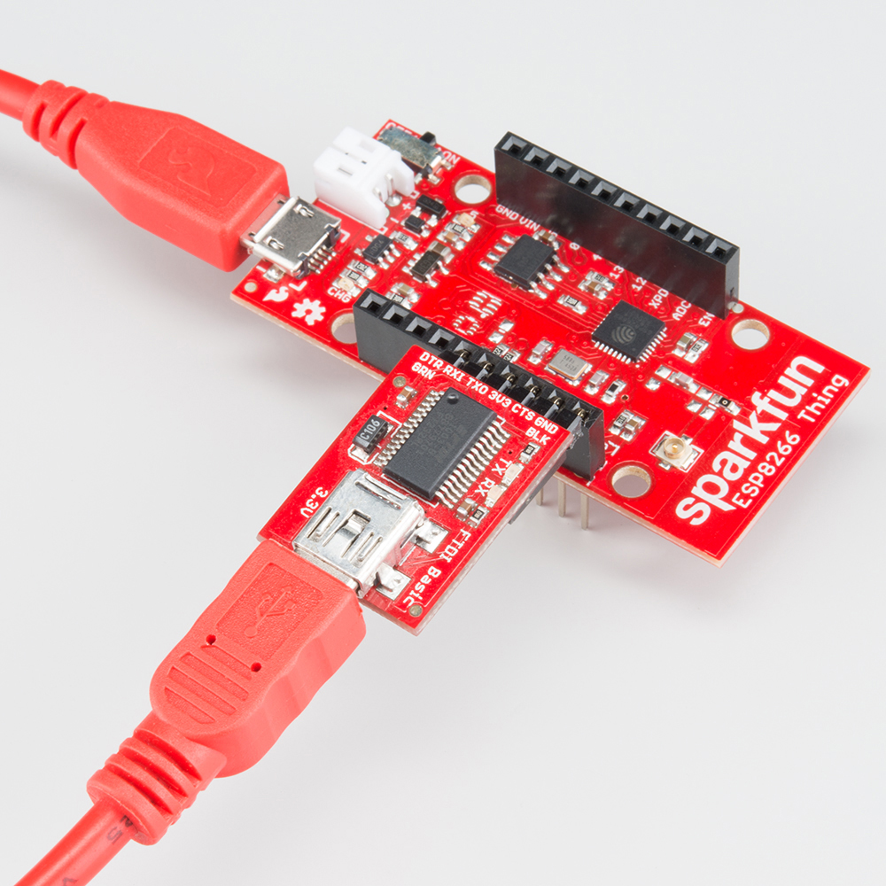
Method 1: Two USB Cables
The FTDI Basic's 6-pin header matches up exactly to the Thing's 6-pin serial port header. To set up for programming, simply connect the FTDI directly to this port -- take care to match up the DTR and GND pins! If you solder female headers to the Thing, plugging a 6-pin row of right-angle male headers between the FTDI and header helps create a temporary programming interface. The header pins are small on one side, so make sure that there is contact between the two boards while uploading.
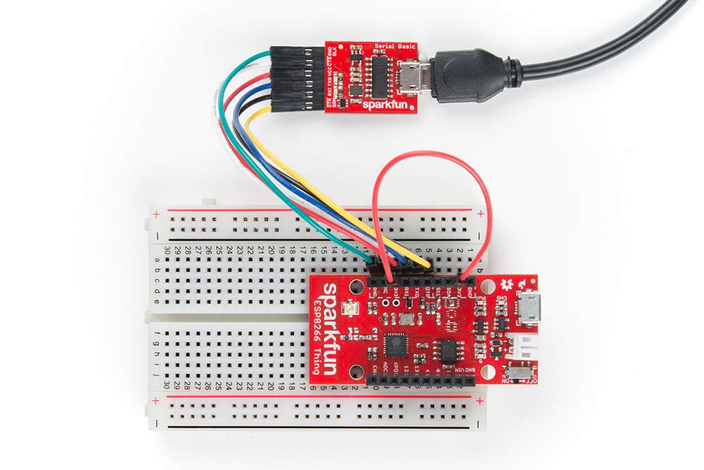
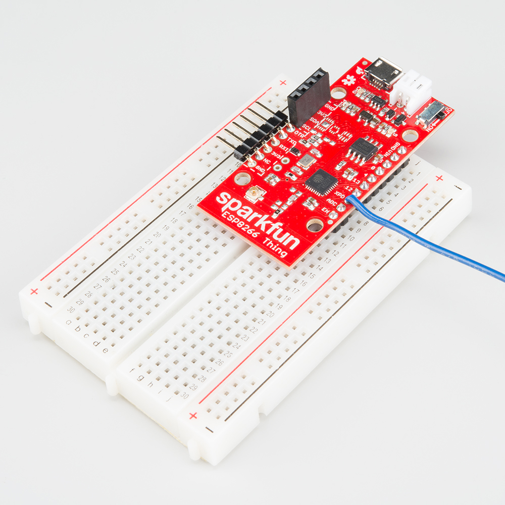
Method 2: One USB Cable with Jumper Wire
If you only have one USB cable, you can connect a USB-to-serial converter to the ESP8266 Thing's serial programming header. You will just need to connect 3V3 on the serial programming header side to the 3V3 on the I2C header together with a jumper wire. Below is an example of the CH340G serial basic connected with the jumper wire connecting the 3.3V pins.
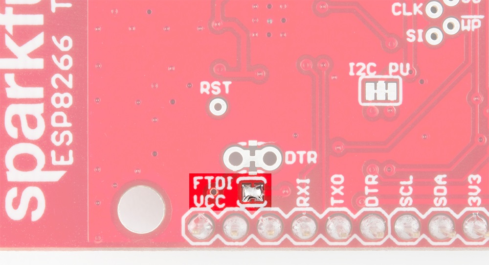
Method 3: One USB Cable with Solder Jumper
A third method is to add a solder jumper to the jumper pads labeled as "FTDI VCC" to connect the 3V3 pins together between the serial programming header and the I2C header. You can then connect a USB-to-serial converter to the serial programming header as stated earlier.
Hardware Assembly
Oh. We're getting ahead of ourselves. To connect the FTDI programmer to your Thing you'll need to solder something to the Thing.
If you've never soldered before, this is a great time to start! These solder points are easy, through-hole pins, check out our How to Solder - Through-hole Soldering for help getting started.
What, exactly, you solder to the board depends both on how you'll use it in your project, and how you'll interface it with the programmer. When it comes to selecting a header (or wire) to solder, there are a variety of options. We've tried a lot of them with the Thing:
10-pin Stackable Headers make it convenient to both breadboard the Thing and jumper wire out of it.
Or you can mix and match headers to best fit your needs. Right-angle male headers may help to interface between the FTDI and the Thing. Straight male headers are a good choice for low-profile connections. Straight female headers may help with connecting to I2C sensors. And, of course, wire can be soldered to any of the pins that have a long way to connect to something.
Once you've soldered up at least the programming port, you're ready to load some code onto the Thing. Let's blink some LEDs and IoT (Internet our Thing).
Installing the ESP8266 Arduino Addon
There are a variety of development environments that can be equipped to program the ESP8266. You can go with a simple Notepad/gcc setup, or fine-tune an Eclipse environment, use a virtual machine provided by Espressif, or come up with something of your own.
Fortunately, the amazing ESP8266 community recently took the IDE selection a step further by creating an Arduino addon. If you're just getting started programming the ESP8266, this is the environment we recommend beginning with, and the one we'll document in this tutorial.
This ESP8266 addon for Arduino is based on the amazing work by Ivan Grokhotkov and the rest of the ESP8266 community. Check out the ESP8266 Arduino GitHub repository for more information.
Installing the Addon With the Arduino Boards Manager
With the release of Arduino 1.6.4, adding third party boards to the Arduino IDE is easily achieved through the new board manager. If you're running an older version of Arduino (1.6.3 or earlier), we recommend upgrading now. As always, you can download the latest version of Arduino from Arduino.cc.
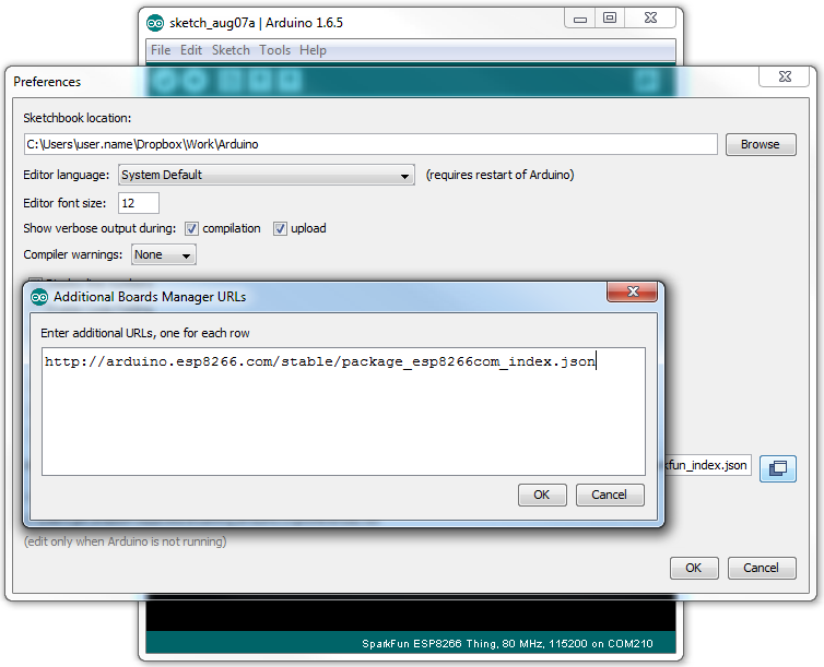
To begin, we'll need to update the board manager with a custom URL. Open up Arduino, then go to the Preferences (File > Preferences). Then, towards the bottom of the window, copy this URL into the "Additional Board Manager URLs" text box:
http://arduino.esp8266.com/stable/package_esp8266com_index.json
If you already have a URL in there, and want to keep it, you can separate multiple URLs by placing a comma between them. (Arduino 1.6.5 added an expanded text box, separate links in here by line.)
Hit OK. Then navigate to the Board Manager by going to Tools > Boards > Boards Manager. There should be a couple new entries in addition to the standard Arduino boards. Look for esp8266. Click on that entry, then select Install.
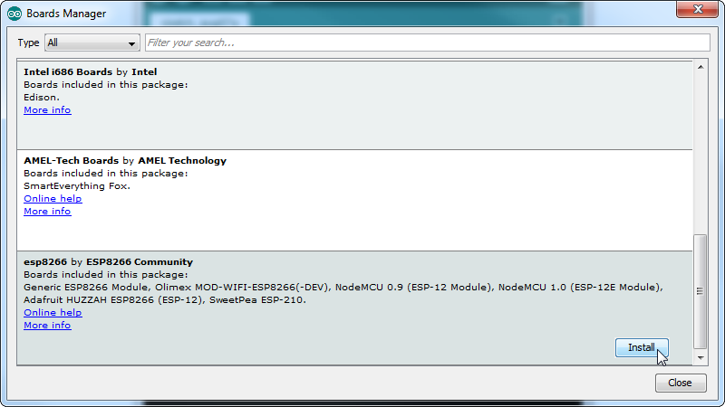
The board definitions and tools for the ESP8266 Thing include a whole new set of gcc, g++, and other reasonably large, compiled binaries, so it may take a few minutes to download and install (the archived file is ~110MB). Once the installation has completed, an Arduino-blue "INSTALLED" will appear next to the entry.
Selecting the ESP8266 Thing Board
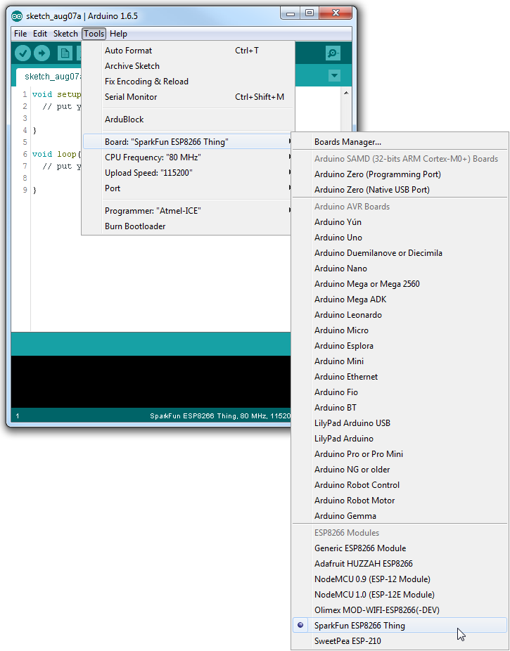
With the Board addon installed, all that's left to do is select "ESP8266 Thing" from the Tools > Boards menu.
Then select your FTDI's port number under the Tools > Port menu.
Example Sketch: Blink
To verify that everything works, try uploading the old standard: Blink. Instead of blinking pin 13, like you may be used to though, toggle pin 5, which is attached to the onboard LED.
language:c
#define ESP8266_LED 5

void setup()
{
  pinMode(ESP8266_LED, OUTPUT);
}

void loop()
{
  digitalWrite(ESP8266_LED, HIGH);
  delay(500);
  digitalWrite(ESP8266_LED, LOW);
  delay(500);
}
If the upload fails, first make sure the ESP8266 Thing is turned on -- the red "PWR" LED should be illuminated.
Faster Uploads! The serial upload speed defaults to 115200 bps, which is reliable, but can feel a bit slow. You can increase the upload speed by a factor of about 8 by selecting 921600 under the Tools > Upload Speed menu.
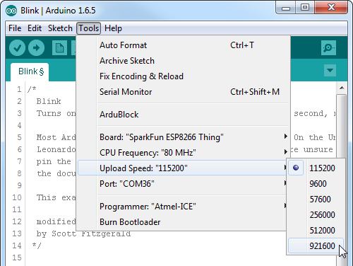
This faster upload speed can be slightly less reliable, but will save you loads of time!
There are still some bugs to be fleshed out of the esptool, sometimes it may take a couple tries to successfully upload a sketch. If you continue to fail, try turning the ESP8266 Thing on then off, or unplug then replug the FTDI in. If you still have trouble, get in touch with our amazing tech support team.
Example Sketch: AP Web Server
Not only can the ESP8266 connect to a WiFi network and interact with the Internet, but it can also set up a network of its own, allowing other devices to connect directly to it. This example demonstrates how to turn the ESP8266 into an access point (AP), and serve up web pages to any connected client.
Copy and paste the code from below in the Arduino IDE. Then hit the upload button.
language:c
#include <ESP8266WiFi.h>

//////////////////////
// WiFi Definitions //
//////////////////////
const char WiFiAPPSK[] = "sparkfun";

/////////////////////
// Pin Definitions //
/////////////////////
const int LED_PIN = 5; // Thing's onboard, green LED
const int ANALOG_PIN = A0; // The only analog pin on the Thing
const int DIGITAL_PIN = 12; // Digital pin to be read

WiFiServer server(80);

void setup()
{
  initHardware();
  setupWiFi();
  server.begin();
}

void loop()
{
  // Check if a client has connected
  WiFiClient client = server.available();
  if (!client) {
    return;
  }

  // Read the first line of the request
  String req = client.readStringUntil('\r');
  Serial.println(req);
  client.flush();

  // Match the request
  int val = -1; // We'll use 'val' to keep track of both the
                // request type (read/set) and value if set.
  if (req.indexOf("/led/0") != -1)
    val = 0; // Will write LED low
  else if (req.indexOf("/led/1") != -1)
    val = 1; // Will write LED high
  else if (req.indexOf("/read") != -1)
    val = -2; // Will print pin reads
  // Otherwise request will be invalid. We'll say as much in HTML

  // Set GPIO5 according to the request
  if (val >= 0)
    digitalWrite(LED_PIN, val);

  client.flush();

  // Prepare the response. Start with the common header:
  String s = "HTTP/1.1 200 OK\r\n";
  s += "Content-Type: text/html\r\n\r\n";
  s += "<!DOCTYPE HTML>\r\n<html>\r\n";

  /*Note: Uncomment the line below to refresh automatically
   *      for every 1 second. This is not ideal for large pages
   *      but for a simple read out, it is useful for monitoring
   *      your sensors and I/O pins. To adjust the fresh rate,
   *      adjust the value for content. For 30 seconds, simply
   *      change the value to 30.*/
  //s += "<meta http-equiv='refresh' content='1'/>\r\n";//auto refresh page

  // If we're setting the LED, print out a message saying we did
  if (val >= 0)
  {
    s += "LED is now ";
    s += (val)?"on":"off";
  }
  else if (val == -2)
  { // If we're reading pins, print out those values:
    s += "Analog Pin = ";
    s += String(analogRead(ANALOG_PIN));
    s += "<br>"; // Go to the next line.
    s += "Digital Pin 12 = ";
    s += String(digitalRead(DIGITAL_PIN));
  }
  else
  {
    s += "Invalid Request.<br> Try /led/1, /led/0, or /read.";
  }
  s += "</html>\n";

  // Send the response to the client
  client.print(s);
  delay(1);
  Serial.println("Client disonnected");

  // The client will actually be disconnected
  // when the function returns and 'client' object is detroyed
}

void setupWiFi()
{
  WiFi.mode(WIFI_AP);

  // Do a little work to get a unique-ish name. Append the
  // last two bytes of the MAC (HEX'd) to "Thing-":
  uint8_t mac[WL_MAC_ADDR_LENGTH];
  WiFi.softAPmacAddress(mac);
  String macID = String(mac[WL_MAC_ADDR_LENGTH - 2], HEX) +
                 String(mac[WL_MAC_ADDR_LENGTH - 1], HEX);
  macID.toUpperCase();
  String AP_NameString = "ESP8266 Thing " + macID;

  char AP_NameChar[AP_NameString.length() + 1];
  memset(AP_NameChar, 0, AP_NameString.length() + 1);

  for (int i=0; i<AP_NameString.length(); i++)
    AP_NameChar[i] = AP_NameString.charAt(i);

  WiFi.softAP(AP_NameChar, WiFiAPPSK);
}

void initHardware()
{
  Serial.begin(115200);
  pinMode(DIGITAL_PIN, INPUT_PULLUP);
  pinMode(LED_PIN, OUTPUT);
  digitalWrite(LED_PIN, LOW);
  // Don't need to set ANALOG_PIN as input,
  // that's all it can be.
}
After uploading this sketch, find another device that you can connect to a WiFi network -- phone, laptop, etc. Look for a network called "Thing-XXXX", where XXXX is the last 2 bytes of the Thing's MAC address.
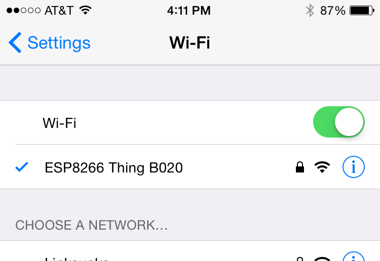
The sketch sets the network's password to "sparkfun".
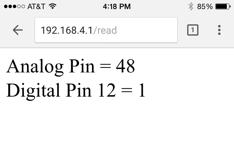
After connecting to your Thing's AP network, load up a browser and point it to 192.168.4.1/read. The Thing should serve up a web page showing you its ADC and digital pin 12 readings:
After that, give 192.168.4.1/led/0 and 192.168.4.1/led/1 a try, and keep an eye on the Thing's green LED while you do.
Auto Refresh
Tired of hitting the refresh button to update the I/O pin readings? Try uncommenting the line of code where it says: s += "<meta http-equiv='refresh' content='1'/>\r\n";. Then reupload the code to your ESP8266. This line of code will auto refresh the page every second.
  /*Note: Uncomment the line below to refresh automatically
   *      for every 1 second. This is not ideal for large pages
   *      but for a simple read out, it is useful for monitoring
   *      your sensors and I/O pins. To adjust the fresh rate,
   *      adjust the value for content. For 30 seconds, simply
   *      change the value to 30.*/
  //s += "<meta http-equiv='refresh' content='1'/>\r\n";//auto refresh page
As always, check through the code comments to get a line-by-line breakdown of what's going on.
Using the Arduino Addon
If you've used Arduino in the past, there will be some new programming schemes to get used to in ESP8266 land.
Pin Mappings
As with any other Arduino, the pin mappings printed on the board match the pin you read or write to. The SDA and SCL pins can be referenced as 2 and 14 respectively.
There's only one analog input pin, labeled ADC. To read the ADC pin, make a function call to analogRead(A0). Remember that this pin has a weird maximum voltage of 1V -- you'll get a 10-bit value (0-1023) proportional to a voltage between 0 and 1V.
Yielding
This is one of the most critical differences between the ESP8266 and a more classical Arduino microcontroller. The ESP8266 runs a lot of utility functions in the background -- keeping WiFi connected, managing the TCP/IP stack, and performing other duties. Blocking these functions from running can cause the ESP8266 to crash and reset itself. To avoid these mysterious resets, avoid long, blocking loops in your sketch.
If you have a long loop in your sketch, you can add a delay([milliseconds]) call within, to allow the critical background functions to execute. The ESP8266's delay() funciton, while of course delaying for a set number of milliseconds, also makes a quick call to the background functions.
The amazing creators of the ESP8266 Arduino libraries also implemented a yield() function, which calls on the background functions to allow them to do their thing. As an example, if your sketch is waiting for someone to press a button attached to pin 12, creating a loop like this will keep the ESP8266 from crashing:
language:c
pinMode(12, INPUT_PULLUP); // Set pin 12 as an input w/ pull-up
while (digitalRead(12) == HIGH) // While pin 12 is HIGH (not activated)
    yield(); // Do (almost) nothing -- yield to allow ESP8266 background functions
Serial.println("Button is pressed!"); // Print button pressed message.
ESP8266WiFi Class
This is the ESP8266, so the WiFi class will probably be included in just about every sketch there is. If you've used the Arduino WiFi library before, the ESP8266 WiFi library will be very similar, there's just a few key differences:
- To include the ESP8266 WiFi library call
#include <ESP8266WiFi.h>not<WiFi.h>. - To connect to a network, like the normal WiFi library, call
WiFi.begin(NetworkSSID, NetworkPassword). You can also set the ESP8266 up as a WiFi access point by callingWiFi.softAP(AP_SSID, AP_Password). - To set the ESP8266's mode, which can be access point (AP), station (STA), or combo (the ESP8266 can do both at the same time!), call
WiFi.setMode([mode])with eitherWIFI_AP,WIFI_STA, orWIFI_STA_APas the parameter.
The examples earlier in this tutorial should have demonstrated all of these differences.
Libraries Available/Not Available and the Differences
A lot of the core Arduino libraries have been re-written to work for the ESP8266, including:
- Wire -- The ESP8266 should work with any I2C sensor you can throw at it -- just use the same Wire API calls you're used to. There are a few differences:
- Pin definition: The ESP2866 doesn't actually have any hardware I2C pins -- those labeled on the Thing are the default, but you can actually use any two pins as SDA and SCL. Calling
Wire.begin()will assume pins 2 and 14 are SDA and SCL, but you can manually set them to any other pin by callingWire.begin([SDA], [SCL]).
- Pin definition: The ESP2866 doesn't actually have any hardware I2C pins -- those labeled on the Thing are the default, but you can actually use any two pins as SDA and SCL. Calling
- SPI -- The ESP8266 Thing can control an SPI bus using function calls made standard by the Arduino SPI library.
- An additional function to set the frequency --
SPI.setFrequency([frequency])-- is added. You may need to call that in your setup to slow the clock down from its default value. For example,SPI.setFrequency(1000000)will set the SPI clock to 1MHz. - The MISO, MOSI, and SCLK SPI pins are hard-coded and can't be moved, they are:
- An additional function to set the frequency --
| Pin Number | SPI Function |
|---|---|
| 12 | MISO |
| 13 | MOSI |
| 14 (SCL) | SCLK |
| 15 | CS |
Using the Serial Monitor
GPIO0 -- while perfectly capable as a digital I/O -- serves a secondary purpose as a bootload/run-mode controller. When the ESP8266 boots up, it looks at GPIO0's value to either enter the bootloader or start running the current program:
| GPIO0 Value | ESP8266 Mode |
|---|---|
| HIGH (3.3V) | Run Program |
| LOW (0V) | Bootloader |
To make it easy to program the ESP8266, we've tied GPIO0 to DTR (along with RST). When your programmer begins to upload a sketch, it'll pull DTR low, in turn setting GPIO0 low and making the ESP8266 enter bootloader mode.
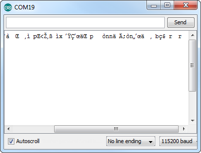
Unfortunately, when you open a serial terminal, DTR usually goes low again. So every time you open the Arduino serial monitor, it'll cause the ESP8266 to enter bootloader mode, instead of run-program mode. If you open up the serial monitor, and all you see is a line of gibberish, you've probably booted the ESP8266 into bootloader mode.
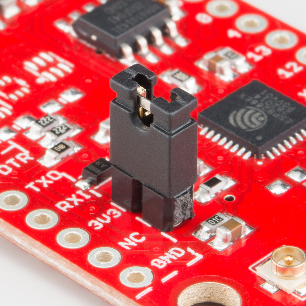
There are a few ways around this. We've added the DTR jumper on the bottom of the board. You can cut the trace on the back and install a 2-pin male header combined with a 2-pin jumper. If the jumper is present, the board will be able to be programmed. Removing the jumper will enable serial terminal mode.
Or you can find a serial terminal program that allows control of the DTR pin directly. RealTerm allows for this control -- navigate to the "Pins" tab, and click "Clear" next to "DTR."
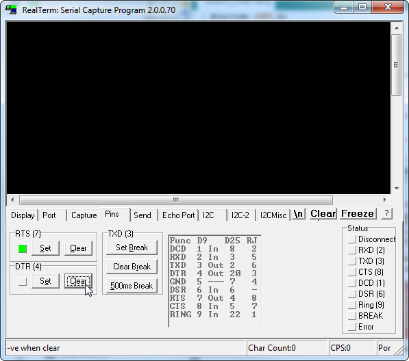
Unfortunately, this Windows-only solution is the only terminal program we've found so far with such control. Your best bet may be to try to avoid serial debugging whenever possible -- that's what LED's are for, right? (Tongue only kind-of in cheek.)
More ESP8266 Thing Examples
Need a little project inspiration for using the ESP8266 in web client mode with a different data-streaming service and/or IoT platform? Check out this tutorial to log data with ThingSpeak. The tutorial uses the ESP8266 Thing Development board but it will work with the ESP8266 Thing as well.
Internet of Things Experiment Guide
Resources and Going Further
Now that you've successfully got your ESP8266 Thing up and running, it's time to incorporate it into your own project! For more information, check out the resources below:
- Schematic (PDF)
- Eagle Files (ZIP)
- Graphical Datasheet
- GitHub Repo (Design Files) - The ESP8266 Thing is open source hardware! If you need, or just want to look at, the PCB design files, you can find them in our hardware repo.
- SFE Product Showcase
An astoundingly awesome community has grown around the ESP8266. We owe them big time for the amazing Arduino addon they've cooperatively built. For all of your ESP8266 needs, we recommend checking out the esp8266.com Community Forum. In addition to that, here are a few ESP8266-related resources we've found incredibly helpful:
- ESP8266 GitHub User Repos -- Tons of incredible tools can be found here. From Crosstool (to compile your own Xtensa GCC, G++, etc.) to the ESP8266 Arduino GitHub Repo
- ESP8266 Community Wiki -- Related to the community forum, there's a good amount of information available in this wiki.
- NodeMCU Firmware and the NodeMCU Flasher -- NodeMCU is a popular firmware for the ESP8266. It implements a LUA-based interpreter on the ESP8266 MCU.
- Espressif Board Forums -- Espressif, the manufacturers of the ESP8266, have a forum of their own. You can sometimes find updated software development kit downloads, or other helpful links here.
- Espressif GitHub Repos -- Espressif is also somewhat active on GitHub. They host a couple versions of the SDK here.
Need a little project inspiration, now that you've got your ESP8266 Thing up-and-running? Maybe some of these related SparkFun tutorials will help spur some ideas. With its deep sleep ability, the Thing is a great foundation for a WiFi-based weather station, or a friendly, huggable, interactive plushy. You can also connect it to an IoT platform or Raspberry Pi.
Are You Okay? Widget
Internet of Things Experiment Guide
Using Flask to Send Data to a Raspberry Pi
Or check out some of these blog posts for ideas: