Digital Sandbox Experiment Guide
 jimblom,
  bri_huang
What is the Digital Sandbox?
The Digital Sandbox is a learning platform that engages both the software and hardware worlds. It's powered by a microcontroller that can interact with real-world inputs -- like light or temperature sensors -- while at the same time controlling LEDs, motors, and other outputs.
By interfacing the Sandbox to your PC or Mac via a USB cable, the Sandbox can be programmed using the popular Arduino programming environment. To further simplify the learning experience, we've designed the Sandbox and this guide around using a simple, "blocky", programming addon to Arduino -- Ardublock.
The Anatomy of the Digital Sandbox
The Digital Sandbox includes a variety of on-board inputs and outputs that are commonly encountered in the world of electronics. Here is an overview of what's included on the board:
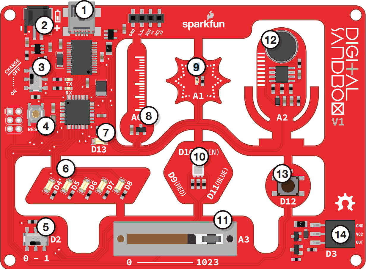
- USB Mini-B Connector -- Used to connect to a computer.
- JST Right-Angle Connector -- Used to supply power to the board.
- Slide Switch for Charging -- Used to charge a lithium polymer battery that is plugged into the two-pin JST connector, while the Digital Sandbox is connected to a computer and the slide switch is in the "ON" position.
- Reset Button -- This is a way to manually reset your Digital Sandbox, which will restart your code from the beginning.
- Slide Switch (Pin 2) -- On or off slide switch.
- LEDs (Pins 4-8) -- Use one or all of the LEDs (light-emitting diodes) to light up your project!
- LED (Pin 13) -- Incorporate this into your sketch to show whether your program is running properly.
- Temperature Sensor (Pin A0) -- Measures ambient temperature.
- Light Sensor (Pin A1) -- Measures the amount of light hitting the sensor.
- RGB LED (Pins 9-11) -- RGB (red/green/blue) LEDs have three different color-emitting diodes that can be combined to create many colors.
- Slide Potentiometer (Pin A3) -- Change the values by sliding it back and forth.
- Microphone (Pin A2) -- Measures how loud something is.
- Push Button (Pin 12) -- A button is a digital input. It can be either “on” or “off.”
- Add-on Header (Pin 3) -- Three-pin header for add-ons. Example add-ons are servos, motors and buzzers.
Digital Sandbox Baseplate Setup
Secure the Digital Sandbox board to the baseplate with the included Phillips-head screws.
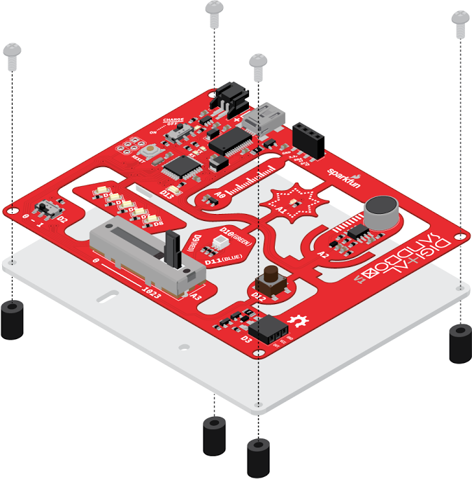
Finger-tighten the screws for easy removal later.