Digital Sandbox Experiment Guide
16: Servo Sweeper (Addon)
DC motors are great for spinning an object at high speed with no regard for where it starts or stops. For many applications, though, it's important to precisely control the position of a motor. Wing flaps in a plane, steering mechanisms in RC cars, and robotic arm platforms are applications that benefit from motorized position control. For those applications we ditch the DC motor and whip out the servo!
Note: This experiment requires the Digital Sandbox Add-On Kit, purchased separately.
Background Information
A servo motor is like a DC motor with an internal controller and built-in sensors that help keep track of its shaft position. A servo motor knows, for example, if it's pointing at 15° or 115°.
Servos all have three wires that need connecting to: supply voltage, ground, and a signal. The voltage and ground connections supply the motor with power, and the control signal - a PWM output (surprise, surprise) - sets the position of the motor. Once the motor reaches the desired position, it stops until it is commanded to move to a new position.
Servo motors vary in their range of motion - the minimum and maximum angles they can point to. Only specialized, continuous rotation servos can rotate a full 360°; most have a stated range of motion between 90° and 180°. The servo we'll be using in this experiment has a 180° range of motion.
Active Parts
Code Components
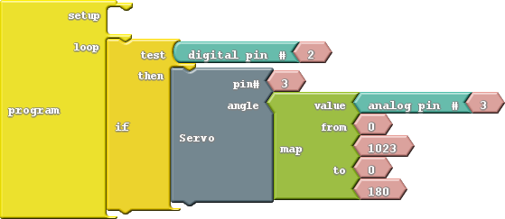
This experiment introduces the Servo block. Here is the layout:
- Servo: This block, found under the Utilities bin, allows you to move a servo to a set position. There are two inputs to supply to the Servo block: pin number and angle. Servos can be connected to any pin, we'll use the multi-purpose pin 3 in this example. The angle should be a number between zero and the maximum range of your servo. In this case we'll constrain the range between zero and 180 using the Map block.
Do This
Construct the program as shown, and upload it to the Sandbox.
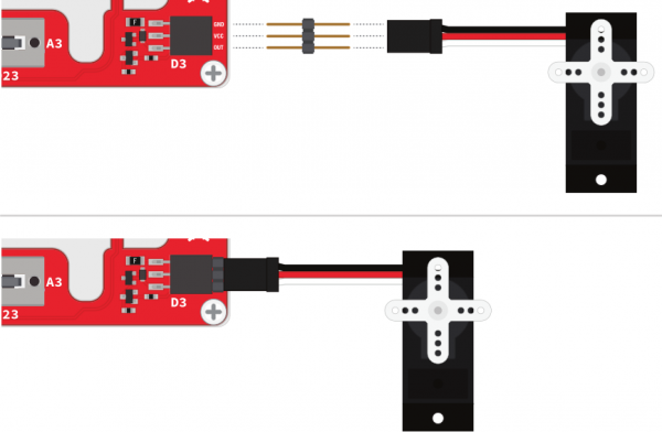
After the code has been uploaded, connect the servo with the three pin male breakaway header to the Sandbox. Make sure the servo’s black wire (GND) is lined up to the GND pin on the Sandbox, as shown here:
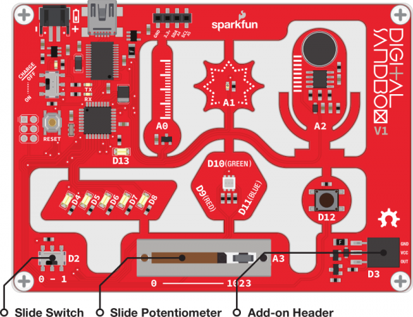
This program allows you to control the position of the servo motor with the sliding potentiometer. Slide all the way to the right to set the servo to 180°, and all the way to the left sets it to 0°.
The servo will only move if the switch (connected to pin 2) is set to ON. If you leave the switch in the ON position, you can see how fast the motor responds to the servo block. If you move the switch to OFF, set the position of the slide pot, and set the switch to ON, you can see the speed and control mechanisms of the motor.
Further Explorations
- What happens if you try to rotate the servo beyond 180° (change the last value in the map function)?
- Think of something to attach to the servo! You could add a clock hand to make a weird, half-circle clock. Or add a papercraft hand, and have your Sandbox give you a high-five!


