Dialog ULP WiFi DA16200 R3 Shield Hookup Guide
 Alex the Giant, Ell C
 Introduction
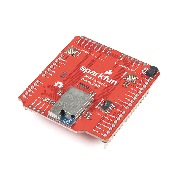
Ultra. Low. Power. Arguably the best three words in the IoT world. SparkFun has teamed up with ARM and Dialog to provide you with the ULP WiFi R3 Shield based around the DA16200 module. The DA16200 is a fully integrated WiFi module with a 40MHz crystal oscillator, 32.768KHz RTC clock, RF Lumped RF filter, 4MB flash memory, and an onboard chip antenna. With the addition of a Qwiic connector, multiple GPIO options, JTAG connectors for deep dive programming, and you've got everything you need to get your R3 layout device ready to set up your next IoT project.
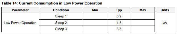
The SparkFun Qwiic WiFi Shield is ideal for door locks, thermostats, sensors, pet trackers, and other home IoT projects, thanks in part to the multiple sleep modes that allow you to take advantage of current draws as low as 0.2uA-3.5uA.
Additionally, the DA16200 module's certified WiFi alliance for IEEE802.11b/g/n, WiFi Direct, and WPS functionalities means that it has been approved for use by multiple countries and using the WiFi Alliance transfer policy, each WiFi Certification can be transferred without being tested again.
Required Materials
To follow along with this tutorial, you will need the following materials. You may not need everything though depending on what you have. Add it to your cart, read through the guide, and adjust the cart as necessary.
Tools
You will need a soldering iron, solder, and general soldering accessories.


Suggested Reading
If you aren’t familiar with the following concepts, we recommend checking out these tutorials before continuing.
Connectivity of the Internet of Things
Arduino Shields v2
Hardware Overview
There's a lot to cover with this board. Let's get started!
DA16200
At the heart of this board is the DA16200 from Dialog - a fully integrated Wi-Fi® module with ultra-low power consumption, 40 MHz crystal oscillator, 32.768 KHz RTC clock, RF Lumped RF filter, 4 M-byte flash memory, and an onboard chip antenna. This chip is chock full of features - for more information, refer to the datasheet.
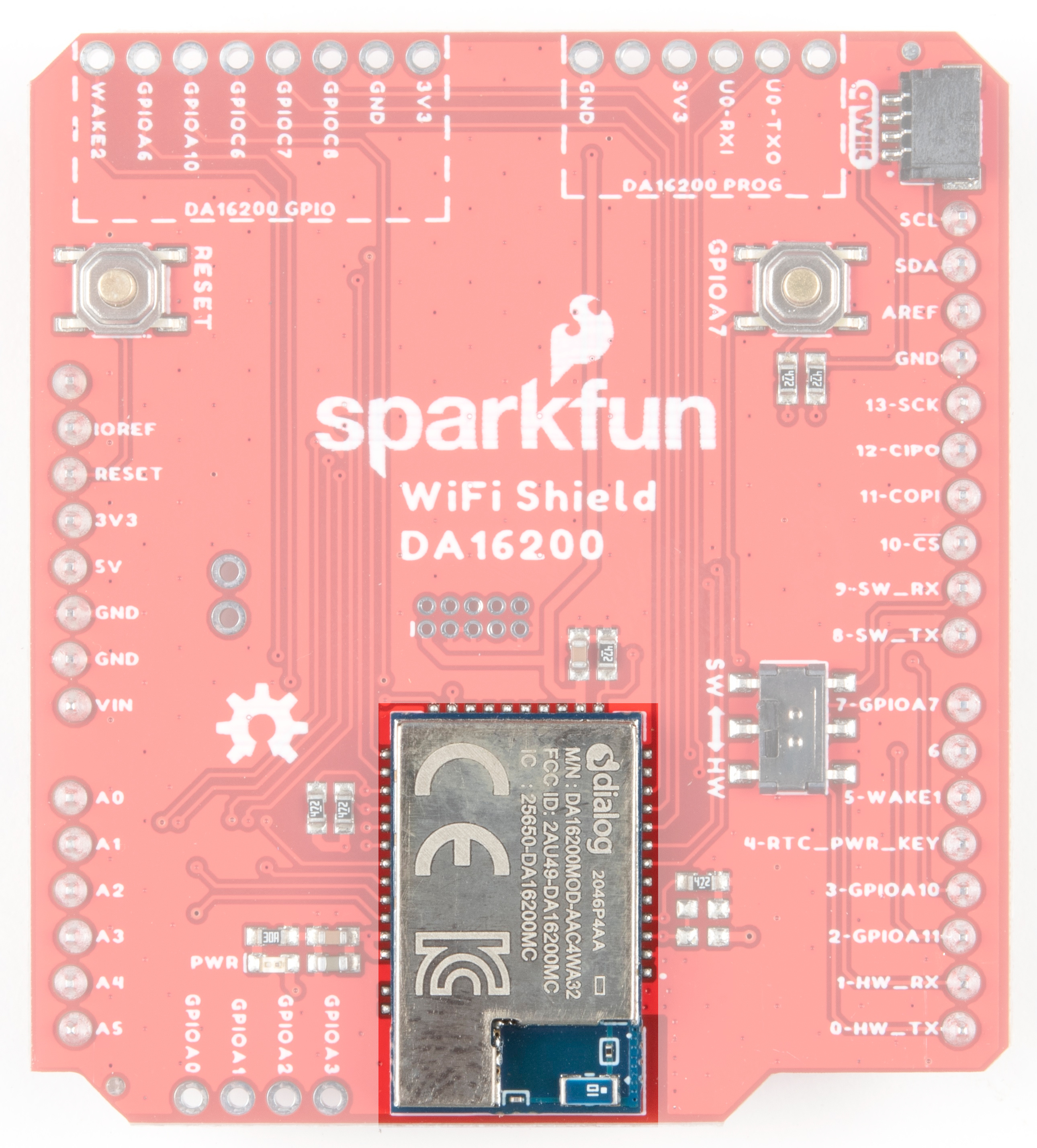
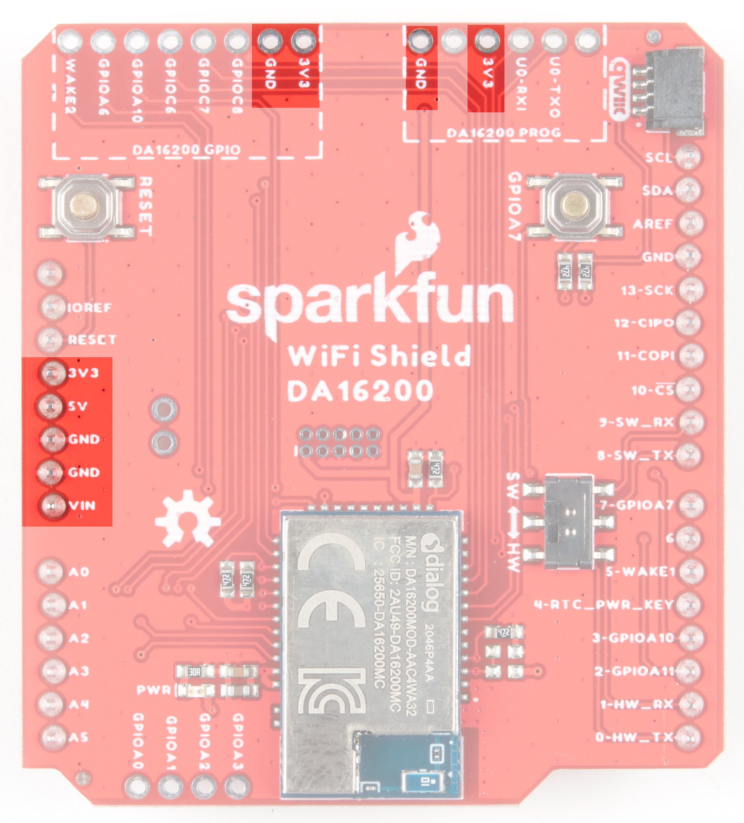
Power
Power is available via a number of pins on the shield.
Wake
Integral to the ultra low power functionality is the wake-up controller. It is designed to wake up the DA16200 from a sleep mode by an external signal that selects either the rising edge or the falling edge on either WAKE1 or WAKE2. The RTC_PWR_KEY is used to enable the RTC block and switch between the various sleep modes. See the datasheet for more information.

Current Draw in Low Power Modes
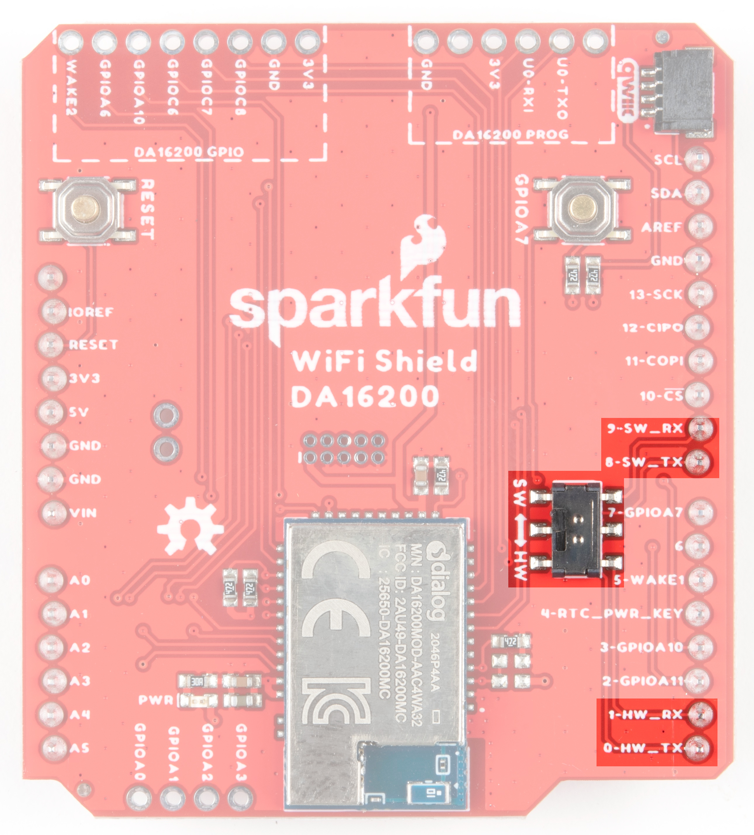
UART
The DA16200 module has two UART interfaces. UART0 is used for updating the firmware to module, and UART1 is used for sending AT commands.
UART0 for the Dialog module sits at the top of the board.
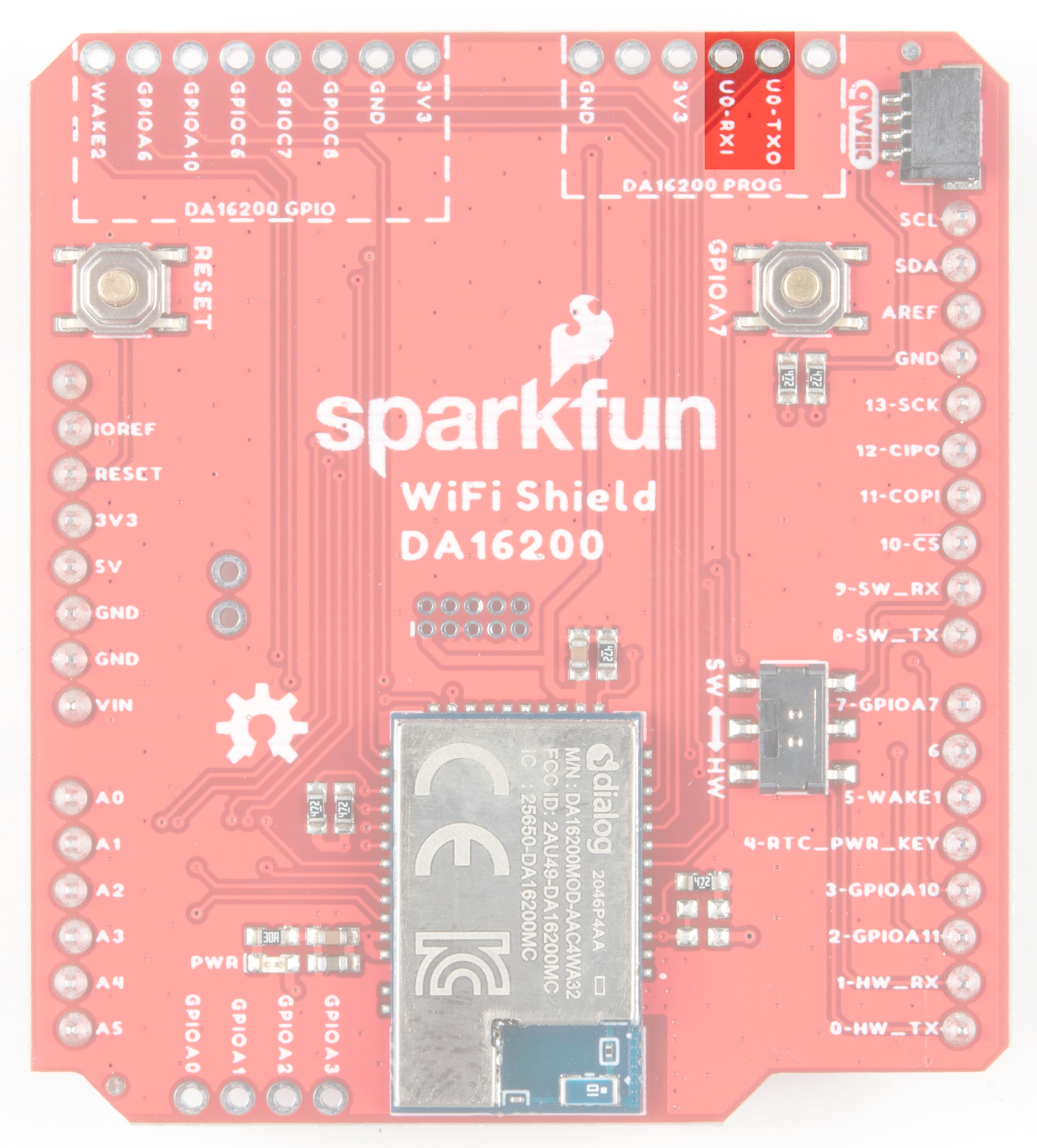
UART1 is used for sending AT commands and is routed through a switch to communicate through either the hardware UART pins D0/D1 for RX/TX, or software UART through D9/D8 for RX/TX.
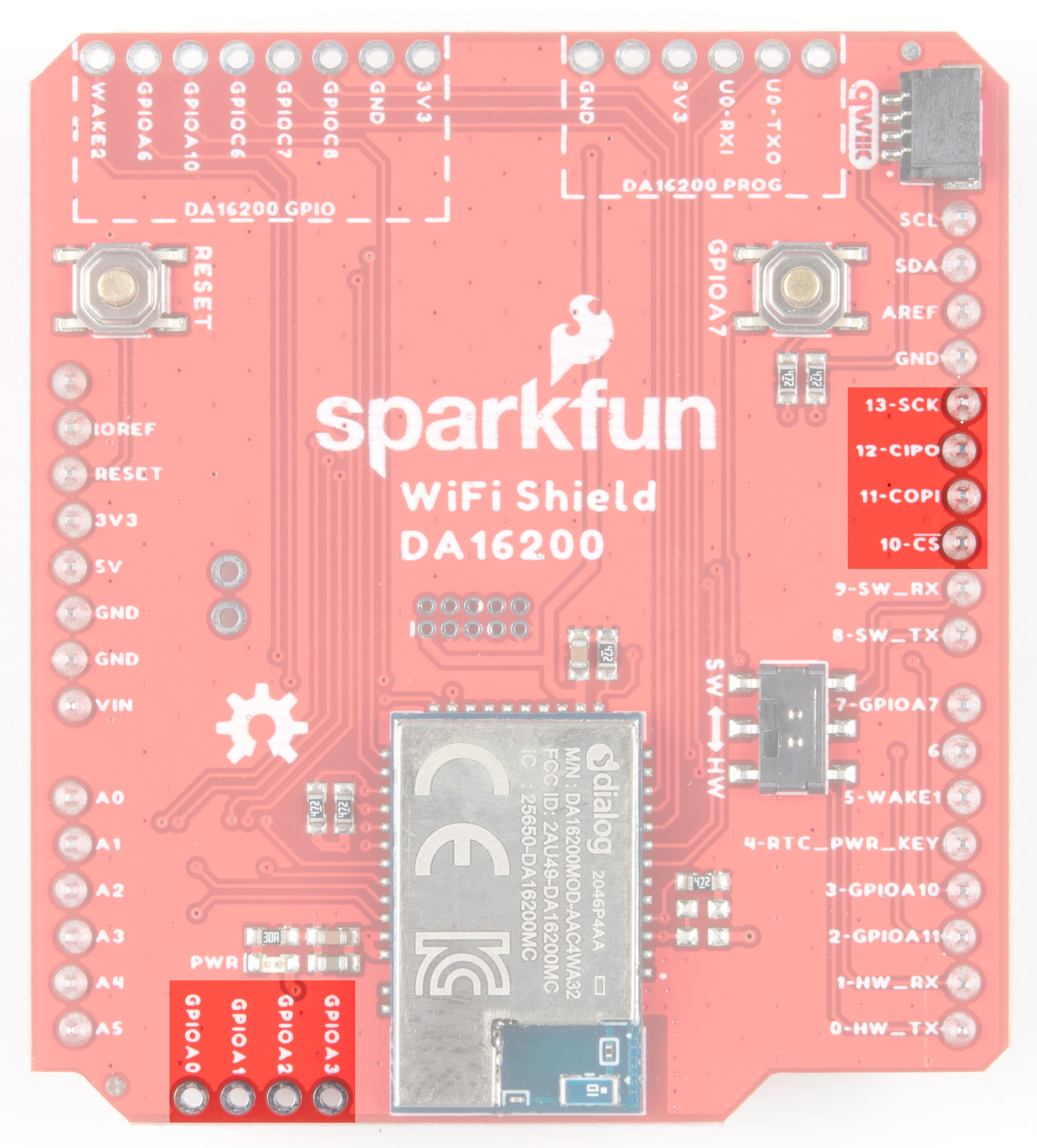
SPI
SPI functionality is found on pins 10-13 on the right side of the board. If you wish to bypass the SPI pins and instead use the ADC on GPIOA0-GPIOA3, there are jumpers on the back of the board to accomplish this. Refer to the Jumpers section below for more information.
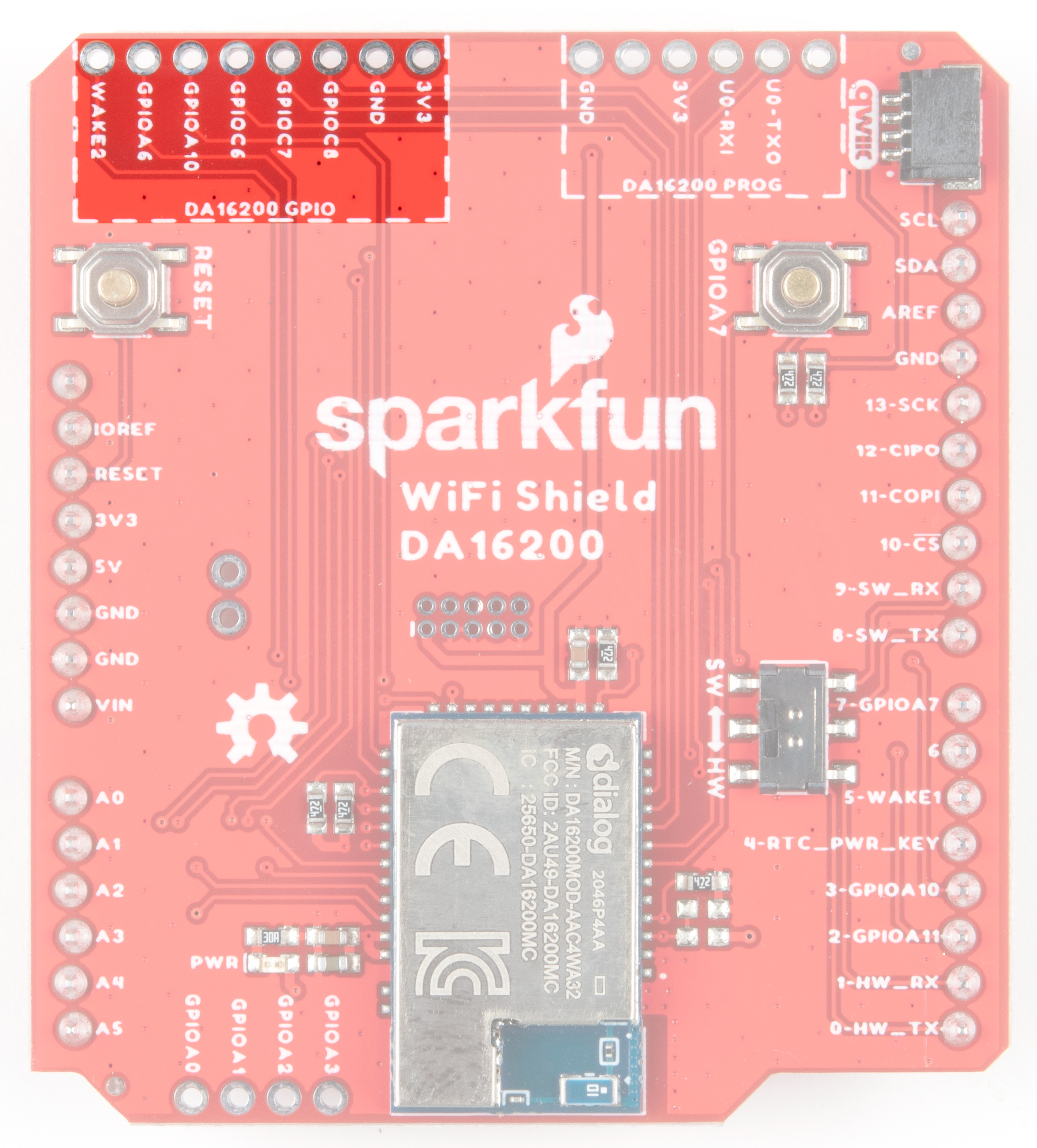
DA16200 GPIO
General purpose IO pins for the Dialog module are available at the top of the board.
Qwiic Connector
A Qwiic connector is provided such that if you have an older RedBoard without a Qwiic connector, you can still add on a Qwiic sensor of your choice. Or you can use both the existing Qwiic connector on your RedBoard as well as the Qwiic connector on your shield. The RedBoard itself acts as the I2C controller. If you need help choosing a Qwiic sensor, check out our Qwiic Ecosystem.

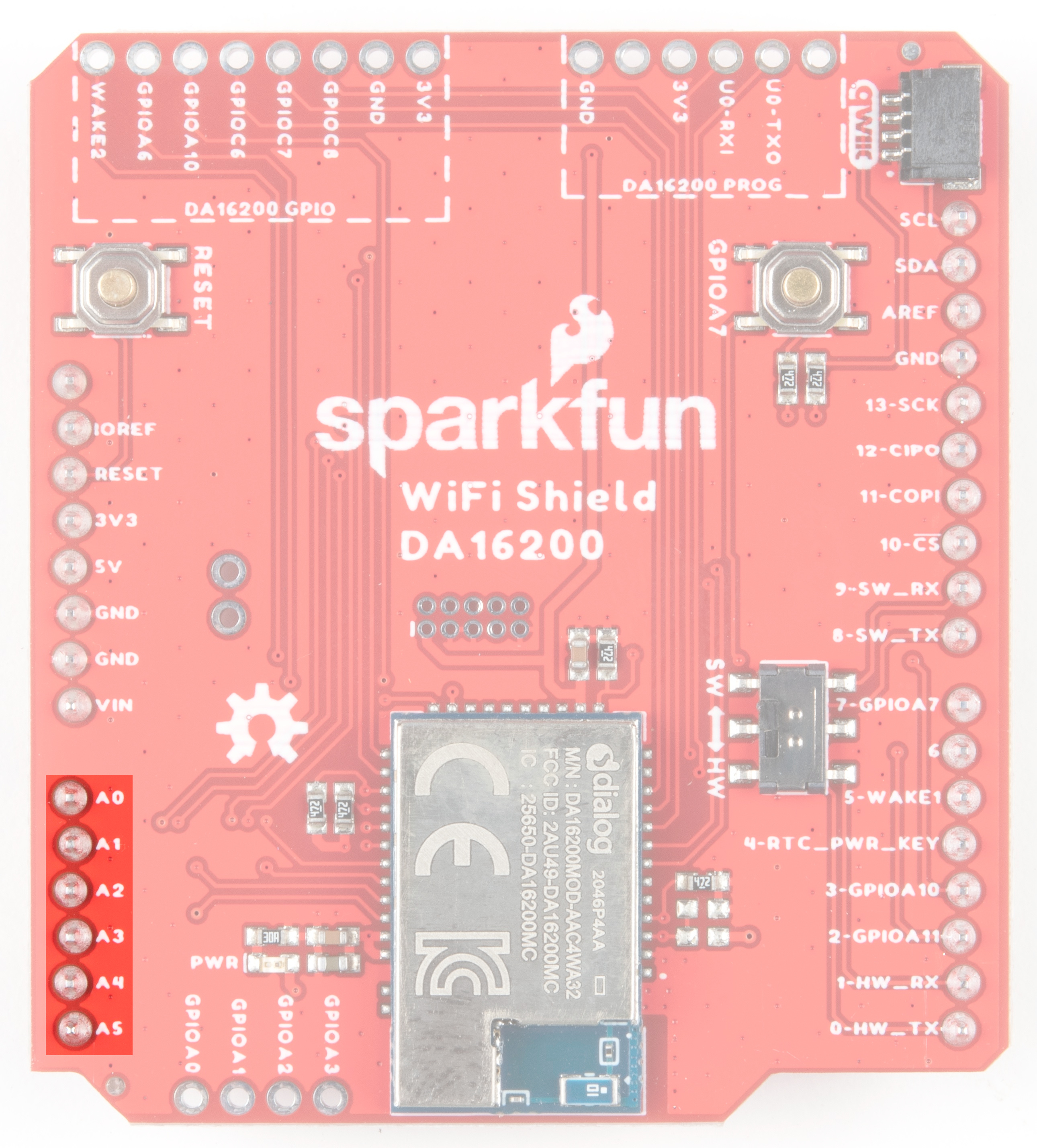
Pins A0-A5
These pins are present on the board, but are not routed to anything on the shield.
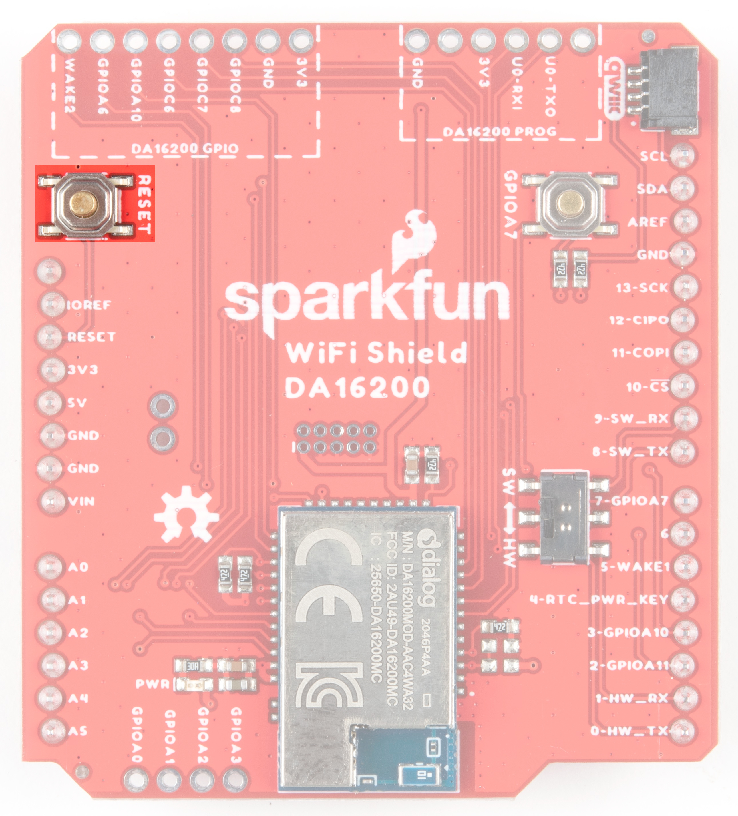
Buttons
A general reset button is located on the upper left side of the board.
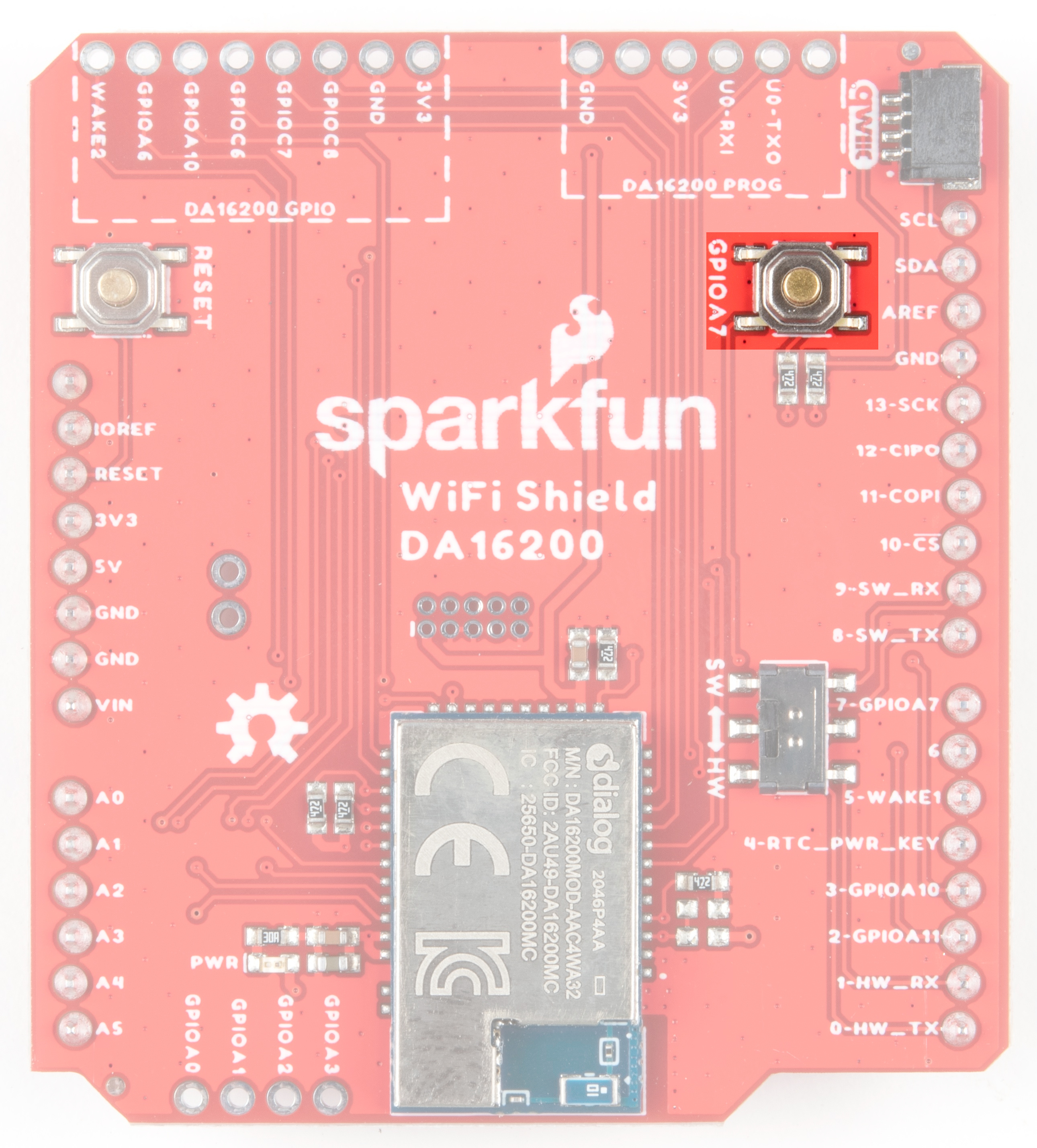
Pressing and holding GPIOA7 will perform a factory reset, which clears configurations that might have been saved to the module.
Jumpers
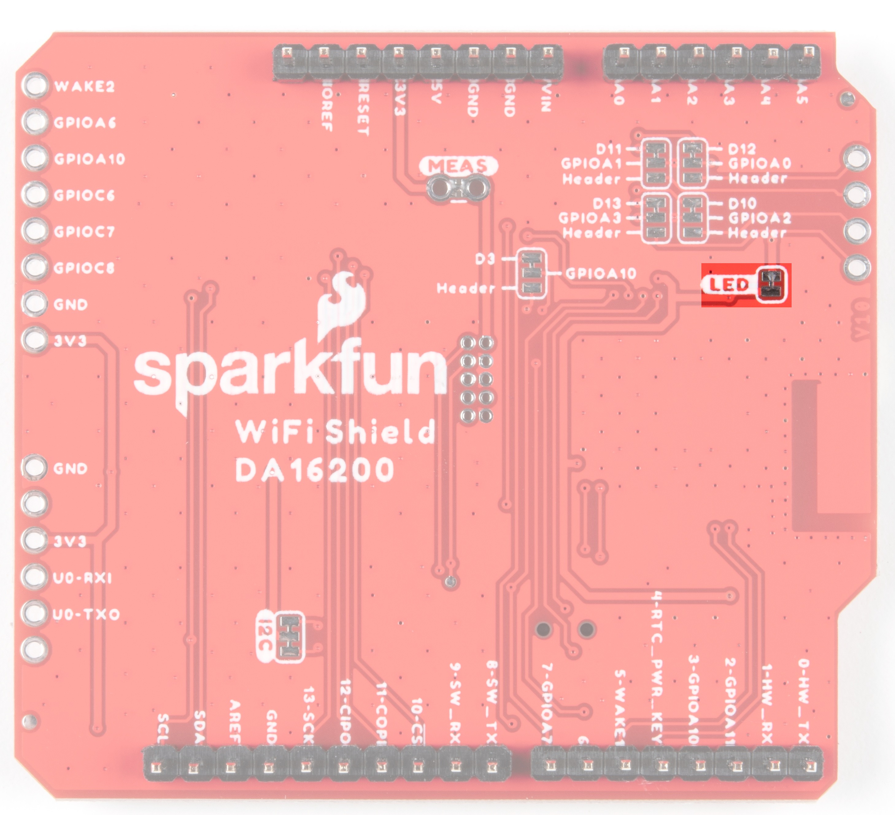
JP1
Cutting this jumper removes power from the LED on the front of the board.
JP2
SPI CIPO is the default functionality for this shield. Cutting this jumper and closing the jumper between GPIOA0 and Header selects for GPIO A0 (Analog to Digital Converter functionality for Dialog Chip).

JP3
SPI COPI is the default functionality for this shield. Cutting this jumper and closing the jumper between GPIOA1 and Header selects for GPIO A1 (Analog to Digital Converter functionality for Dialog Chip).

JP4
SPI CS is the default functionality for this shield. Cutting this jumper and closing the jumper between GPIOA2 and Header selects for GPIO A2 (Analog to Digital Converter functionality for Dialog Chip).

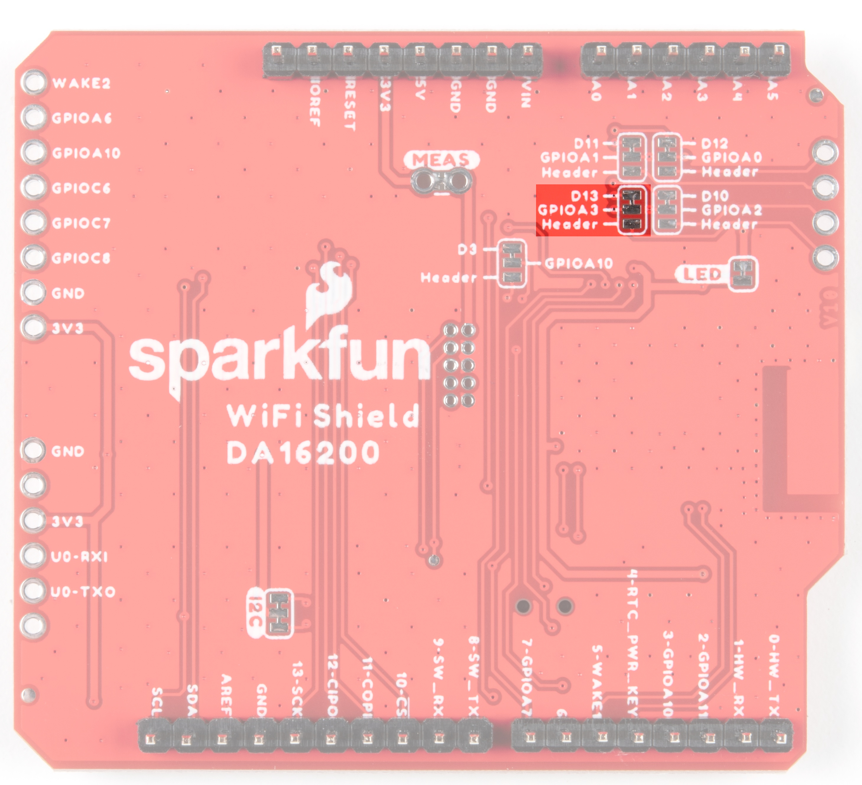
JP5
SPI SCK is the default functionality for this shield. Cutting this jumper and closing the jumper between GPIOA3 and Header selects for GPIO A3 (Analog to Digital Converter functionality for Dialog Chip).
JP6
Selects SPI Interrupt to Arduino (default) or PWM to GPIO header

Current Measurement Jumper
To enable measurements and to isolate the power hungry devices, we've added a NC (normally closed) jumper. By cutting the jumper on the back of the board, the VDD trace to the module is interrupted. Soldering in a male jumper or wires into the accompanying holes will give you the ability to insert a current meter and precisely monitor how much current your application is consuming.

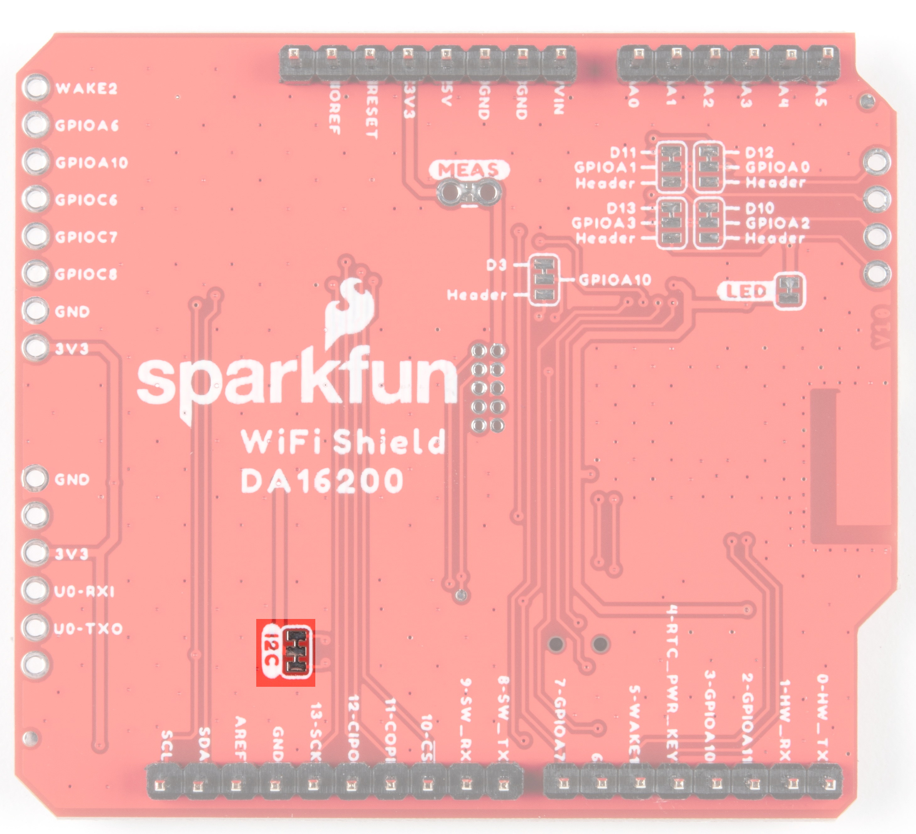
I2C Jumper
Cutting this jumper will disable the pull up resistors on the bus.
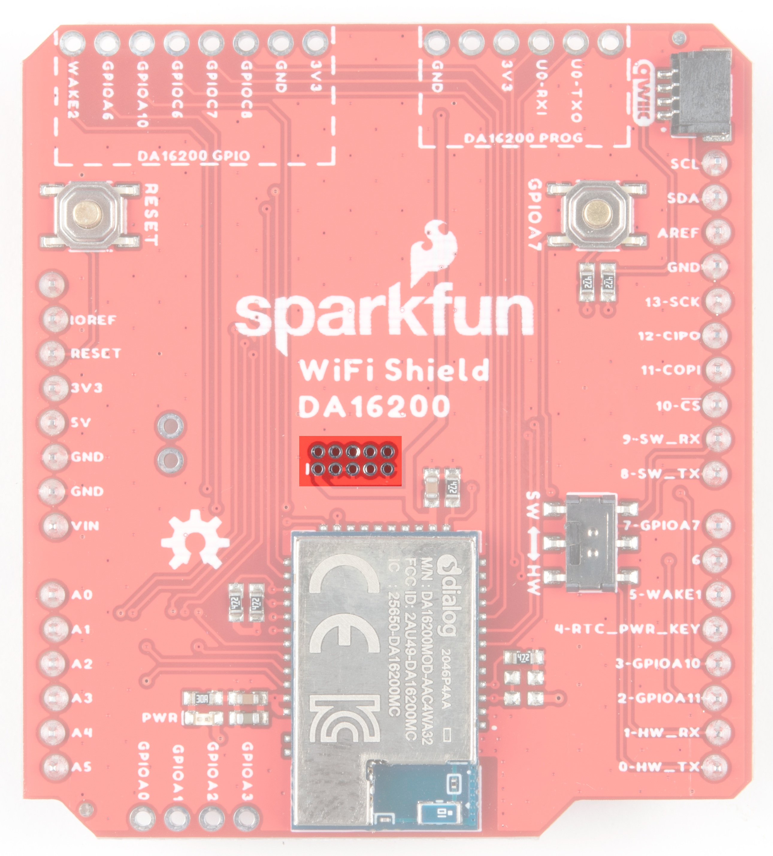
JTAG
An unpopulated JTAG footprint is available for more advanced users who need breakpoint level debugging. We recommend checking out our JTAG section for the compatible male header and a compatible JTAG programmer and debugger.
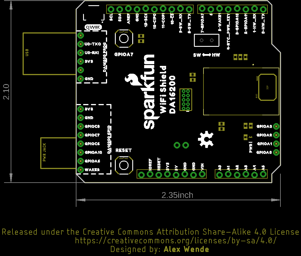
Board Outline
Hardware Hookup
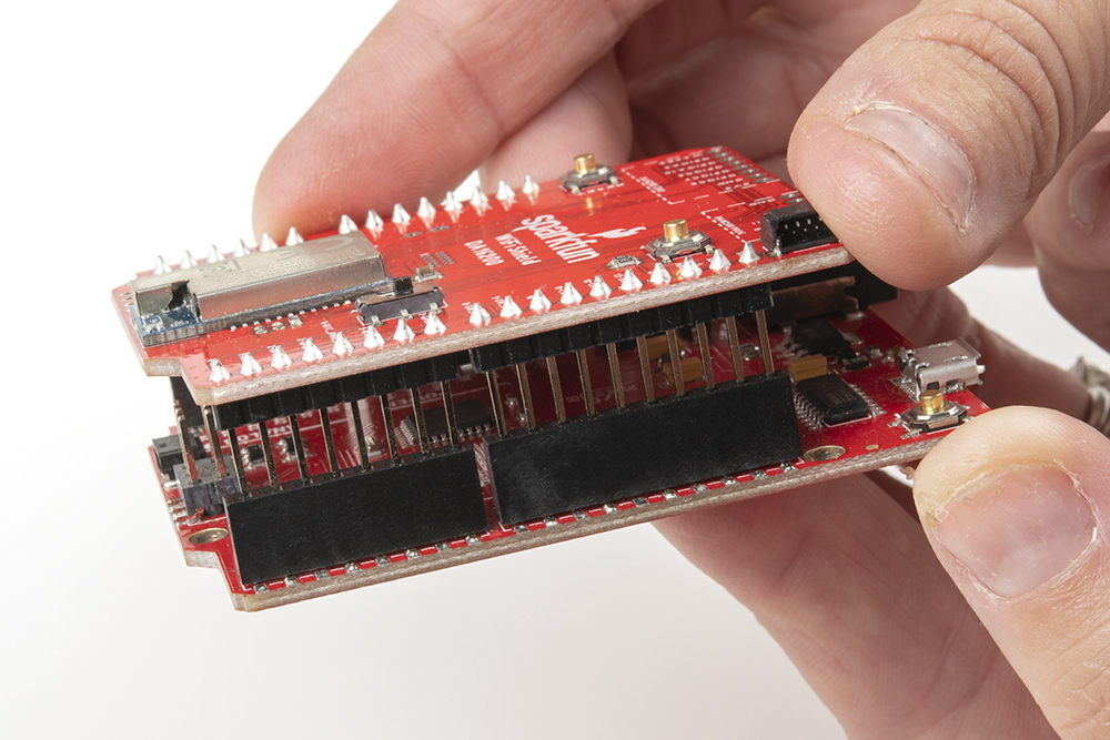
The Dialog ULP Wifi DA16200 Shield comes with headers pre-soldered to the Arduino facing pins. This makes the shield pretty much plug and play when using our standard RedBoard footprint. However, should you wish to use the edge pins for the DA16200 or the ADC, you'll need to solder headers to those plated through holes.
To plug your shield into the RedBoard, line up the pin labels and gently push the connectors together. Voila!
Example 1: Baud Rate Shenanigans
If this is your first time using Arduino IDE, library, or board add-on, please review the following tutorials.
Now that we have the nitty-gritty out of the way, let's look at a few use cases for our Shield.
In this first example, we're going to show you how to change the baud rate to manage serial communications. For boards that have a second hardware UART available, you'll be able to operate at the default baud rate. For other boards, like those based around the ATmega328 (like the RedBoard Qwiic), softwareSerial has a difficult time reading data sent at the higher baud, and it's recommended to lower the baud rate down to 9600 using the ATB command, and then changing the softwareSerial baud down from 115200 to 9600. This example will show you how to do that.
To begin with, copy and paste the code below into a fresh Arduino sketch.
language:c
#include<SoftwareSerial.h>

#define RX1 8
#define TX1 9
#define RTC_PWR_KEY 4

#define SOFTWARE_SERIAL_BAUD 115200
//#define SOFTWARE_SERIAL_BAUD 9600

SoftwareSerial WiFiSerial(RX1,TX1); //Configure SoftwareSerial

void setup() {
  Serial.begin(9600);
  WiFiSerial.begin(SOFTWARE_SERIAL_BAUD); //Set SoftwareSerial baud


  //Enable DA16200 Module RTC power block
  pinMode(RTC_PWR_KEY,OUTPUT);
  digitalWrite(RTC_PWR_KEY,HIGH);

  Serial.println("DA16200 AT Command example sending/receiving commands\n");


  //Listen for ready message ("+INIT:DONE")
  byte count = 0;
  String msg = "";
  while(count<20)
  {
    while(WiFiSerial.available())
    {
      msg += char(WiFiSerial.read());
    }
    if(msg.length() > 5) break;
    count++;
    delay(100);
  }
  msg = msg.substring(3,msg.length());

  if(msg.length()>5)
  {
    Serial.println("Expecting: \"INIT:DONE,(0 or 1)");
    Serial.println("Received: " + msg);
  }
  else
  {
    Serial.println("Failed to receive initialization message\n");

    Serial.println("Make sure the baud rate for WiFiSerial matches the baud rate\n" \
                   "saved to the DA16200. You can also perform a factory reset by\n" \
                   "pressing and holding the GPIOA7 button for ~5s, which will\n" \
                   "reset the baud rate back to 115200");
  }

  Serial.println("\nTry entering \"?\" or \"help\" to print out the list of AT commands\n" \
                 "\nIf the received text is unreadable, try changing the baud rate to\n" \
                 "9600 with the command \"ATB=9600\" in the terminal. Next, update the\n" \
                 "example code by setting SOFTWARE_SERIAL_BAUD to 9600 baud and trying again.\n");
}

void loop() {
    while(Serial.available())
    {
      WiFiSerial.print(char(Serial.read()));
    }

    while(WiFiSerial.available())
    {
      Serial.print(char(WiFiSerial.read()));
    }
}
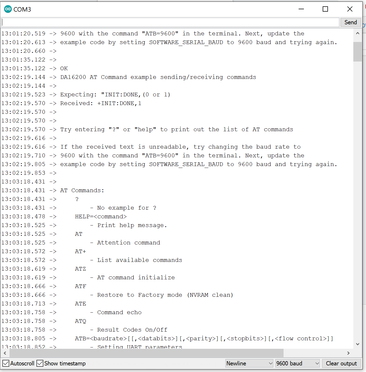
Set your Board and Serial Port, and then upload the sketch to your Arduino. Then open the serial monitor. You'll begin to see output.
If you type "?" or "help" it will print out all of the AT commands. However, at the higher baud rate of 115200 there's a lot of receive errors on a 328 board. To fix this, send the baud rate command for 9600 - "ATB=9600" and you should get an "OK" response. Once that's done you can go back to sketch and comment out the #define SOFTWARE_SERIAL_BAUD 115200, uncomment the line below that defines the software serial baud for 9600, and then re-upload the sketch.
Make sure the baud rate on the serial monitor is set to 9600 and then try typing "?" or "help" again.
Example 2: GPIO and LEDs
In this example, we're going to show you how to use the provided GPIO. Before we get started, let's get our hardware all hooked up.
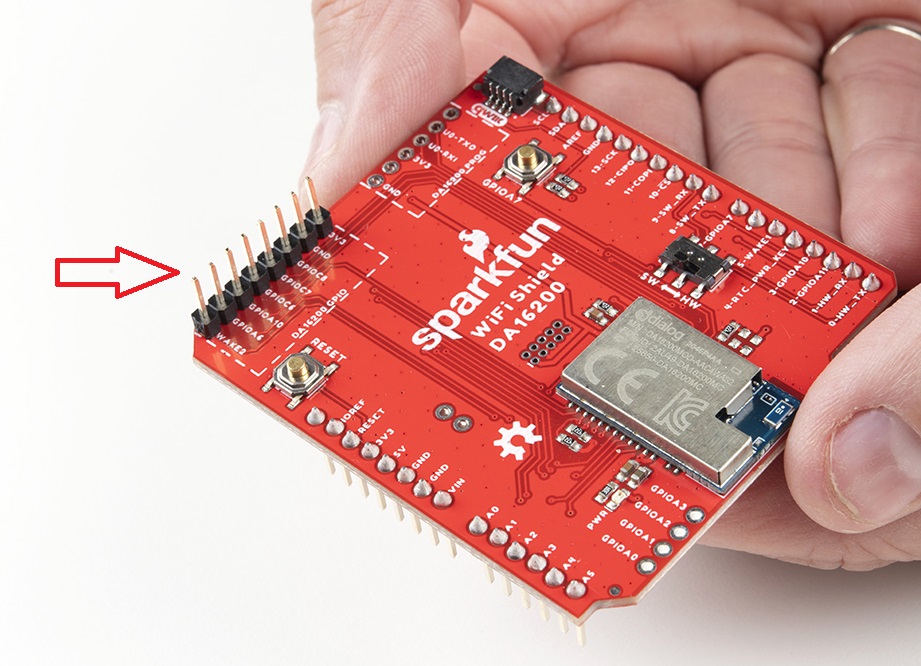
To start with, you'll need to solder headers to the DA16200 GPIO PTH pins.
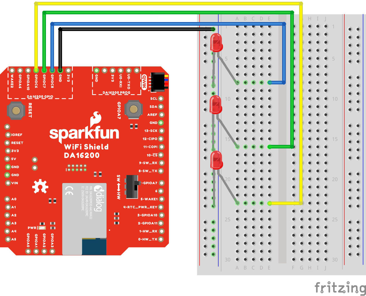
With your shield plugged into a SparkFun RedBoard (with 3.3V logic!!!), connect up your LEDs like so:
- Connect LED1 with current limiting resistor to GPIOC6
- Connect LED2 with current limiting resistor to GPIOC7
- Connect LED3 with current limiting resistor to GPIOC8
Make sure switch is in the "SW" position. Here's a Fritzing image to help you sort out the connections:
Our actual hookup looks like this:

Plug your board into your computer, and copy and paste the code below into a fresh Arduino sketch. Find the lines that define the SOFTWARE_SERIAL_BAUD and uncomment the line that contains the appropriate baud rate.
language:c
/******************************************************************************
  Example_02 Basic Communication

  Configure GPIOC6-8 as output pins, and toggle each LED individually.

  Development environment specifics:
  IDE: Arduino 1.8.13
  Hardware Platform: SparkFun RedBoard Qwiic (3.3V LOGIC!!!!)

  Hardware Connections:
  - Connect the shield to a 3.3V logic Arduino R3 board
  - Connect LED1 with current limiting resistor to GPIOC6
  - Connect LED2 with current limiting resistor to GPIOC7
  - Connect LED3 with current limiting resistor to GPIOC8
  - Make sure switch is in the "SW" position

  ARDUINO --> WiFi Shield --> External
  8       --> RX1
  9       --> TX1
  4       --> RTC_PWR_KEY
  -       --> GPIOC6      --> LED1
  -       --> GPIOC7      --> LED2
  -       --> GPIOC8      --> LED3
  3.3V    --> 3.3V
  GND     --> GND         --> GND

  This program is distributed in the hope that it will be useful,
  but WITHOUT ANY WARRANTY; without even the implied warranty of
  MERCHANTABILITY or FITNESS FOR A PARTICULAR PURPOSE. See the
  GNU General Public License for more details.

  You should have received a copy of the GNU General Public License
  along with this program.  If not, see <http://www.gnu.org/licenses/>.
******************************************************************************/

#include<SoftwareSerial.h>

#define RX1 8
#define TX1 9
#define RTC_PWR_KEY 4

//#define SOFTWARE_SERIAL_BAUD 115200
//#define SOFTWARE_SERIAL_BAUD 9600

SoftwareSerial WiFiSerial(RX1,TX1); //Configure SoftwareSerial

void setup() {
  Serial.begin(9600);
  WiFiSerial.begin(SOFTWARE_SERIAL_BAUD); //Set SoftwareSerial baud

  //Enable DA16200 Module RTC power block
  pinMode(RTC_PWR_KEY,OUTPUT);
  digitalWrite(RTC_PWR_KEY,HIGH);

  Serial.println("DA16200 AT Command Example: Controlling GPIO\n");

  //Listen for ready message ("+INIT:DONE")
  byte count = 0;
  String msg = "";
  while(count<20)
  {
    while(WiFiSerial.available())
    {
      msg += char(WiFiSerial.read());
    }
    if(msg.length() > 5) break;
    count++;
    delay(100);
  }
  msg = msg.substring(3,msg.length());

  if(msg.length()>5)
  {
    Serial.println("Expecting: \"INIT:DONE,(0 or 1)");
    Serial.println("Received: " + msg);
  }
  else
  {
    Serial.println("Failed to receive initialization message.\n" \
                   "Make sure you're using the correct baud rate.\n");
    while(1); //Unable to communcation with module, so don't move forward
  }


  WiFiSerial.println("AT+GPIOSTART=2,1C0,1"); //Configure GPIOC6, GPIOC7, GPIOC8 as outputs
}

void loop() {
  WiFiSerial.println("AT+GPIOWR=2,100,1"); //Set GPIOC8 high
  WiFiSerial.println("AT+GPIOWR=2,0C0,0"); //Set GPIOC6, GPIOC7 low
  delay(200);
  WiFiSerial.println("AT+GPIOWR=2,080,1"); //Set GPIOC7 high
  WiFiSerial.println("AT+GPIOWR=2,140,0"); //Set GPIOC6, GPIOC8 low
  delay(200);
  WiFiSerial.println("AT+GPIOWR=2,040,1"); //Set GPIOC6 high
  WiFiSerial.println("AT+GPIOWR=2,180,0"); //Set GPIOC7, GPIOC8 low
  delay(200);
}
Set your Board and Serial Port, and then upload the sketch to your Arduino. If you've hooked it all up right, you'll see the LEDs flash in order!
Example 3: Connecting to WiFi
Let's check out the WiFi with a simple example to grab the time.
Copy and paste the code below into a fresh Arduino sketch. Find the lines that define the SOFTWARE_SERIAL_BAUD and uncomment the line that contains the appropriate baud rate.
language:c
/******************************************************************************
  Example_03 WiFi Communcation

  Connect WiFi using the provided network credentials
  Talk to NTP server to set the current date/time
  Update the time to the correct time zone
  Print the current time approx. once every second

  Development environment specifics:
  IDE: Arduino 1.8.13
  Hardware Platform: SparkFun RedBoard Qwiic (3.3V LOGIC!!!!)

  Hardware Connections:
  Connect the shield to a 3.3V logic Arduino R3 board
  Make sure switch is in the "SW" position

  ARDUINO --> WiFi Shield
  8       --> RX1
  9       --> TX1
  4       --> RTC_PWR_KEY
  3.3V    --> 3.3V
  GND     --> GND

  This program is distributed in the hope that it will be useful,
  but WITHOUT ANY WARRANTY; without even the implied warranty of
  MERCHANTABILITY or FITNESS FOR A PARTICULAR PURPOSE. See the
  GNU General Public License for more details.

  You should have received a copy of the GNU General Public License
  along with this program.  If not, see <http://www.gnu.org/licenses/>.
******************************************************************************/
#include<SoftwareSerial.h>

#define RX1 8
#define TX1 9
#define RTC_PWR_KEY 4

//#define SOFTWARE_SERIAL_BAUD 115200
//#define SOFTWARE_SERIAL_BAUD 9600

String wifiSSID = "SSID";
String wifiPass = "PASSWORD";

int timezoneOffset = 0; //The hours offset from UTC (Mountain time is -6 for daylight savings, and -7 for standard)

SoftwareSerial WiFiSerial(RX1,TX1); //Configure SoftwareSerial

void setup() {
  Serial.begin(9600);
  WiFiSerial.begin(SOFTWARE_SERIAL_BAUD); //Set SoftwareSerial baud

  //Enable DA16200 Module RTC power block
  pinMode(RTC_PWR_KEY,OUTPUT);
  digitalWrite(RTC_PWR_KEY,HIGH);

  Serial.println("DA16200 AT Command Example: Connecting to WiFi\n");

  //Listen for ready message ("+INIT:DONE")
  byte count = 0;
  String msg = "";
  while(count<20)
  {
    while(WiFiSerial.available())
    {
      msg += char(WiFiSerial.read());
    }
    if(msg.length() > 5) break;
    count++;
    delay(100);
  }
  msg = msg.substring(3,msg.length()); //Remove NULL,CR,LF characters from response

  if(msg.length()>5)
  {
    Serial.println("Expecting: \"INIT:DONE,(0 or 1)");
    Serial.println("Received: " + msg);
  }
  else
  {
    Serial.println("Failed to receive initialization message.\n" \
                   "Make sure you're using the correct baud rate.\n");
    while(1);
  }

  //Configure module for STA mode
  Serial.println("Sending:AT+WFMODE=0");
  WiFiSerial.println("AT+WFMODE=0");

  //Wait for "OK" response
  while(1)
  {
    msg = "";
    while(WiFiSerial.available())
    {
      msg += char(WiFiSerial.read());
      delay(1);
    }
    Serial.print(msg);
    if(msg.length() > 1) break;
  }

  //Apply a software reset to finish changing the mode
  Serial.println("Sending:AT+RESTART");
  WiFiSerial.println("AT+RESTART");

  //Wait for "OK" response
  while(1)
  {
    msg = "";
    while(WiFiSerial.available())
    {
      msg += char(WiFiSerial.read());
      delay(1);
    }
    Serial.print(msg);
    if(msg.length() > 1) break;
  }

  //Listen for ready message ("+INIT:DONE") after the reset is finished
  count = 0;
  msg = "";
  while(count<20)
  {
    while(WiFiSerial.available())
    {
      msg += char(WiFiSerial.read());
    }
    if(msg.length() > 5) break;
    count++;
    delay(100);
  }

  Serial.println(count);
  Serial.println(msg);
  msg = msg.substring(3,msg.length()); //Remove NULL,CR,LF characters from response

  if(msg.length()>5)
  {
    Serial.println("Expecting: \"INIT:DONE,(0 or 1)");
    Serial.println("Received: " + msg);
  }
  else
  {
    Serial.println("Failed to receive initialization message.\n" \
                   "Continuing anyway...\n");
  }

  //Connect to WiFi using the provided credentials
  Serial.println("Sending:AT+WFJAPA=" + wifiSSID + "," + wifiPass);
  WiFiSerial.println("AT+WFJAPA=" + wifiSSID + "," + wifiPass);

  Serial.println("Waiting for connection response...");
  while(1)
  {
    msg = "";
    while(WiFiSerial.available())
    {
      msg += char(WiFiSerial.read());
      delay(1);
    }

    if(msg.length() > 10)
    {
      Serial.print("Response:");
      Serial.println(msg);
      break;
    }
  }

  msg = msg.substring(3,msg.length()); //Remove NULL,CR,LF characters from response

  //If connection to AP is successful, response will be WFJAP:1,SSID,IP_ADDRESS, or WJAP:0 if failed
  if(msg.startsWith("WFJAP:1"))
  {
      //Talk to NTP server to get the current time, along with how often to get time sync
      Serial.println("Sending:AT+NWSNTP=1,pool.ntp.org,86400");
      WiFiSerial.println("AT+NWSNTP=1,pool.ntp.org,86400");

      //Wait for "OK" response
      while(1)
      {
        String msg = "";
        while(WiFiSerial.available())
        {
          msg += char(WiFiSerial.read());
          delay(1);
        }
        Serial.print(msg);
        if(msg.length() > 1) break;
      }

      //Provides the correct UTC offset for the current time
      Serial.println("Sending:AT+TZONE="+String(timezoneOffset*3600));
      WiFiSerial.println("AT+TZONE="+String(timezoneOffset*3600));

      //Wait for "OK" response
      while(1)
      {
        String msg = "";
        while(WiFiSerial.available())
        {
          msg += char(WiFiSerial.read());
          delay(1);
        }
        Serial.print(msg);
        if(msg.length() > 1) break;
      }
  }
  else
  {
    Serial.println("Connection unsucessful :(\n\n" \
                   "Make sure the WiFi credentials are correct, and the module is in the station mode");
    while(1);
  }
}

void loop() {
  //Get the current time
  Serial.println("Sending:AT+TIME");
  WiFiSerial.println("AT+TIME");

  while(WiFiSerial.available())
  {
    Serial.print(char(WiFiSerial.read()));
    delay(1);
  }

  delay(1000);
}
Set your Board and Serial Port, and then upload the sketch to your Arduino. Then open the serial monitor. Make sure your baud rate is set to 9600. You'll begin to see output.
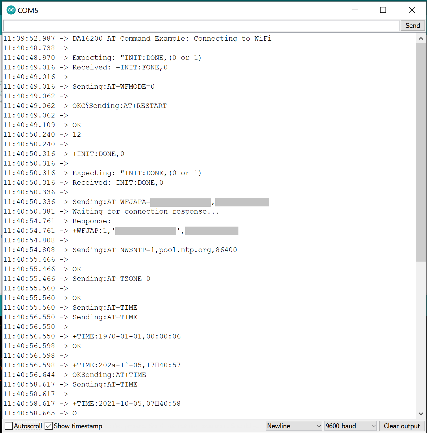
Troubleshooting
Firmware
If, for any reason, you wish to update the firmware, you can refer to the DA16200 AT Command User Manual for more information on downloading the correct firmware via the AT Command.
If your product is not working as you expected or you need technical assistance or information, head on over to the SparkFun Technical Assistance page for some initial troubleshooting.
If you don't find what you need there, the SparkFun Forums are a great place to find and ask for help. If this is your first visit, you'll need to create a Forum Account to search product forums and post questions.
Resources and Going Further
For more information on the WiFi Shield or the DA16200, check out the resources below:
Need some inspiration for your next project? Check out some of these related tutorials: