Designing PCBs: Advanced SMD
How to Create SMD Based PCBs
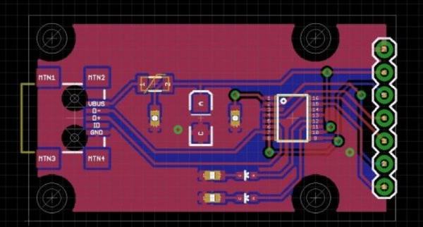
This tutorial will take you through a more advanced SMD layout. It’s a marathon so get yourself a glass of wine and a mouse with a scroll wheel and then dive in.
We’re going to assume you’ve already read our other tutorials on through-hole PCB layout so you should already have Eagle and the various support files installed. We use keyboard shortcuts liberally so you better have them installed as well.
Let’s create a tool that everyone should have in their toolbox: a USB to serial converter board. The FT230X is a pretty neat USB to serial converter that should do the job nicely for us.
We’re going to assume you’re using our library that contains the FT230X. If you want to learn how to create SMD footprints for Eagle from scratch, please see this tutorial.
Suggested Reading
These are the tutorials and concepts you may want to know before starting this tutorial:
- How to Read a Schematic
- PCB Basics
- How to install and setup Eagle PCB software
- How to layout PTH PCBs: Schematic
- How to layout PTH PCBs: Board Layout
- Creating SMD Footprints
