Designing PCBs: Advanced SMD
 Nate
Nate 
Creating the Schematic
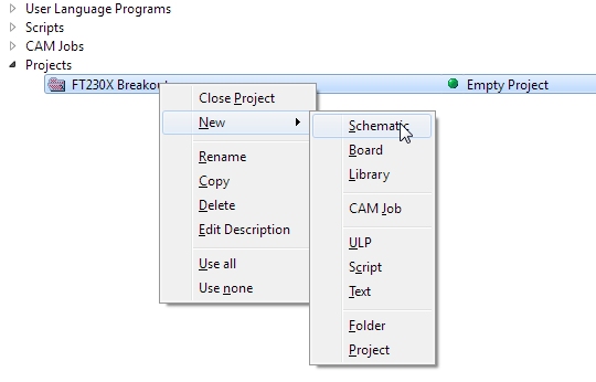
To start, create a new project in Eagle. Right click on the Projects folder and select ‘New Project’. Call the project ‘FT230X Breakout’. Right click on the folder and select New Schematic.
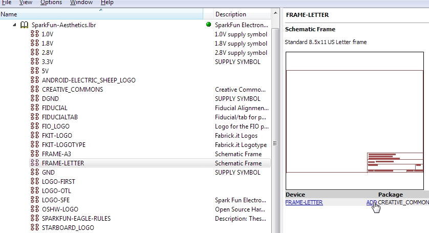
Let’s start by adding a frame to our schematic. From the Eagle main window, navigate to the Libraries folder. Click on the small arrow beside the word 'Libraries' to expand it. Then expand the SparkFun-Aesthetics library (since the frame is just for aesthetics). Navigate to the FRAME-LETTER component and click Add.
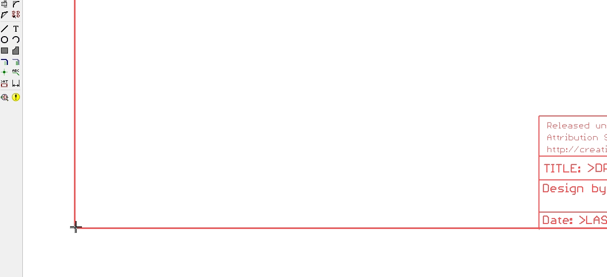
Drop the corner of the frame on the corner of the schematic layout window. Hit escape twice to return to the main schematic window.
Use the scroll wheel to zoom in/out. Press and hold the scroll wheel to drag the schematic window around.
Now let’s add the various bits we’ll need for this example:
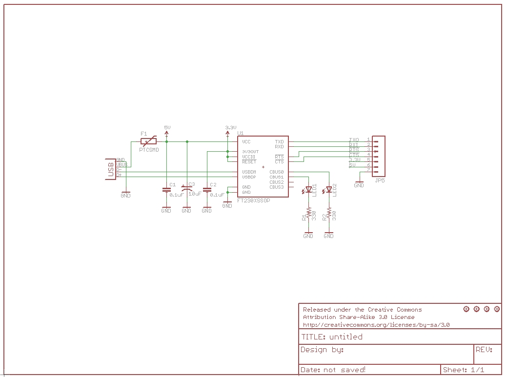
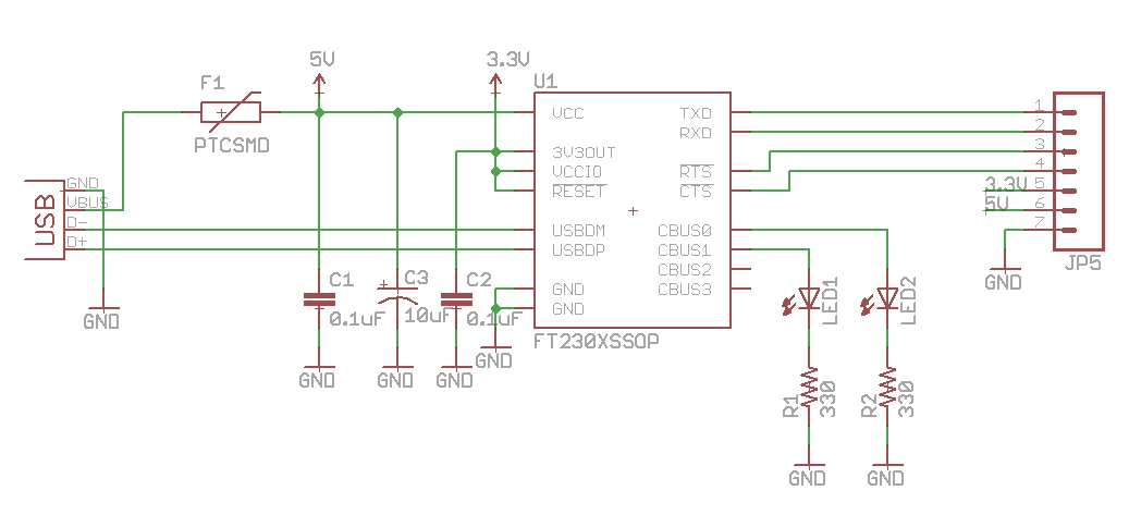
- FT230X component from the DigitalICs library. The best way to get to find the component is to click on any component then press ‘f’ to take you to the components that start with ‘f’. Add this to your schematic. Click once to drop the item. Hit escape twice to return to Eagle main window.
- M07 from the Connectors library. You will want the 'M07' device. This is the most common, 7 pin 0.1” header footprint.
- USB from the Connectors library. You will want the ‘USBSMD’ device (it has the ‘USB-miniB’ package type).
- 5V, 3.3V, and GND from the Aesthetics library.
- Two LEDs from the LED library. You will want LED0603. This is the small 0603 sized surface mount LED.
- Two CAPs from Passives library. Get the CAP0603-CAP package.
- CAP_POL from Passives library. Get the CAP_POL1206-KIT package.
- Two Resistors from the Passives library. You will want RESISTOR0603-RES.
- PTC from the PowerIC library. Get the PTCSMD package.
- Four Stand-offs from Electromechanical. Get the STAND-OFF package.
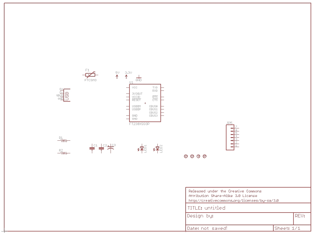
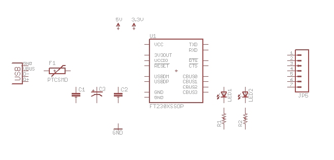
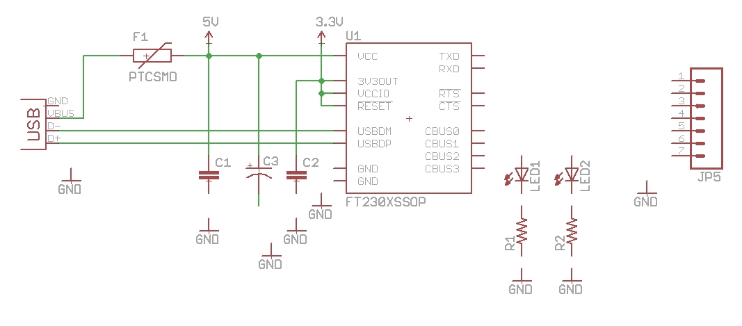
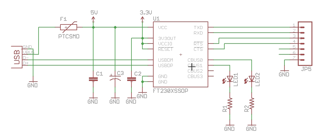
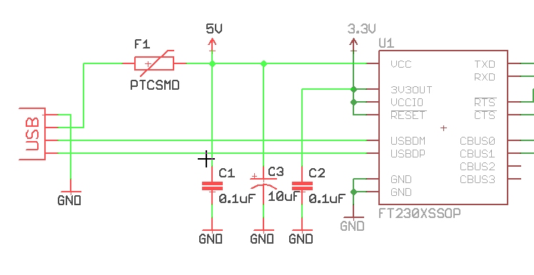
We’ve got all the parts here. Now hit F7 to go into ‘move’ mode. Click on an item and move it around. We’re aiming for the example found in the datasheet. Arrange your components kind of like this:
While you got a component selected and moving, rotate it by right-clicking. Left clicking will set the component down.
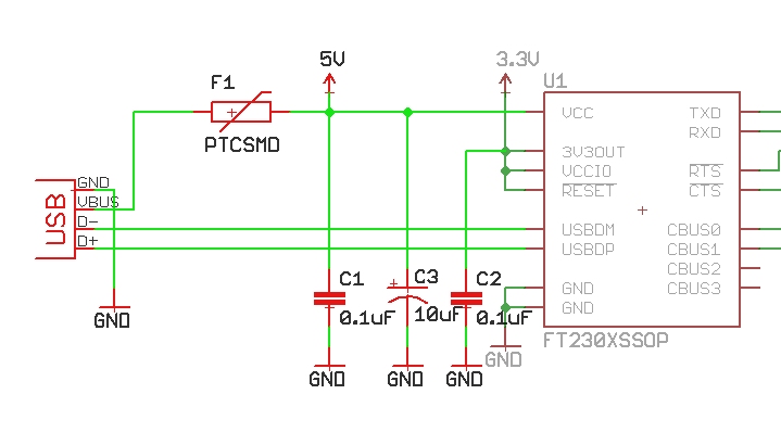
Now press F9 to begin wiring the components together. Click on the end of the D- pin on the USB connector and run it over to the USBDM pin on the FT230X. Click again on the pin and the wire should stop routing indicating that it has been successfully connected.
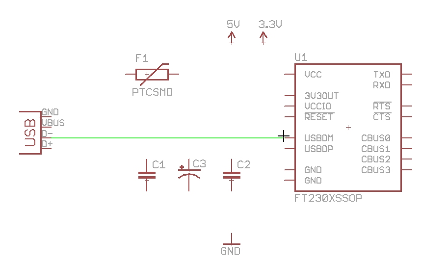
Continue to wire as shown.
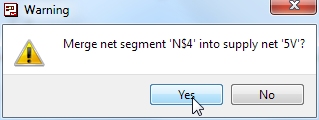
You may get a window that says ‘Merge net segment ‘N$4’ into supply net ‘5V’? or some such warning. The answer is yes you do.
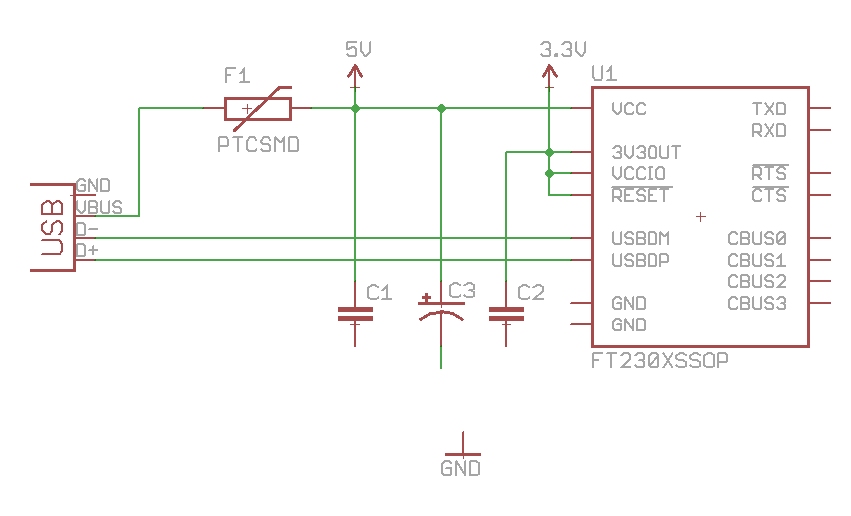
We will need more GND connections. Press F8 to go into copy mode. Click on the GND symbol and create 8 or so copies.
A trick I use a lot is this: Hit F7 to move the GND symbol. Move it directly onto the end of the capacitor and click to drop it.
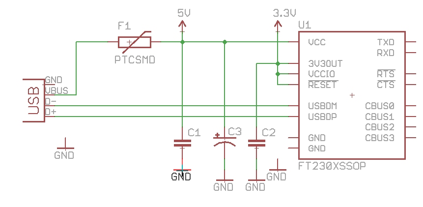
Now click the same ground symbol and move it down. Eagle will automatically have a wire attached. This saves you from having to do a few wire connections by hand.
Wire up more stuff. Note the two stubs of wire on pins 5 and 6 on the 7 pin connector. Those are unnamed, unconnected nets.
Press Alt+F9 to go into ‘Label’ mode. Then left-click on one stub. Eagle will highlight the wiring - this is its way of asking if that is the wire you want to be messing with. Left click again to confirm - Eagle will then show a label for the stub. Click again to anchor the label to the stub. Repeat for the 2nd stub.
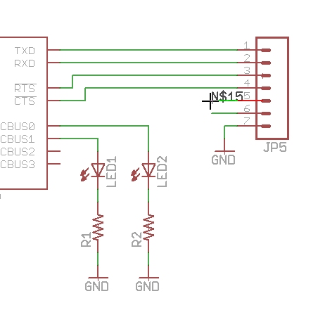
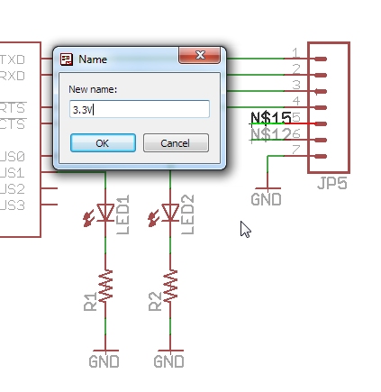
Now press F4 to go into ‘Name’ mode. Click on the first stub. Are you sure you want to connect them? Yes you are. Repeat but name the second net 5V.
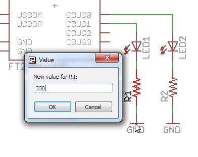
Press F5 to go into ‘Value’ mode. Then click on R1 and set the value to 330. Set the values for the following:
- R2 = 330
- C1 = 0.1uF
- C2 = 0.1uF
- C3 = 10uF
Hey! It’s about time you saved your work! Hit Ctrl+s or the disk icon. Save your work as ‘FT230X-Breakout-v10’. This is the first version so it’s v1.0. If there are changes to be made, save the file as -v11, -v12, etc.
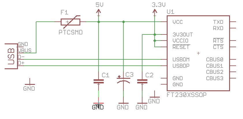
Have a look. The values are sort of running over the wires. Let’s press Alt+F7 to go into ‘Group’ mode.
Move the cursor to the upper left corner. Click and hold the button down, then drag to the lower right corner. Note that we are selecting just past C2.
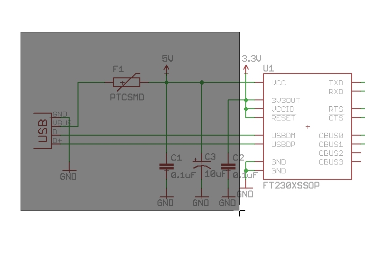
Release the mouse button. You should see a bunch of wires and components selected. Now we've got a group, but we haven't told Eagle what we are doing with this group. Press F7 to go into 'Move' mode. Now let’s move the group! Holding Ctl, click the right mouse button. The group will now be moving with the mouse cursor.
Move it two clicks to the left so that the 0.1uF text doesn't overrun the GND symbol.
Let’s create labels and name the nets near the connector. This will help us in the PCB layout phase. Press Alt+F9 to go into label mode. Click on a wire, Eagle will highlight it. Click again to confirm you want to mess with the highlighted wire. And click a third time to throw a label in that location. Once you have four random labels (such as N$9, N$13, etc), then hit F4 and rename the wires as shown in the picture:
- TXO
- RXI
- !RTS
- !CTS
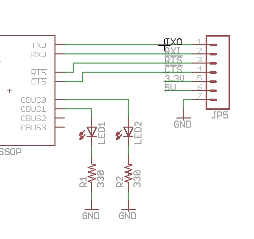
Note the leading '!' will put a line above the net name (neat!).
Looking pretty good! Let's start laying down traces.