Basic LED Animations for Beginners (Arduino)
Introduction
The control of light has been a quest for humankind older than written history. The power of illumination stirs a biological feeling in us all. We've evolved from chemical combustion of energy stored in wood to the greater volatility of gasoline vapor. The physical flame was then replaced by warm, glowing, delicate, metal coils. My favorite method of light is as simple as the humble electron shedding energy through the process of Electroluminescence. Light Emitting Diodes, LEDs, are vastly more energy efficient than past methods and provides near endless possibilities for combating the darkness.
In this tutorial, we will revisit some concepts about using LEDs and make some fun effects using the RedBoard Qwiic to control the individual LEDs.
Required Materials
To follow along with this tutorial, you will need the following materials. You may not need everything though depending on what you have. Add it to your cart, read through the guide, and adjust the cart as necessary.
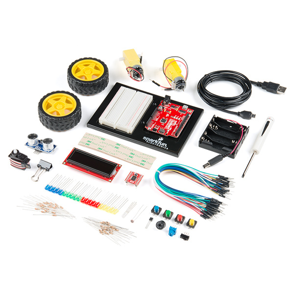
This list is just a trimmed down list from our new SparkFun Inventor's Kit featuring the RedBoard Qwiic. If you'd rather purchase the full set for more electrical goodies, please feel free.
SparkFun Inventor's Kit - v4.1
KIT-15267Revisit Basics
Let's keep in mind a couple of key notes about LEDs:
- Like any other diode, current will only flow in ONE direction.
- High enough voltages will make it flow either way, but only for a split moment, you know, the magic smoke...
- Also, like any other diode, there is a 'minimum' voltage needed to work.
- Lastly, the 'blue-r' the light, the more energy we're using.
If you aren’t familiar with the following concepts, we recommend checking out these tutorials before continuing. Many of these notes listed above were covered in an earlier tutorial explaining basics circuit rules using LEDs. If you want to revisit that tutorial, please feel free to check it out.
Light-Emitting Diodes (LEDs)
If you're new to Arduino, breadboards, or other electronic basics, please take a minute to visit these other tutorials and guides that are full of goodies.
How to Use a Breadboard
What is Electricity?
SparkFun Inventor's Kit Experiment Guide - v4.1
Note: This example assumes you are using the latest version of the Arduino IDE on your desktop. If this is your first time using Arduino, please review our tutorial on installing the Arduino IDE.
If you've never connected an CH340 device to your computer before, you may need to install drivers for the USB-to-serial converter. Check out our section on How to Install CH340 Drivers" for help with the installation.
Forward Voltage
LEDs, like other diodes, require a 'minimum' voltage to work. In circuit analysis, we call this a voltage drop. With diodes, we consider that forward voltage 'using' a chunk of the available voltage. Troubleshooting tip #1:
- Check that the voltage on the anode and cathode meets the minimum forward voltage for operation. I use the term minimum loosely because you can touch an old dying battery to the LED terminals and still see a faint light.
Currently, There's Too Much Current
We've established that there are minimum requirements for LEDs, but there are maximums as well. In most physics books, the analog example for current is water. Well, if you've ever had a pipe burst then you'll know the dangers of too much, too soon. Again, check the datasheet for your LED's and make sure you're not applying too much voltage. If you up the voltage, you up the current. Troubleshooting tip #2:
- If you see a blip of light followed by a dark spot inside the LED, then we've done and busted it. (Also, remember this tip if you have old LEDs that can't seem to light up, maybe someone made an oopsie.)
Resistance Can Be a Force for Good
A big key point for the first two topics is using resistors to limit the current. If your voltage is too high, then using the right resistor can drop that down to a safer level when used in series with the LED. Let's say that the voltage is fine but the diode keeps blowing and you're low on LEDs. While it's not ideal, there are resistors designed to blow at high current: fuse resistor.
Resistors
Simple ON/OFF with GPIO
It’s simple enough to just touch LED pins to a coin-cell, even add a little tape and you have a super simple flashlight. What about control, what about the pizzazz? Just because LEDs only allow current in one direction doesn’t mean you can only go one direction. We’re going to put together some simple components and play around with what microcontrollers can do to for our lighting needs.
Let’s first talk about GPIOs. These are General Purpose Input and Outputs, meant simply for input and output. This means that depending on how we set it up, that pin will receive a voltage signal or put out a voltage signal. On the RedBoard, our “On” (or output) voltage is a super useful 5 Volts. We make the ATMEGA IC do this by writing digitalWrite(PIN_NUMBER, HIGH); in our Arduino code. However, you'll notice that won't really work if you just copy paste that into the loop section. We have to declare what we want that pin to be. So we make a variable to easily reference our pin number: PIN_NUMBER. For the simplicity, we'll use the defualt pin 13 on the RedBoard Qwiic. Then up in setup() function, we need to write pinMode(PIN_NUMBER, OUTPUT);. What this means is that our IC is dedicating that pin to be an output. So when we write that digital high, the IC knows exactly what to do. If you hooked up an multimeter, or oscilloscope, that pin would be at 5V relative the GND (0V) until you declare it LOW with digitalWrite(PIN_NUMBER, LOW);. In a nutshell, that's a blink, off to on and then back to off. We can add time delays for different effects.
language:c
//This example turn a GPIO pin ON and OFF with a delay.

const int PIN_NUMBER = 13; //Replace 'PIN_NUMBER' with a physical pin, we'll use the built-in LED on pin 13 on the RedBoard Qwiic

void setup() {
  pinMode(PIN_NUMBER, OUTPUT);    //set digital pin as output
}

void loop() {

  digitalWrite(PIN_NUMBER, HIGH); //LED connected to pin 13 comes ON
  delay(5000);                    //delay(Milliseconds), so '5000' is 5 seconds
  digitalWrite(PIN_NUMBER, LOW);  //LED connected to pin 13 goes OFF
  delay(5000);                    //delay(Milliseconds), so '5000' is 5 seconds

}
"Ok, What Does this Mean for Me?"
This demonstrates that these "auxillary pins" can be for input, or in our case for output. There are so many options after we make this step. From this point forward, we're going to explore what some fun arrangements, effects, and practical uses for LEDs can be.
I may be hammering home too much about pins on the microcontroller. They warrant their own slew of tutorials, but we're not here for those. I'm pushing them because they will be the web of control for our multiple LEDs.
The big picture is that at some spot in our circuit, there is a point of voltage. If this point of voltage is high enough (and not too high, so we don't blow the LED) then we can illuminate our LED. The output of a GPIO pin is a power source for our needs. One could think of them as fancy switches in a room full of switches and bulbs.
Lights, Camera, ACTION
Blink like Booyah
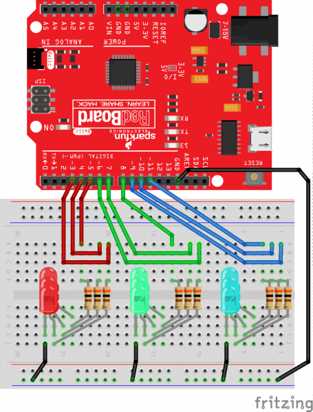
Check out the circuit diagram below to see how everything is connected.
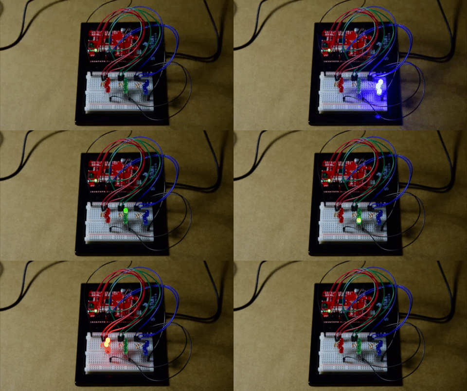
I had a liberty with having some fun with this one. We're turning on each LED set one by one. Once the set is turned on, we'll turn them each off one by one before moving to the next set.
Copy and paste the following code into the Arduino IDE. Hit upload, and see what happens!
language:c
//This example turns on each LED set one by one. Once the set is turned on, we'll turn them each off one by one before moving to the next set.

//Declare pins
const int GREEN_A = 8;
const int GREEN_B = 7;
const int GREEN_C = 6;
const int RED_A = 5;
const int RED_B = 4;
const int RED_C = 3;
const int BLUE_A = 11;
const int BLUE_B = 10;
const int BLUE_C = 9;

const int turn_time = 300;      //Play with this integer!!

void setup() {
  // initialize pins as output
  pinMode(GREEN_A, OUTPUT);
  pinMode(GREEN_B, OUTPUT);
  pinMode(GREEN_C, OUTPUT);
  pinMode(RED_A, OUTPUT);
  pinMode(RED_B, OUTPUT);
  pinMode(RED_C, OUTPUT);
  pinMode(BLUE_A, OUTPUT);
  pinMode(BLUE_B, OUTPUT);
  pinMode(BLUE_C, OUTPUT);
}

void loop() {
  //These sequences just turn on 3 of the same color one by one. Then turn them off
  //one by one.
  digitalWrite(BLUE_A, HIGH);   // turn the LED on (HIGH is the voltage level)
  delay(turn_time);                       // wait for a second
  digitalWrite(BLUE_B, HIGH);   // turn the LED on (HIGH is the voltage level)
  delay(turn_time);                       // wait for a second
  digitalWrite(BLUE_C, HIGH);   // turn the LED on (HIGH is the voltage level)
  delay(turn_time);                       // wait for a second
  digitalWrite(BLUE_A, LOW);    // turn the LED off by making the voltage LOW
  delay(turn_time);                       // wait for a second
  digitalWrite(BLUE_B, LOW);    // turn the LED off by making the voltage LOW
  delay(turn_time);                       // wait for a second
  digitalWrite(BLUE_C, LOW);    // turn the LED off by making the voltage LOW
  delay(turn_time);                       // wait for a second

  digitalWrite(GREEN_A, HIGH);   // turn the LED on (HIGH is the voltage level)
  delay(turn_time);                       // wait for a second
  digitalWrite(GREEN_B, HIGH);   // turn the LED on (HIGH is the voltage level)
  delay(turn_time);                       // wait for a second
  digitalWrite(GREEN_C, HIGH);   // turn the LED on (HIGH is the voltage level)
  delay(turn_time);                       // wait for a second
  digitalWrite(GREEN_A, LOW);   // turn the LED off (HIGH is the voltage level)
  delay(turn_time);                       // wait for a second
  digitalWrite(GREEN_B, LOW);   // turn the LED off (HIGH is the voltage level)
  delay(turn_time);                       // wait for a second
  digitalWrite(GREEN_C, LOW);   // turn the LED off (HIGH is the voltage level)
  delay(turn_time);                       // wait for a second

  digitalWrite(RED_A, HIGH);   // turn the LED on (HIGH is the voltage level)
  delay(turn_time);                       // wait for a second
  digitalWrite(RED_B, HIGH);   // turn the LED on (HIGH is the voltage level)
  delay(turn_time);                       // wait for a second
  digitalWrite(RED_C, HIGH);   // turn the LED on (HIGH is the voltage level)
  delay(turn_time);                       // wait for a second
  digitalWrite(RED_A, LOW);    // turn the LED off by making the voltage LOW
  delay(turn_time);                      // wait for a second
  digitalWrite(RED_B, LOW);    // turn the LED off by making the voltage LOW
  delay(turn_time);                      // wait for a second
  digitalWrite(RED_C, LOW);    // turn the LED off by making the voltage LOW
  delay(turn_time);                      // wait for a second

}
We should play with this one a bit. Change the value of turn_time. The delay() function takes these integer inputs and they represent milliseconds. 50 will go really quick, 5000 will go really slow.
Hypno-Toad
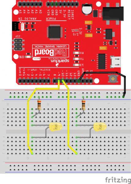
Check out the circuit diagram below to see how everything is connected.
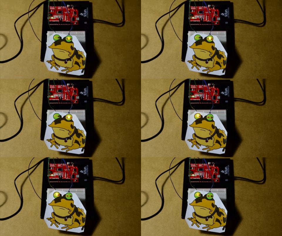
The Arduino IDE has really great entry level examples aside from blink. A favorite of mine is an LED Fade. We're going to modify it to fade two LEDs and use them as eyes. The fade function relies on analogWrite(). This function outputs a Pulse Width Modulation (PWM) signal. At low integer values the signal will make the LED dim, and will make the LED bright at high integer values.
Copy and paste the following code into the Arduino IDE. Hit upload, and see what happens!
language:c
//This example fades an LED on and off. Then the other LED will fade in and out.

//Declare pins and variables
const int ledA = 9;
const int ledB = 10;
int brightness = 0;
int fadeAmount = 5;

void setup() {

  //Declare pins as outputs
  pinMode(ledA, OUTPUT);
  pinMode(ledB, OUTPUT);
}

void loop() {

  //ledA will fade on
  for (int i = 0; i <= 255;) {
    analogWrite(ledA, brightness);
    brightness += fadeAmount;
    i += fadeAmount;
    delay(30);
  }

  //ledA will fade off
  for (int i = 255; i >= 0;) {
    analogWrite(ledA, brightness);
    brightness -= fadeAmount;
    i -= fadeAmount;
    delay(30);
  }

  //ledB will fade on
  for (int j = 0; j <= 255;) {
    analogWrite(ledB, brightness);
    brightness += fadeAmount;
    j += fadeAmount;
    delay(30);
  }

  //ledB will fade off
  for (int j = 255; j >= 0;) {
    analogWrite(ledB, brightness);
    brightness -= fadeAmount;
    j -= fadeAmount;
    delay(30);
  }

}
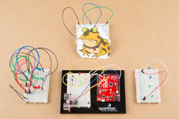
You should see one LED fade on and off. Then the other LED will fade in and out. I printed a popular cartoon image and punched holes through the eyes for the LEDs. Try searching the Internet for a fun image and make some holes yourself. You may need to adjust the size of the image and position of the LEDs to align the eyes. Go crazy with it!
Binary Counter
A not so glamorous topic in computer science are binary numbers, a.k.a the infamous 1's and 0's. When we count in binary, we represent numbers with arrangments of 1's and 0's. For example, if I wanted to write the number 4, I would need a 'binary sentence' of 0100. If you'd like to learn more about binary numbers, we have a tutorial about binary numbers that you can explore.
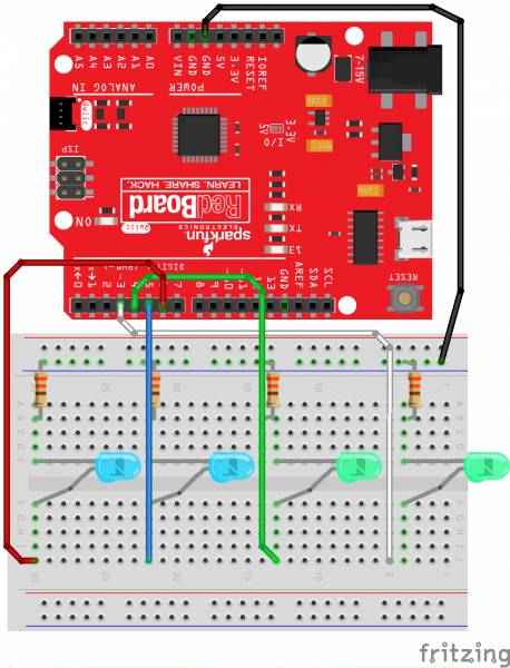
The binary project we'll run today will use the LEDs to represent 1's and 0's. An LED that's on is a 1, off will be a 0. Also, a special note about the code, we'll be using switch statements instead of if() statements. If you're not familiar with switch statements, please make sure to check out the Arduino reference language to familiarize yourself.
Check out the circuit diagram below to see how everything is connected.
Copy and paste the following code into the Arduino IDE. Hit upload, and see what happens!
language:c
//This example toggles uses LEDs as a binary counter.

//Declare pins
const int ledA = 3; //In binary, this pin will be the right-most digit or 1st position
const int ledB = 4; //2nd position
const int ledC = 5; //3rd position
const int ledD = 6; //4th position

void setup() {
  //Declare pins as outputs
  pinMode(ledA, OUTPUT);
  pinMode(ledB, OUTPUT);
  pinMode(ledC, OUTPUT);
  pinMode(ledD, OUTPUT);
}

void loop() {
  for (int i = 0; i < 16; i++) {
    switch (i) {
      case 0:  //0 = 0b0000
        delay(1000);
        digitalWrite(ledA, LOW);
        digitalWrite(ledB, LOW);
        digitalWrite(ledC, LOW);
        digitalWrite(ledD, LOW);
        break;

      case 1: //1 = 0b0001
        digitalWrite(ledA, HIGH);
        delay(1000);
        digitalWrite(ledA, LOW);
        break;

      case 2: //2 = 0b0010
        digitalWrite(ledB, HIGH);
        delay(1000);
        digitalWrite(ledB, LOW);
        break;

      case 3: //3 = 0b0011
        digitalWrite(ledA, HIGH);
        digitalWrite(ledB, HIGH);
        delay(1000);
        digitalWrite(ledA, LOW);
        digitalWrite(ledB, LOW);
        break;

      case 4: //4 = 0b0100
        digitalWrite(ledC, HIGH);
        delay(1000);
        digitalWrite(ledC, LOW);
        break;

      case 5: //5 = 0b0101
        digitalWrite(ledA, HIGH);
        digitalWrite(ledC, HIGH);
        delay(1000);
        digitalWrite(ledA, LOW);
        digitalWrite(ledC, LOW);
        break;

      case 6: //6 = 0b0110
        digitalWrite(ledB, HIGH);
        digitalWrite(ledC, HIGH);
        delay(1000);
        digitalWrite(ledB, LOW);
        digitalWrite(ledC, LOW);
        break;

      case 7: //7 = 0b0111
        digitalWrite(ledA, HIGH);
        digitalWrite(ledB, HIGH);
        digitalWrite(ledC, HIGH);
        delay(1000);
        digitalWrite(ledA, LOW);
        digitalWrite(ledB, LOW);
        digitalWrite(ledC, LOW);
        break;

      case 8: //8 = 0b1000
        digitalWrite(ledD, HIGH);
        delay(1000);
        digitalWrite(ledD, LOW);
        break;

      case 9: //9 = 0b1001
        digitalWrite(ledA, HIGH);
        digitalWrite(ledD, HIGH);
        delay(1000);
        digitalWrite(ledA, LOW);
        digitalWrite(ledD, LOW);
        break;

      case 10: //10 = 0b1010
        digitalWrite(ledB, HIGH);
        digitalWrite(ledD, HIGH);
        delay(1000);
        digitalWrite(ledB, LOW);
        digitalWrite(ledD, LOW);
        break;

      case 11: //11 = 0b1011
        digitalWrite(ledA, HIGH);
        digitalWrite(ledB, HIGH);
        digitalWrite(ledD, HIGH);
        delay(1000);
        digitalWrite(ledA, LOW);
        digitalWrite(ledB, LOW);
        digitalWrite(ledD, LOW);
        break;

      case 12: //12 = 0b1100
        digitalWrite(ledC, HIGH);
        digitalWrite(ledD, HIGH);
        delay(1000);
        digitalWrite(ledC, LOW);
        digitalWrite(ledD, LOW);
        break;

      case 13: //13 = 0b1101
        digitalWrite(ledA, HIGH);
        digitalWrite(ledC, HIGH);
        digitalWrite(ledD, HIGH);
        delay(1000);
        digitalWrite(ledA, LOW);
        digitalWrite(ledC, LOW);
        digitalWrite(ledD, LOW);
        break;

      case 14: //14 = 0b1110
        digitalWrite(ledB, HIGH);
        digitalWrite(ledC, HIGH);
        digitalWrite(ledD, HIGH);
        delay(1000);
        digitalWrite(ledB, LOW);
        digitalWrite(ledC, LOW);
        digitalWrite(ledD, LOW);
        break;

      case 15: //15 = 0b1111
        digitalWrite(ledA, HIGH);
        digitalWrite(ledB, HIGH);
        digitalWrite(ledC, HIGH);
        digitalWrite(ledD, HIGH);
        delay(1000);
        digitalWrite(ledA, LOW);
        digitalWrite(ledB, LOW);
        digitalWrite(ledC, LOW);
        digitalWrite(ledD, LOW);
        break;
    }
  }
  delay(500);
}
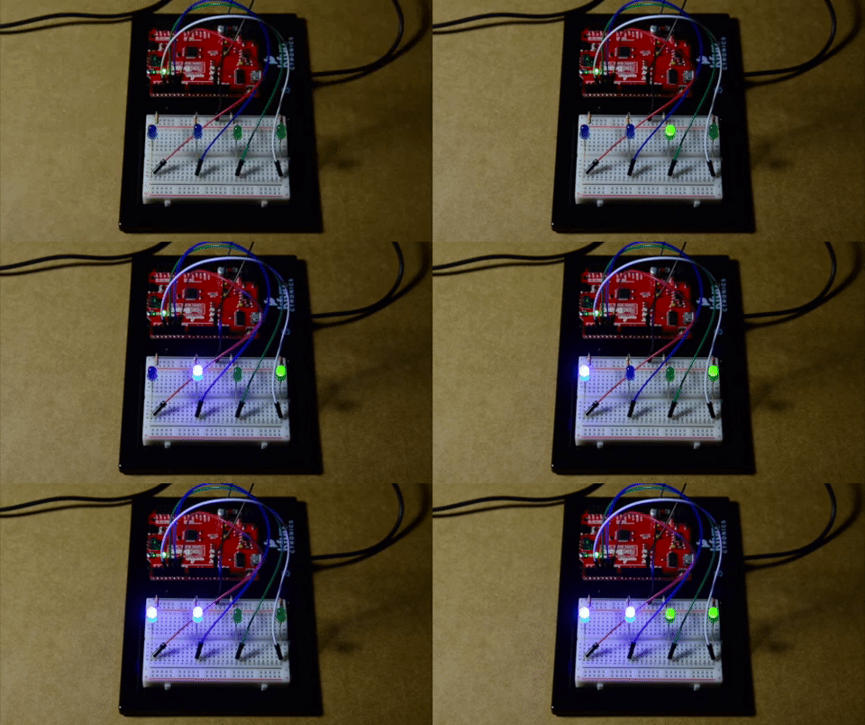
With the blue LEDs to your left, you should see the LEDs slowly count up in binary and repeat the sequence. Try adding more LEDs and switch cases to see if you can increase the binary counter!
ledD, ledC, ledB, ledA.
One for the Road
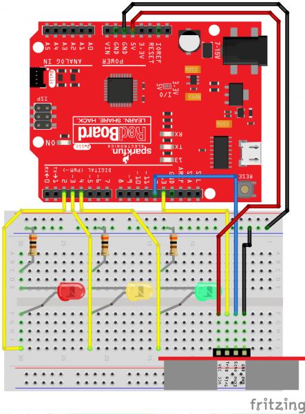
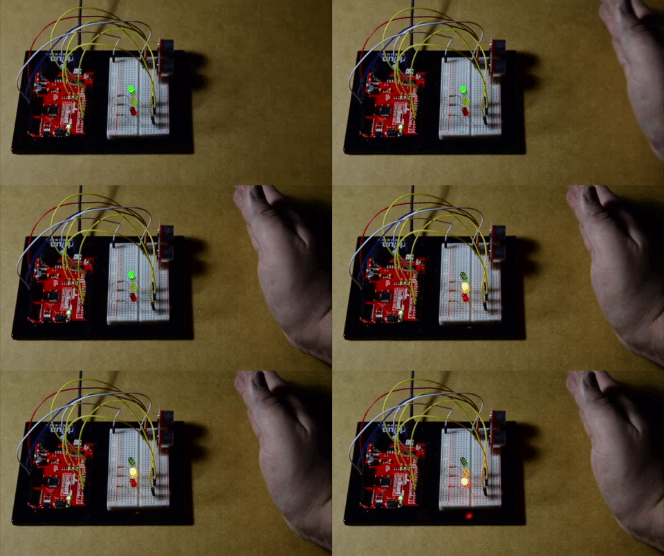
Last exercise is for a taste of using LEDs as indicators for a sensor as opposed to toggling or fading an LED. Sensor indicating lights are a very simple and effective form of user interface. So we'll trigger a 'stoplight' sequence when the proximity sensor detects something getting too close.
Check out the circuit diagram below to see how everything is connected.
Copy and paste the following code into the Arduino IDE. Hit upload, and see what happens!
language:c
//This example will trigger a 'stoplight' sequence when the proximity sensor detects something getting too close.

//Declare pins and variables
int trigger = 13;
int echo = 12;
int red = 2;
int yellow = 3;
int green = 4;

void setup() {
  Serial.begin(9600);               //Initialize serial monitor at 9600 baud
  pinMode(trigger, OUTPUT);         //Output to initiate sensor cycle
  pinMode(echo, INPUT);             //Input to do math from for distance
  pinMode(red, OUTPUT);
  pinMode(yellow, OUTPUT);
  pinMode(green, OUTPUT);

  digitalWrite(green, HIGH);
}

void loop() {
  long duration, distance;
  digitalWrite(trigger, LOW);
  delayMicroseconds(2);
  digitalWrite(trigger, HIGH);
  delayMicroseconds(10);
  digitalWrite(trigger, LOW);
  duration = pulseIn(echo, HIGH);   //Reads PWM
  distance = (duration / 2) / 29.1; //Take half of duration and divide by 29.1
  Serial.print(distance);
  Serial.println(" cm");
  delay(750);

  if (distance <= 15) {
    //Stoplight Animation
    digitalWrite(green, LOW);
    digitalWrite(yellow, HIGH);
    delay(2000);
    digitalWrite(yellow, LOW);
    digitalWrite(red, HIGH);
    delay(3500);
    digitalWrite(red, LOW);
    digitalWrite(green, HIGH);
    delay(3500);
  }
}
When the code initializes, the LED will have the green LED turned on. Once an object gets too close to the ultrasonic sensor, the stoplight sequence will start animating. This is a simplified example of how a stoplight works using an ultrasonic sensor to trigger the LEDs. Depending on the designer, a traffic control system may use image processing with cameras, radar, infrared sensors, magnetometers, or inductive loops to detect when a car is trying to cross an intersection. If a car is detected, the stoplight will trigger to notify other cars across from the intersection to slow down and stop. After a few sections, the LED will reset to green and run through the sequence again if there still is an object in front of the ultrasonic sensor.
Try adjusting the code to keep the red LED on as long as the object is in front of the ultrasonic sensor as opposed to reseting to green. The circuit is just a miniature prototype of a traffic control system. Try mounting the LEDs in a cardboard enclosure to make your own miniature intersection for two, one-way streets. Then try adding more LEDs and adjusting the code to control LEDs for a four-way intersection.
Resources and Going Further
For more information, check out the resources below.
- How to Use a Multimeter
- Pulse Width Modulation
- Binary
- Arduino.cc
- Stoplight
LEDs can be fun and easy to add to any circuit. There are tons of options! Power indicators, signal indicators, or just downright cool lighting effects. Play around with the Arduino code and make some cool effects. Maybe some illumination may spark something even better. Need some inspiration for your next project? Check out some of these related tutorials using LEDs.
Pulse Width Modulation
The Great Big Guide to Paper Circuits
BadgerHack: Gaming Add-On Kit
LP55231 Breakout Board Hookup Guide
