SX1509 I/O Expander Breakout Hookup Guide
 jimblom
 Introduction
Is your Arduino running low on GPIO? Looking to control the brightness of 16 LEDs individually? Maybe blink or breathe a few autonomously? Want to delegate scanning an 8x8 matrix of 64 buttons to another controller? These are all tasks the for which the SX1509 16-IO Expander was made!
The SX1509 is a 16-channel GPIO expander with an I2C interface -- that means with just two wires, your microcontroller can interface with 16 fully configurable digital input/output pins.
But, the SX1509 can do so much more than just simple digital pin control. It can produce PWM signals, so you can dim LEDs. It can be set to blink or even breathe pins at varying rates. And, with a built-in keypad engine, it can interface with up to 64 buttons set up in an 8x8 matrix.
It's a really cool chip and a great tool for expanding the capability of your Arduino or any other I2C-capable microcontroller.
Covered In this Tutorial
This tutorial will serve to familiarize you with all things SX1509 and the SparkFun Breakout. Then we'll demonstrate how take advantage of all of the I/O expander's features using an Arduino-compatible microcontroller and our SX1509 Arduino Library.
The tutorial is split into the following sections:
- SX1509 Breakout Board Overview -- An overview of the features of the SX1509 and the SparkFun breakout.
- Hardware Assembly -- Tips and tricks for soldering headers or wires to the SX1509 Breakout.
- Installing the SparkFun SX1509 Arduino Library -- We've written an Arduino library to abstract all of the ugly register bit-operations.
- Example: Digital In/Out and PWM -- An example circuit and Arduino sketch demonstrating some of the simpler I/O expander features.
- Example: LED Driving -- Examples demonstrating how to autonomously blink and breathe LEDs.
- Example: Button Matrices -- How to use the SX1509's keypad engine to monitor a 12-button keypad.
Suggested Reading
Before delving into this tutorial, there are a few concepts you should already be somewhat familiar with. Check out these related tutorials:
- I2C Communication -- The SX1509 is controlled over an I2C interface. Learn all about this powerful 2-wire interface.
- Logic Levels -- While most Arduino's operate at 5V, the SX1509 works at 3.3V. The GPIO are, at least, 5V tolerant!
- Pulse-Width Modulation (PWM) -- All of the SX1509's output pins are capable of producing a PWM signal. That means you can control the brightness of LEDs!
Pulse Width Modulation
Logic Levels
Light-Emitting Diodes (LEDs)
I2C
SX1509 Breakout Board Overview
There's a lot going on on the SX1509 Breakout. GPIO and power buses are broken out in every-which direction, and configurable jumpers cover most of the rest of the board.
This section will cover all things SX1509 Breakout, so you can get the most out of the board's features.
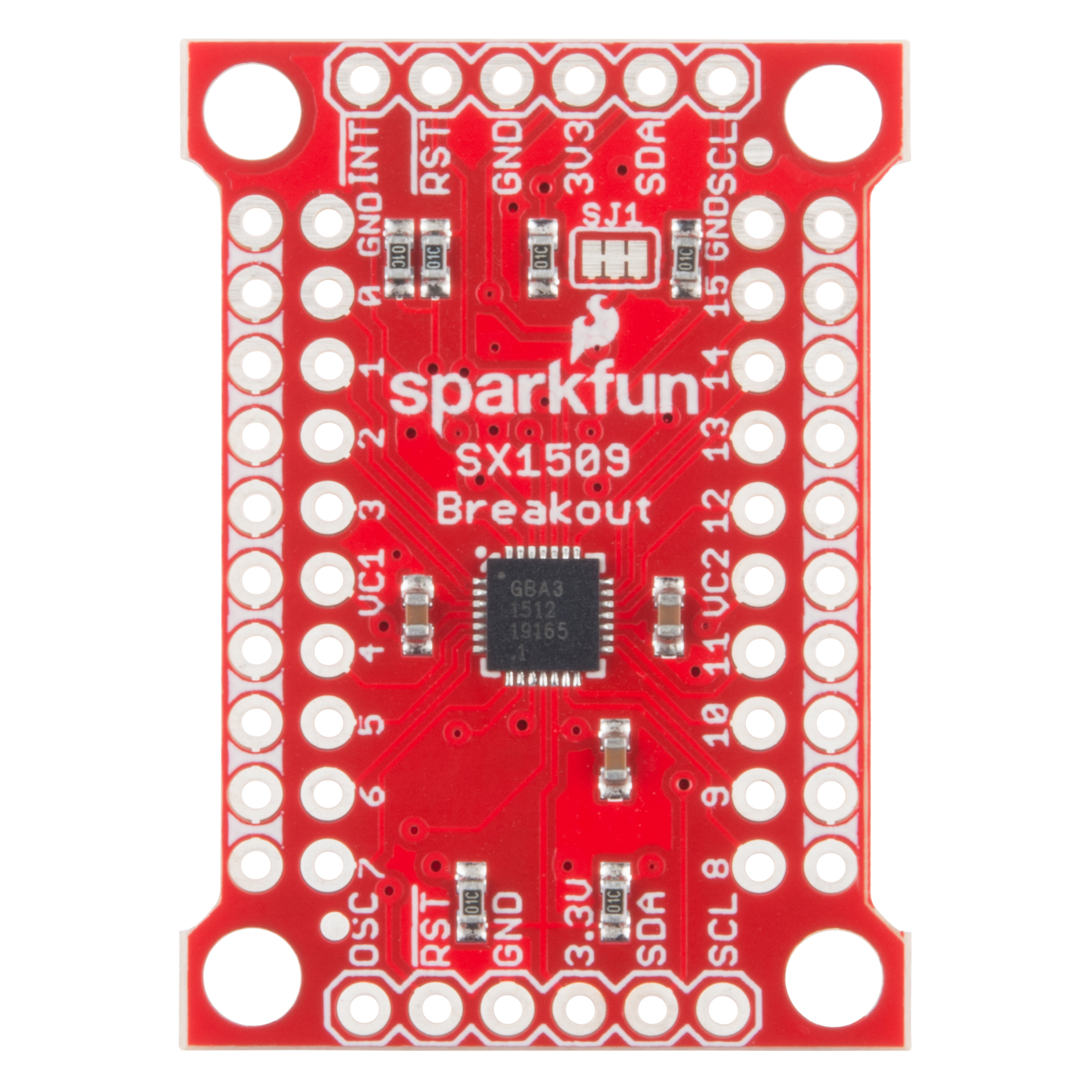
I2C and Power Input Headers
These two headers at the top and bottom of the breakout board are the input and control headers to the board. This is where you can supply power to the SX1509, and where your I2C signals -- SDA and SCL -- will terminate.
These headers break out the following pins:
| Pin Label | Type | Description |
|---|---|---|
| INT | Output | Active low programmable interrupt |
| RST | Input | Active low reset (pulled high on-board) |
| GND | Power | Ground (0V) |
| 3V3 | Power | Main supply voltage (1.425-3.6V) |
| SDA | I2C | I2C serial data line |
| SCL | I2C | I2C serial clock line |
| OSC | Clock In/Out | Optional clock input, or programmable clock signal output |
The SDA and SCL pins each have 10kΩ resistors pulling them up to 3.3V. These resistors can be disconnected by cutting the SJ1 jumpers.
RST -- the SX1509's active-low reset input -- works just like an Arduino reset pin. If the pin is pulled LOW, the SX1509 will power down. When RST rises, the SX1509 will turn back on, but all of its settings will be cleared out. The breakout board includes a 10kΩ resistor pulling RST HIGH, so you ignore this pin if you don't need the reset functionality.
INT is a very handy interrupt output, especially if you're using any SX1509 pins as inputs. It can be configured to go LOW whenever a pin state changes. The breakout board includes a 10kΩ resistor pulling INT HIGH.
Finally, OSC breaks out the SX1509's OSCIO pin -- the oscillator input/output. This highly-configurable pin can be used as either the clock input for the SX1509 (if you don't want to use its internal 2MHz clock), a clock output (producing an up to 2MHz square wave signal), or a simple digital I/O.
I/O and GND/VCC Breakouts
The real meat of the breakout board are the pairs of rows breaking out all sixteen I/O pins plus the power rails.
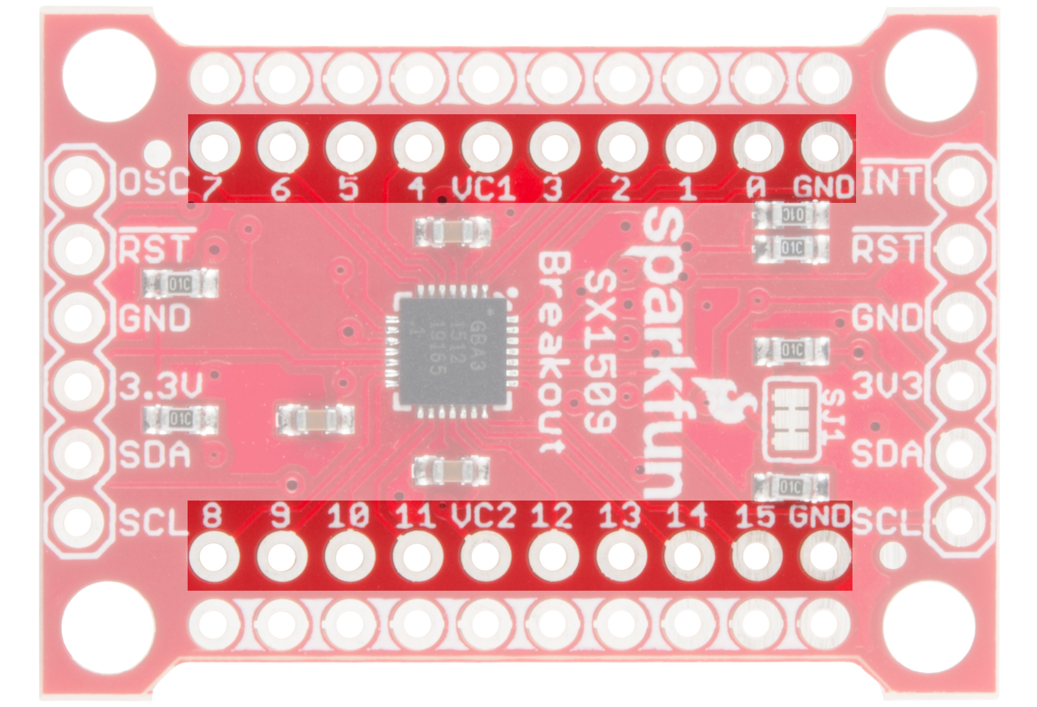
The SX1509 breaks its 16 I/O into two banks -- bank A and bank B. Each bank can operate on a separate power supply, but by default they're both set to 3.3V. Bank A is powered by VCC1, and bank B is supplied by VCC2. VCC1 and VCC2 can range between 1.2V and 3.6V, if you want to supply them externally. Check out the "Jumpers" section for more information on that.
Every I/O pin is capable of PWM and blink outputs, but only half of them can be set to "breathe" (blink with smooth transitions from on to off). Also, if you plan on using the SX1509 keypad driver, each I/O is relegated to either a row or column interface.
| LED Driver | Keypad | ||||
|---|---|---|---|---|---|
| I/O | PWM | Blink | Breathe | Row | Column |
| 0 | ✓ | ✓ | ✓ | ||
| 1 | ✓ | ✓ | ✓ | ||
| 2 | ✓ | ✓ | ✓ | ||
| 3 | ✓ | ✓ | ✓ | ||
| 4 | ✓ | ✓ | ✓ | ✓ | |
| 5 | ✓ | ✓ | ✓ | ✓ | |
| 6 | ✓ | ✓ | ✓ | ✓ | |
| 7 | ✓ | ✓ | ✓ | ✓ | |
| 8 | ✓ | ✓ | ✓ | ||
| 9 | ✓ | ✓ | ✓ | ||
| 10 | ✓ | ✓ | ✓ | ||
| 11 | ✓ | ✓ | ✓ | ||
| 12 | ✓ | ✓ | ✓ | ✓ | |
| 13 | ✓ | ✓ | ✓ | ✓ | |
| 14 | ✓ | ✓ | ✓ | ✓ | |
| 15 | ✓ | ✓ | ✓ | ✓ | |
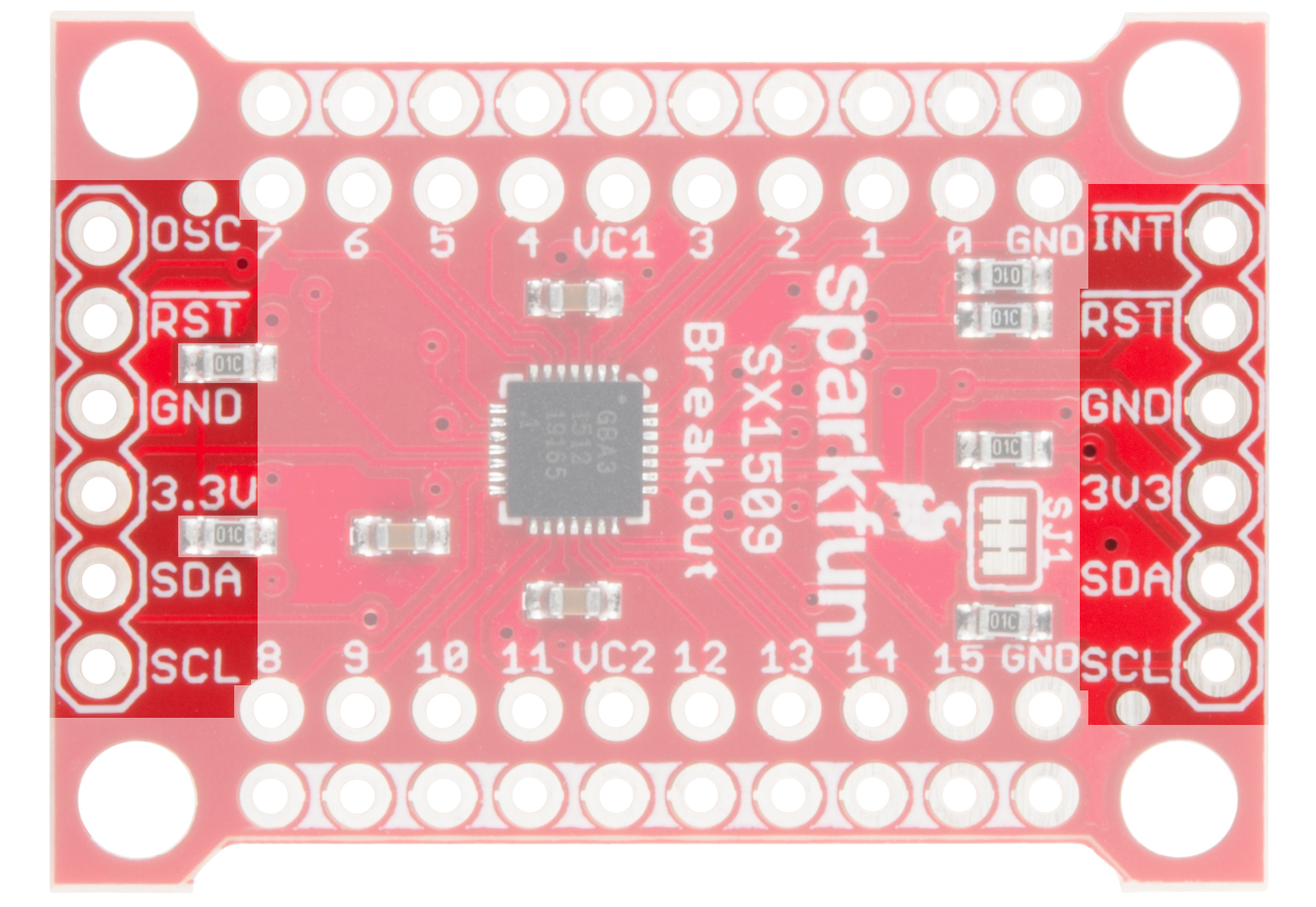
Ground (or Power) Rails
Running alongside the I/O breakouts are a pair of power rails. These rails can be distinguished by the bars of white silkscreen running between each pad.

By default, these rails are both set to ground -- handy if you want to fan out some active-low buttons, or current-sourced LEDs. Jumpers on the back side allow you to switch the rails from GND to either VCC1 or VCC2. You'll need to cut the jumper between GND and the rail, then blob solder between the rail and VCC.
This bus is completely optional. Just don't solder male pins into both rows of headers if you plan on using the breakout in a breadboard!
Address-Select Jumpers
Up to four SX1509's can be connected to a single I2C bus, by configuring them to different addresses. The SX1509 has two pins devoted to I2C address selection: ADD0 and ADD1. Each of those pins are broken out to a jumper on the bottom of the board.
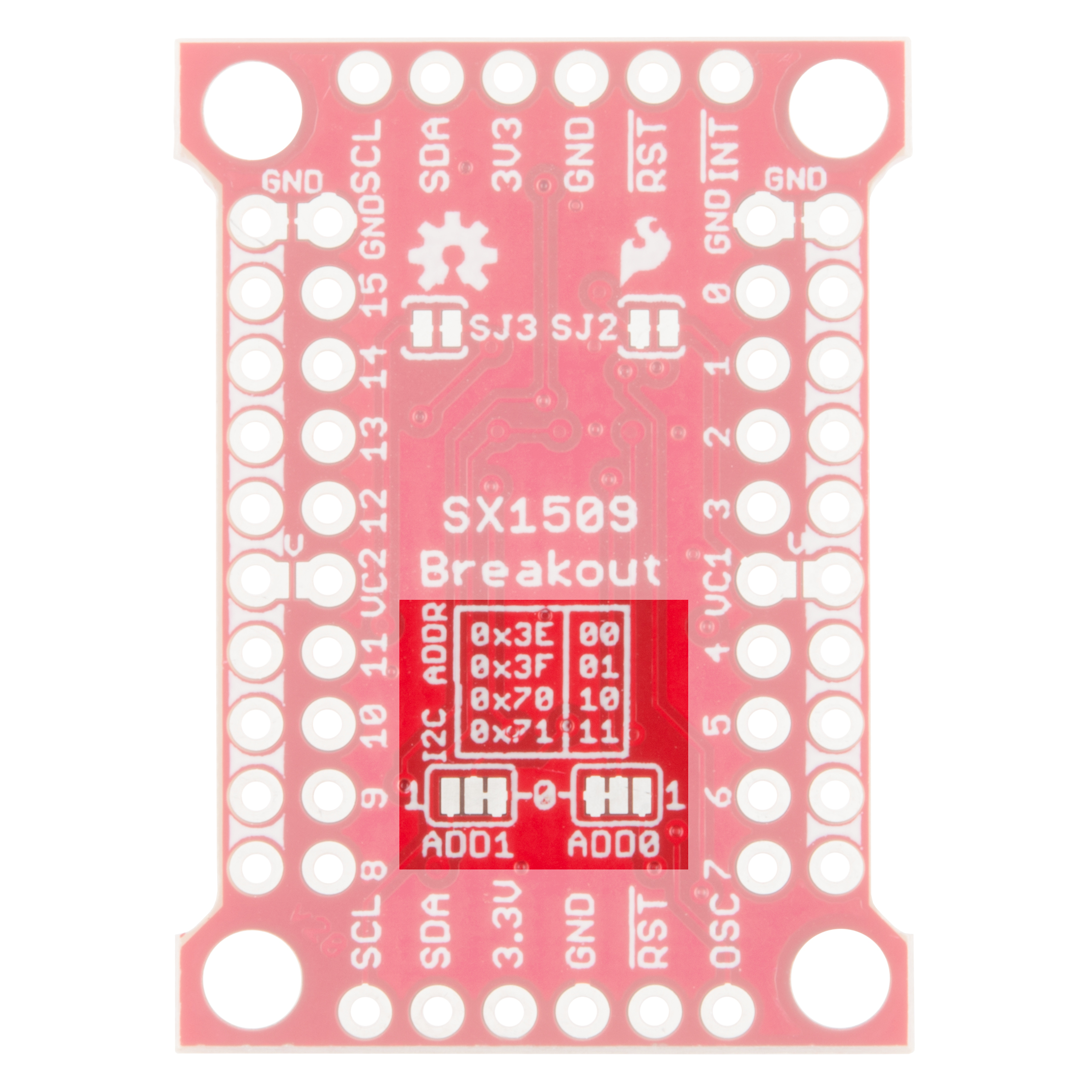
The board defaults each of those pins to GND, which sets the I2C address to 0x3E. To set either jumper to "1" (HIGH), grab a hobby knife, cut the trace connecting to "0", and blob some solder between the center pad and "1".
The four configurable addresses are listed on the back of the board, but for quick reference, they are:
| ADD1 | ADD0 | I2C address |
|---|---|---|
| 0 | 0 | 0x3E |
| 0 | 1 | 0x3F |
| 1 | 0 | 0x70 |
| 1 | 1 | 0x71 |
VCC1 and VCC2 Jumpers
SJ2 and SJ3 on the back-side of the board connect VCC2 and VCC1, respectively, to the 3V3 voltage supply input. So, if you're delivering 3.3V to the board, each of the I/O banks will operate at 3.3V.
If you want to take advantage of the SX1509's level-shifting capabilities by powering these banks at something other than VCC, cut the jumpers and plug any voltage between 1.2V and 3.6V into the VCC1 and/or VCC2 pins.
These supply buses are completely independent -- so they can operate at different voltages.
Hardware Assembly
You'll need to solder something into the SX1509 Breakout to use it, whether that something is male or female headers or wire is completely up to you and your intended application. If you've never soldered before, check out our PTH soldering tutorial.
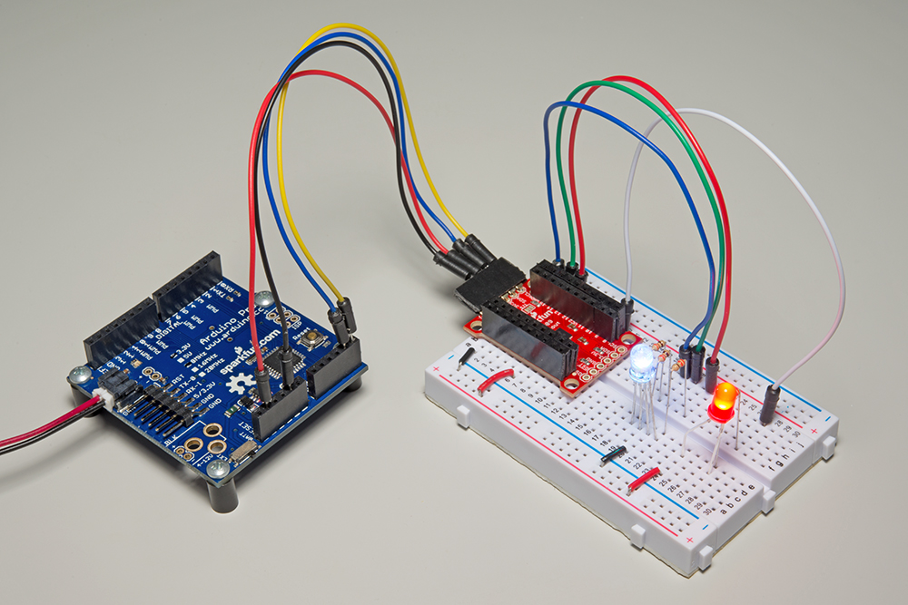
One option we like, which keeps the board as breadboard-compatible as can be, is soldering male headers on the I/O banks, and female headers on either (or both) of the power/I2C headers.
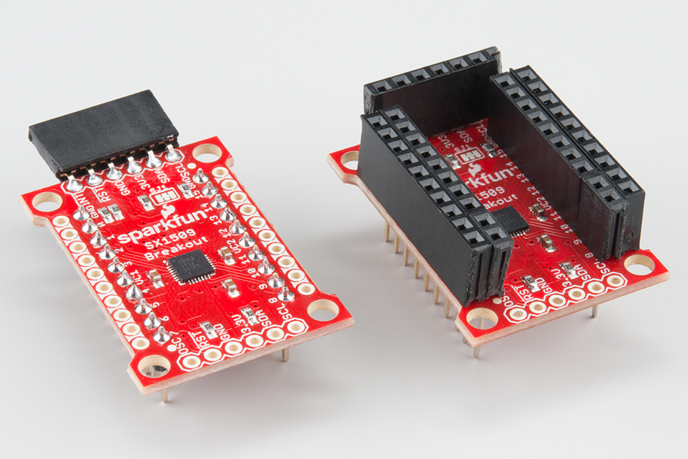
Then you can use male-to-male jumper wires to connect between your microcontroller and the breakout, and breadboard the rest of the I/O.
Installing the SparkFun SX1509 Arduino Library
Now that you've got the hardware all mostly figured out, it's time to start programming! To help make using the SX1509 as painless as possible, we've written an Arduino library to help interface with it. Open the Arduino Library Manager and search for SparkFun SX1509. You can also manually install the SparkFun SX1509 Arduino Library from the GitHub repository by clicking on the button below to download the latest version of the library.
For help installing the library, check out our Installing an Arduino Library tutorial. If you downloaded the library as a ZIP, you can use Arduino's Sketch > Include Library > Add .ZIP Library tool to automatically add it to your Arduino sketchbook.
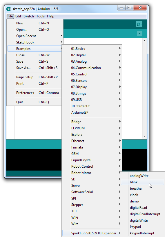
The SparkFun SX1509 Arduino library includes all sorts of examples, which demonstrate specific features of the I/O expander. Navigate to File > Examples > SparkFun SX1509 IO Expander to check them out.
Quickly, we'll walk you through a few quick examples that show off the I/O expander's range of features.
Example: Digital In/Out and PWM
As with almost any I/O expander, each of the SX1509's GPIO can be configured as simple digital inputs or outputs. So you can toggle LEDs on or off, monitor for button presses, or even bit-bang more advanced digital interfaces like SPI (probably nothing that's timing-dependent though).
Here's a quick example that shows how you can digitalWrite or digitalRead using the SX1509. If you want to follow along, hook up a circuit like below:
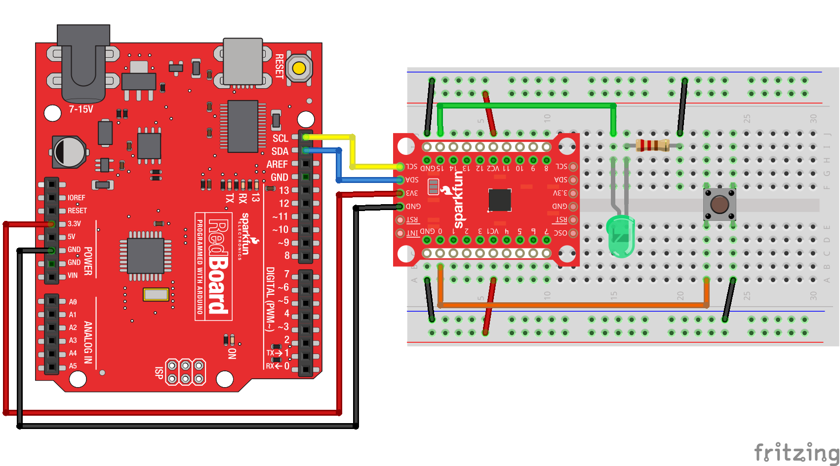
Match up 3.3V, GND, SDA, and SCL between your Arduino and the SX1509 Breakout. Then connect an LED to I/O 15 -- you can either configure it to source or sink current. And connect an active-low button to I/O 0.
Then throw this code onto your Arduino:
language:c
/*************************************************************
  digitalReadWrite_Combined.ino
  SparkFun SX1509 I/O Expander Example: digital I/O (digitalRead/digitalWrite)
  Jim Lindblom @ SparkFun Electronics
  Original Creation Date: September 21, 2015
  https://github.com/sparkfun/SparkFun_SX1509_Arduino_Library

  This example demonstrates the SX1509's digitalRead and digitalWrite
  functionality. We'll attach an active-low button to an
  INPUT_PULLUP input and attach an LED to a pin set as an OUTPUT.
  Then whenever the button read's LOW, we'll toggle the LED.
  Note that the code will wait until the button is released
  before reading the SX1509 pins again.

  After uploading the sketch, open your serial monitor and set
  it to 115200 baud.

  Hardware Hookup:
  SX1509 Breakout ------ Arduino -------- Breadboard
        GND -------------- GND
        3V3 -------------- 3.3V
        SDA ------------ SDA (A4)
        SCL ------------ SCL (A5)
        0 ---------------------------------]BTN[----GND
        15 -------------------------------- LED+
                                       LED- -/\/\/\- GND
                                               330
  Development environment specifics:
  IDE: Arduino 1.6.5
  Hardware Platform: Arduino Uno
  SX1509 Breakout Version: v2.0

  This code is beerware; if you see me (or any other SparkFun
  employee) at the local, and you've found our code helpful,
  please buy us a round!

  Distributed as-is; no warranty is given.
*************************************************************/

#include <Wire.h>           // Include the I2C library (required)
#include <SparkFunSX1509.h> //Click here for the library: http://librarymanager/All#SparkFun_SX1509

// SX1509 I2C address (set by ADDR1 and ADDR0 (00 by default):
const byte SX1509_ADDRESS = 0x3E; // SX1509 I2C address
SX1509 io;                        // Create an SX1509 object to be used throughout

// SX1509 pin definitions:
// Note: these aren't Arduino pins. They're the SX1509 I/O:
const byte SX1509_LED_PIN = 15; // LED connected to 15 (source ing current)
const byte SX1509_BUTTON_PIN = 0; // Button connected to 0 (Active-low button)

bool ledState = false;

void setup()
{
  // Serial is used in this example to display the input value
  // of the SX1509_INPUT_PIN input:
  Serial.begin(115200);
  Serial.println("SX1509 Example");

  Wire.begin(); //Initialize I2C bus

  pinMode(13, OUTPUT); // Use pin 13 LED as debug output
  digitalWrite(13, LOW); // Start it as low


  // Call io.begin(<address>) to initialize the SX1509. If it
  // successfully communicates, it'll return 1.
  if (io.begin(SX1509_ADDRESS) == false)
  {
    Serial.println("Failed to communicate. Check wiring and address of SX1509.");
    digitalWrite(13, HIGH); // If we failed to communicate, turn the pin 13 LED on
    while (1)
      ; // If we fail to communicate, loop forever.
  }

  // Call io.pinMode(<pin>, <mode>) to set any SX1509 pin as
  // either an INPUT, OUTPUT, INPUT_PULLUP, or ANALOG_OUTPUT
  // Set output for LED:
  io.pinMode(SX1509_LED_PIN, OUTPUT);
  // Use a pull-up resistor on the button's input pin. When
  // the button is pressed, the pin will be read as LOW:
  io.pinMode(SX1509_BUTTON_PIN, INPUT_PULLUP);

  // Blink the LED a few times before we start:
  for (int i = 0; i < 5; i++)
  {
    // Use io.digitalWrite(<pin>, <LOW | HIGH>) to set an
    // SX1509 pin either HIGH or LOW:
    io.digitalWrite(SX1509_LED_PIN, HIGH);
    delay(100);
    io.digitalWrite(SX1509_LED_PIN, LOW);
    delay(100);
  }
}

void loop()
{
  // Use io.digitalRead() to check if an SX1509 input I/O is
  // either LOW or HIGH.
  if (io.digitalRead(SX1509_BUTTON_PIN) == LOW)
  {
    // Print the status of the other pin:
    Serial.print("SX1509_BUTTON_PIN status: ");
    // Read the pin to print either 0 or 1
    Serial.println(io.digitalRead(SX1509_BUTTON_PIN));

    // If the button is pressed toggle the LED:
    ledState = !ledState;
    io.digitalWrite(SX1509_LED_PIN, ledState);

    // Print the status of the other pin:
    Serial.print("SX1509_LED_PIN status: ");
    // Read the pin to print either 0 or 1
    Serial.println(ledState);


    Serial.print("Waiting for button to release...");
    while (io.digitalRead(SX1509_BUTTON_PIN) == LOW)
      ; // Wait for button to release
    Serial.println("Button released!");

    //delay(200); //uncomment to add a small delay for  button debouncing
  }
}
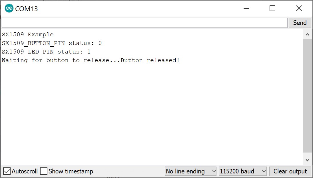
When you press the button down, the LED state should toggle. Opening the Arduino Serial Monitor at 115200 will also give you the serial output. Check through the code to see how easy it is! Not all that different from Arduino code you may already be familiar with.
Getting Started with the SX1509 Library
To begin, include the "SparkFunSX1509.h" library (and the "Wire.h" library as well), and create an SX1509 object in the global area:
language:c
#include <Wire.h>           // Include the I2C library (required)
#include <SparkFunSX1509.h> //Click here for the library: http://librarymanager/All#SparkFun_SX1509

// SX1509 I2C address (set by ADDR1 and ADDR0 (00 by default):
const byte SX1509_ADDRESS = 0x3E; // SX1509 I2C address
SX1509 io;                        // Create an SX1509 object to be used throughout
You'll use that io object from here on out. In the setup(), make sure to join the I2C bus using Wire.begin(). To initialize the I/O expander -- and to make sure it's communicating correctly -- you will then need to call io.begin(<address>), where <address> is the I2C address of the expander (0x3E by default). In this case, we defined SX1509_ADDRESS earlier in the code. Check the return value of begin() to make sure everything is hunky-dory.
language:c
  Wire.begin(); //Initialize I2C bus

  pinMode(13, OUTPUT); // Use pin 13 LED as debug output
  digitalWrite(13, LOW); // Start it as low


  // Call io.begin(<address>) to initialize the SX1509. If it
  // successfully communicates, it'll return 1.
  if (io.begin(SX1509_ADDRESS) == false)
  {
    Serial.println("Failed to communicate. Check wiring and address of SX1509.");
    digitalWrite(13, HIGH); // If we failed to communicate, turn the pin 13 LED on
    while (1)
      ; // If we fail to communicate, loop forever.
  }
Wire.begin()must be called explicitly within the Arduino sketch beforeio.begin()is called. This may break code that does not haveWire.begin().io.begin()has been expanded to includeio.begin(deviceAddress, wirePort, resetPin). This may break code whereresetPinwas the 2nd argument.
Then you can use functions you should already be mostly familiar with to control the I/O. Just tag the io object onto the beginning of pinMode, digitalWrite and digitalRead, and go about your Arduino-business as normal!
Analog Output (PWM)
You can also use any I/O as an "analog" (PWM) output by using the analogWrite(<pin>, <0-255>) function -- just like Arduino analog output! There are just a couple differences to be aware of:
- ANALOG_OUTPUT: If you want a pin to produce PWM signals, call
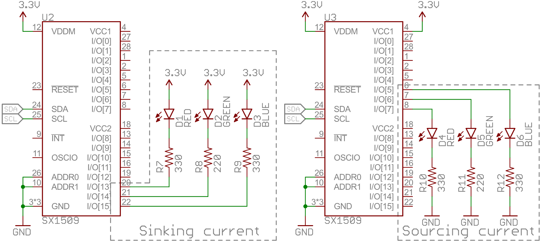
pinMode(<pin>, ANALOG_OUTPUT)in your setup. That will tell the SX1509 to initialize the pin as an "LED driver". - Sinking Current:
analogWrite(<pin>, <0-255>)assumes that the LED is hooked up in a current-sinking fashion -- meaning the LED's cathode (negative pin) is terminated into the SX1509. Thus,analogWriteing to 255 will actually pull the pin LOW, and 0 will set it HIGH.
Here's some example code:
language:c
/*************************************************************
  analogWrite.ino
  SparkFun SX1509 I/O Expander Example: pwm output (analogWrite)
  Jim Lindblom @ SparkFun Electronics
  Original Creation Date: September 21, 2015
  https://github.com/sparkfun/SparkFun_SX1509_Arduino_Library

  This example demonstrates the SX1509's analogWrite function.
  Connect an LED to the SX1509's pin 15 (or any other pin, they
  can all PWM!). The SX1509 can either sink or source current,
  just don't forget your limiting resistor!

  Hardware Hookup:
  SX1509 Breakout ------ Arduino -------- Breadboard
        GND -------------- GND
        3V3 -------------- 3.3V
      SDA ------------ SDA (A4)
      SCL ------------ SCL (A5)
      15 -------------------------------- LED+
                                     LED- -/\/\/\- GND
                                                330

  Development environment specifics:
  IDE: Arduino 1.6.5
  Hardware Platform: Arduino Uno
  SX1509 Breakout Version: v2.0

  This code is beerware; if you see me (or any other SparkFun
  employee) at the local, and you've found our code helpful,
  please buy us a round!

  Distributed as-is; no warranty is given.
*************************************************************/

#include <Wire.h>           // Include the I2C library (required)
#include <SparkFunSX1509.h> //Click here for the library: http://librarymanager/All#SparkFun_SX1509

// SX1509 I2C address (set by ADDR1 and ADDR0 (00 by default):
const byte SX1509_ADDRESS = 0x3E; // SX1509 I2C address
SX1509 io;                        // Create an SX1509 object to be used throughout

// SX1509 Pin definition:
const byte SX1509_LED_PIN = 15; // LED to SX1509's pin 15

void setup()
{
  Serial.begin(115200);
  Serial.println("SX1509 Example");

  Wire.begin();

  // Call io.begin(<address>) to initialize the SX1509. If it
  // successfully communicates, it'll return 1.
  if (io.begin(SX1509_ADDRESS) == false)
  {
    Serial.println("Failed to communicate. Check wiring and address of SX1509.");
    while (1)
      ; // If we fail to communicate, loop forever.
  }

  // Use the pinMode(<pin>, <mode>) function to set our led
  // pin as an ANALOG_OUTPUT, which is required for PWM output
  io.pinMode(SX1509_LED_PIN, ANALOG_OUTPUT);
}

void loop()
{
  // Ramp brightness up, from 0-255, delay 2ms in between
  // analogWrite's
  for (int brightness = 0; brightness < 256; brightness++)
  {
    // Call io.analogWrite(<pin>, <0-255>) to configure the
    // PWM duty cycle
    io.analogWrite(SX1509_LED_PIN, brightness);
    delay(2); // Delay 2 milliseconds
  }
  delay(500); // Delay half-a-second

  // Ramp brightness down, from 255-0, delay 2ms in between
  // analogWrite's
  for (int brightness = 255; brightness >= 0; brightness--)
  {
    io.analogWrite(SX1509_LED_PIN, brightness);
    delay(2); // Delay 2 milliseconds
  }
  delay(500); // Delay half-a-second
}
That's a real fine breathing LED! But the SX1509 is so much more than a simple digital I/O expander. Its LED-driving capabilities mean you can offload all of that breathing to the SX1509, leaving your loop() for more important tasks!
Example: LED Driving
One of the SX1509's coolest features is its built-in LED-driving support. Beyond digital or even PWM output, the SX1509 can also autonomously blink or breathe LEDs! Just tell it how long to blink, or how fast to rise/fall, and it'll do the rest for you.
For this example, grab four LEDs and wire them up to pins 8, 13, 14, and 15.
Here's an example that sets an LED tied to pin 15 to blink:
language:c
/*************************************************************
blink.ino
SparkFun SX1509 I/O Expander Example: blink output
Jim Lindblom @ SparkFun Electronics
Original Creation Date: September 21, 2015
https://github.com/sparkfun/SparkFun_SX1509_Arduino_Library

This example demonstrates the SX1509's set-it-and-forget-it
blink function. We'll set the pin up as an OUTPUT, and call
io.blink() all in setup(), then watch the LED blink by itself
in loop().

Hardware Hookup:
    SX1509 Breakout ------ Arduino -------- Breadboard
          GND -------------- GND
          3V3 -------------- 3.3V
          SDA ------------ SDA (A4)
          SCL ------------ SCL (A5)
          15 -------------------------------- LED+
                                         LED- -/\/\/\- GND
                                                330

Development environment specifics:
    IDE: Arduino 1.6.5
    Hardware Platform: Arduino Uno
    SX1509 Breakout Version: v2.0

This code is beerware; if you see me (or any other SparkFun
employee) at the local, and you've found our code helpful,
please buy us a round!

Distributed as-is; no warranty is given.
*************************************************************/

#include <Wire.h>           // Include the I2C library (required)
#include <SparkFunSX1509.h> //Click here for the library: http://librarymanager/All#SparkFun_SX1509

// SX1509 I2C address (set by ADDR1 and ADDR0 (00 by default):
const byte SX1509_ADDRESS = 0x3E; // SX1509 I2C address
SX1509 io;                        // Create an SX1509 object to be used throughout

// SX1509 Pin definition:
const byte SX1509_LED_PIN = 15; // LED to SX1509's pin 15

void setup()
{
  Serial.begin(115200);
  Serial.println("SX1509 Example");

  Wire.begin();

  // Call io.begin(<address>) to initialize the SX1509. If it
  // successfully communicates, it'll return 1.
  if (io.begin(SX1509_ADDRESS) == false)
  {
    Serial.println("Failed to communicate. Check wiring and address of SX1509.");
    while (1)
      ; // If we fail to communicate, loop forever.
  }

  // Set up the SX1509's clock to use the internal 2MHz
  // oscillator. The second parameter divides the oscillator
  // clock to generate a slower LED clock. 4 divides the 2MHz
  // clock by 2 ^ (4-1) (8, ie. 250kHz). The divider parameter
  // can be anywhere between 1-7.
  io.clock(INTERNAL_CLOCK_2MHZ, 4);

  io.pinMode(SX1509_LED_PIN, OUTPUT); // Set LED pin to OUTPUT

  // Blink the LED pin -- ~1000 ms LOW, ~500 ms HIGH:
  io.blink(SX1509_LED_PIN, 1000, 500);
  // The timing parameters are in milliseconds, but they
  // aren't 100% exact. The library will estimate to try to
  // get them as close as possible. Play with the clock
  // divider to maybe get more accurate timing.
}

void loop()
{
  // Relax! The SX1509's got this...
}
The io.blink(<pin>, <low_ms>, <high_ms>) function works most of the magic in this example -- setting the LED pin to blink LOW for 1000ms and HIGH for 500ms. Those timing values will not end up being exact. The SX1509's timing mechanism is dependent on dividing the clock (we're using the internal 2MHz oscillator), and doesn't always divide down perfectly.
Before configuring the pin to blink, we call io.clock(<source>, <divider>) to set the clock that drives our LEDs. In this example we use the SX1509's internal 2MHz clock as the source, and divide that down to 250kHz for the LED clock. Play with that second parameter to see just how much the blink timing depends on it.
Try using the blink function to blink the other LEDs!
LED Breathing
Half of the SX1509's I/O pins are capable of producing "breathing" outputs -- where a pin fades in and out at a set rate. Pins 4-7 and 12-15 have this capability.
Using the same circuit as before, here's a quick example showing off the SX1509's breathe feature:
language:c
/*************************************************************
breathe.ino
SparkFun SX1509 I/O Expander Example: breathe output
Jim Lindblom @ SparkFun Electronics
Original Creation Date: September 21, 2015
https://github.com/sparkfun/SparkFun_SX1509_Arduino_Library

This example demonstrates the SX1509's set-it-and-forget-it
breathe function. The SX1509 will pulse an LED, smoothly
ramping its brightness up-then-down. We'll set the pin up as
an ANALOG_OUTPUT, and call io.breathe() all in setup(), then
watch the LED pulse by itself in loop().

Hardware Hookup:
    SX1509 Breakout ------ Arduino -------- Breadboard
          GND -------------- GND
          3V3 -------------- 3.3V
          SDA ------------ SDA (A4)
          SCL ------------ SCL (A5)
          15 --------------------------------- LED+
                                         LED- -/\/\/\- GND
                                                330

Development environment specifics:
    IDE: Arduino 1.6.5
    Hardware Platform: Arduino Uno
    SX1509 Breakout Version: v2.0

This code is beerware; if you see me (or any other SparkFun
employee) at the local, and you've found our code helpful,
please buy us a round!

Distributed as-is; no warranty is given.
*************************************************************/

#include <Wire.h>           // Include the I2C library (required)
#include <SparkFunSX1509.h> //Click here for the library: http://librarymanager/All#SparkFun_SX1509

// SX1509 I2C address (set by ADDR1 and ADDR0 (00 by default):
const byte SX1509_ADDRESS = 0x3E; // SX1509 I2C address
SX1509 io;                        // Create an SX1509 object to be used throughout

// SX1509 Pin definition:
const byte SX1509_LED_PIN = 15; // LED to SX1509's pin 15

void setup()
{
  Serial.begin(115200);
  Serial.println("SX1509 Example");

  Wire.begin();

  // Call io.begin(<address>) to initialize the SX1509. If it
  // successfully communicates, it'll return 1.
  if (io.begin(SX1509_ADDRESS) == false)
  {
    Serial.println("Failed to communicate. Check wiring and address of SX1509.");
    while (1)
      ; // If we fail to communicate, loop forever.
  }

  // Use the internal 2MHz oscillator.
  // Set LED clock to 500kHz (2MHz / (2^(3-1)):
  io.clock(INTERNAL_CLOCK_2MHZ, 3);

  // To breathe an LED, make sure you set it as an
  // ANALOG_OUTPUT, so we can PWM the pin:
  io.pinMode(SX1509_LED_PIN, ANALOG_OUTPUT);

  // Breathe an LED: 1000ms LOW, 500ms HIGH,
  // 500ms to rise from low to high
  // 250ms to fall from high to low
  io.breathe(SX1509_LED_PIN, 1000, 500, 500, 250);
  // The timing parameters are in milliseconds, but they
  // aren't 100% exact. The library will estimate to try to
  // get them as close as possible. Play with the clock
  // divider to maybe get more accurate timing.
}

void loop()
{
  // Enjoy your hypnotically breathing LED!
}
Make sure you set the pin as an ANALOG_OUTPUT using the pinMode() function. Then call io.breathe(<pin>, <low_ms>, <high_ms>, <rise_ms>, <fall_ms) to set the LOW and HIGH time as well as the number of milliseconds it takes to rise from LOW to HIGH and fall from HIGH to LOW.
Easy-peasy! And now you have the loop() left free for more important tasks. (As if! Nothing's more important than blinking LEDs.)
Example: Button Matrices
Blinking and breathing LEDs can be fun, but the SX1509's real power lies in its keypad engine. By wiring up buttons in a row/column matrix, you can connect up to 64 buttons to the SX1509.
Keypad matrices are very common -- they allow you to save immensely on GPIO. You could monitor a 16-button, 4x4 keypad pad with 8 I/O, or four of those keypads (a 64-button/8x8 matrix) with just 16 I/O.
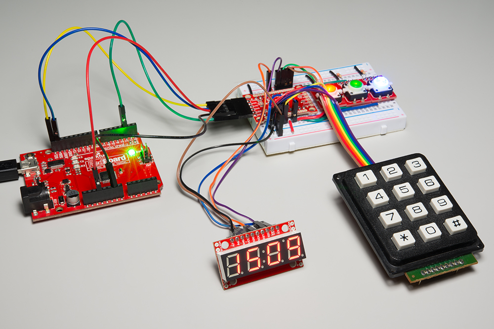
In this example, we'll use seven SX1509 I/O to monitor a 12-button Keypad -- which is a matrix of four rows and three columns. We'll also use the SX1509's interrupt output, so we don't constantly have to poll the I/O expander. Here's the circuit:
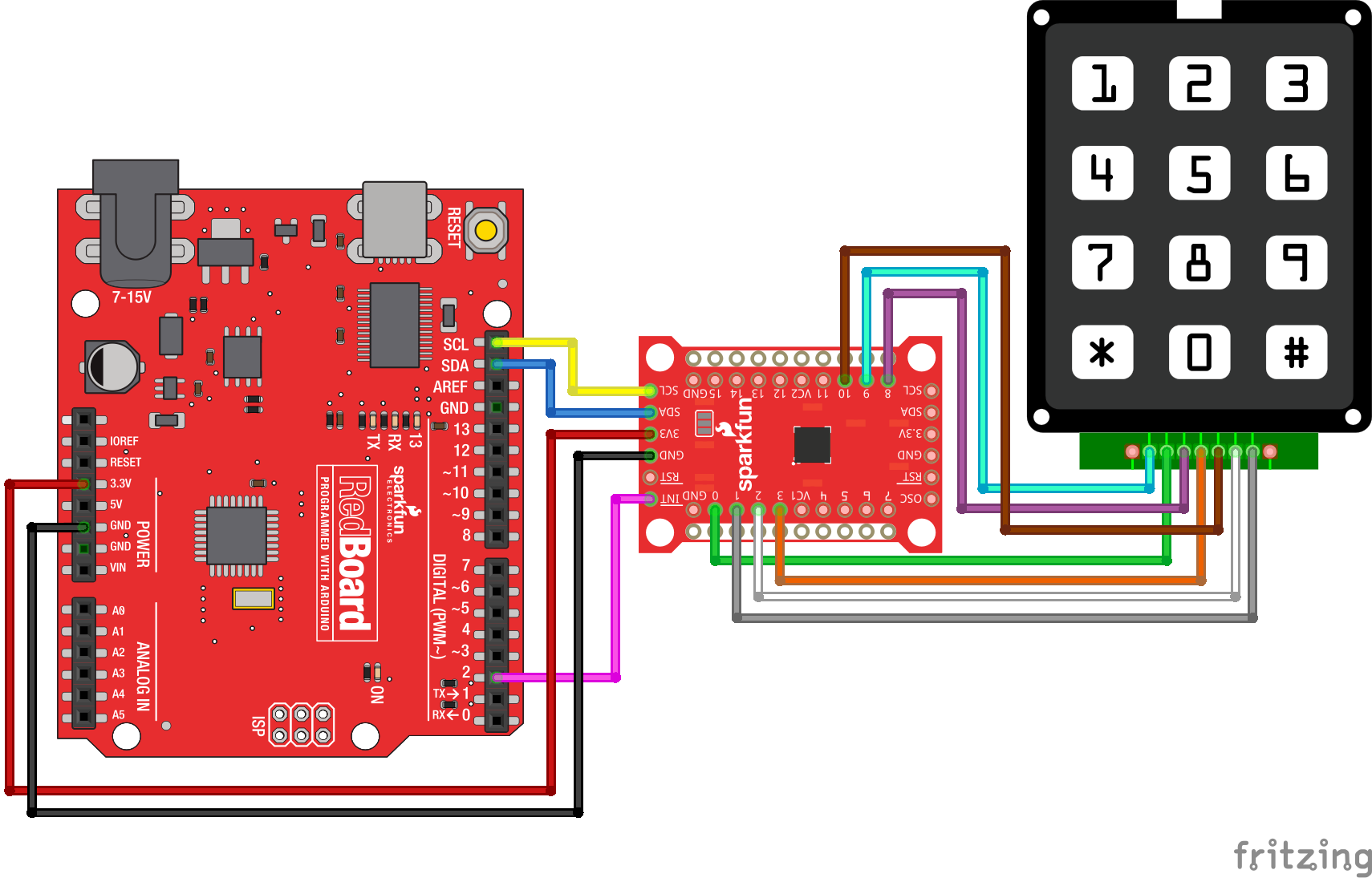
There isn't a lot of flexibility in the SX1509's keypad engine. The rows of you matrix have to be connected, sequentially, to pins 0-7, and the columns wire up to pins 8-15. Our four row buses must route to pins 0-3, and the three columns are connected to 8-10. That still leaves plenty of pins for LED driving!
Here's the example code:
language:c
/*************************************************************
keypadInterrupt.ino
SparkFun SX1509 I/O Expander Example: keypad matrix with int
Jim Lindblom @ SparkFun Electronics
Original Creation Date: September 21, 2015
https://github.com/sparkfun/SparkFun_SX1509_Arduino_Library
This example demonstrates how to use the SX1509's keypad
engine to monitor a matrix of button inputs. The SX1509's
interrupt output is monitored to check for button presses.
For this example, we use the 12-button keypad
(https://www.sparkfun.com/products/8653).
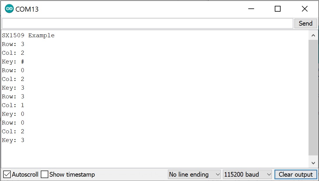
After uploading the sketch, open your serial monitor and
set it to 115200 baud.
Hardware Hookup:
SX1509 Breakout ------ Arduino -------- Keypad Pin
INT --------------- D2
GND -------------- GND
3V3 -------------- 3.3V
SDA ------------ SDA (A4)
SCL ------------ SCL (A5)
0 ---------------------------------- 2 (row 1)
1 ---------------------------------- 7 (row 2)
2 ---------------------------------- 6 (row 3)
3 ---------------------------------- 4 (row 4)
8 ---------------------------------- 3 (col 1)
9 ---------------------------------- 1 (col 2)
10 --------------------------------- 5 (col 3)
Development environment specifics:
IDE: Arduino 1.6.5
Hardware Platform: Arduino Uno
SX1509 Breakout Version: v2.0
This code is beerware; if you see me (or any other SparkFun
employee) at the local, and you've found our code helpful,
please buy us a round!
Distributed as-is; no warranty is given.
*************************************************************/
#include <Wire.h> // Include the I2C library (required)
#include <SparkFunSX1509.h> //Click here for the library: http://librarymanager/All#SparkFun_SX1509
// SX1509 I2C address (set by ADDR1 and ADDR0 (00 by default):
const byte SX1509_ADDRESS = 0x3E; // SX1509 I2C address
SX1509 io; // Create an SX1509 object to be used throughout
#define KEY_ROWS 4 // Number of rows in the keypad matrix
#define KEY_COLS 3 // Number of columns in the keypad matrix
// keyMap maps row/column combinations to characters:
char keyMap[KEY_ROWS][KEY_COLS] = {
{'1', '2', '3'},
{'4', '5', '6'},
{'7', '8', '9'},
{'*', '0', '#'}};
const byte ARDUINO_INTERRUPT_PIN = 2;
void setup()
{
Serial.begin(115200);
Serial.println("SX1509 Example");
Wire.begin();
// Call io.begin(<address>) to initialize the SX1509. If it
// successfully communicates, it'll return 1.
if (io.begin(SX1509_ADDRESS) == false)
{
Serial.println("Failed to communicate. Check wiring and address of SX1509.");
while (1)
; // If we fail to communicate, loop forever.
}
// Scan time range: 1-128 ms, powers of 2
byte scanTime = 8; // Scan time per row, in ms
// Debounce time range: 0.5 - 64 ms (powers of 2)
byte debounceTime = 1; // Debounce time
// Sleep time range: 128 ms - 8192 ms (powers of 2) 0=OFF
byte sleepTime = 0;
// Scan time must be greater than debounce time!
io.keypad(KEY_ROWS, KEY_COLS,
sleepTime, scanTime, debounceTime);
// Set up the Arduino interrupt pin as an input w/
// internal pull-up. (The SX1509 interrupt is active-low.)
pinMode(ARDUINO_INTERRUPT_PIN, INPUT_PULLUP);
}
// Compared to the keypad in keypad.ino, this keypad example
// is a bit more advanced. We'll use these varaibles to check
// if a key is being held down, or has been released. Then we
// can kind of emulate the operation of a computer keyboard.
unsigned int previousKeyData = 0; // Stores last key pressed
unsigned int holdCount, releaseCount = 0; // Count durations
const unsigned int holdCountMax = 15; // Key hold limit
const unsigned int releaseCountMax = 100; // Release limit
void loop()
{
// If the SX1509 INT pin goes low, a keypad button has
// been pressed:
if (digitalRead(ARDUINO_INTERRUPT_PIN) == LOW)
{
// Use io.readKeypad() to get the raw keypad row/column
unsigned int keyData = io.readKeypad();
// Then use io.getRow() and io.getCol() to parse that
// data into row and column values.
byte row = io.getRow(keyData);
byte col = io.getCol(keyData);
// Then plug row and column into keyMap to get which
// key was pressed.
char key = keyMap[row][col];
// If it's a new key pressed
if (keyData != previousKeyData)
{
holdCount = 0; // Reset hold-down count
Serial.println(String(key)); // Print the key
}
else // If the button's beging held down:
{
holdCount++; // Increment holdCount
if (holdCount > holdCountMax) // If it exceeds threshold
Serial.println(key); // Print the key
}
releaseCount = 0; // Clear the releaseCount variable
previousKeyData = keyData; // Update previousKeyData
}
// If no keys have been pressed we'll continuously increment
// releaseCount. Eventually creating a release, once the
// count hits the max.
releaseCount++;
if (releaseCount >= releaseCountMax)
{
releaseCount = 0;
previousKeyData = 0;
}
delay(1); // Gives releaseCountMax a more intuitive unit
}
After uploading the code, open the serial monitor and press some keys!
Now just hook up a cellular shield and go make some prank calls!
Keep in mind any of these SX1509 features can be combined, as long as you don't run out of I/O (then just cascade another expander!). Check out the library's examples for demonstrations of other features -- like the clock output, or input debouncing.
Resources and Going Further
Here are a few SX1509 and SX1509 Breakout-related resources you may find handy, as you begin to build your I/O-expanding project:
- Schematic -- A PDF of the breakout board's schematic.
- Eagle File -- A ZIP of the breakout board's Eagle design files.
- Datasheet (SX1509) -- This datasheet has everything you'll need if you want to mess around with the SX1509's register data, or build the SX1509 into a PCB design of your own.
- Arduino Library -- This is where you'll find the latest version of the SX1509 Arduino library.
- GitHub Repository -- Here's where we host all of the design files for the SX1509 Breakout.
What are you going to build with the SX1509 I/O Expander? Any project that needs 16 or more outputs is bound to be blog-worthy. Let us know what you build with it! If you need any inspiration, here are a few tutorials you may find enlightening:
- Using the Serial 7-Segment Display -- You can bit-bang an SPI interface using the SX1509, and use it to drive this 7-Segment LED. Or! Use the SX1509 to drive a basic 7-Segment display.
- Using the Arduino Pro Mini 3.3V -- The Arduino Pro Mini pairs very well with the SX1059!
- Bubble Display Hookup Guide -- These awesome little bubble displays are ripe for interfacing with the SX1509.