Bubble Display Hookup Guide
This Tutorial is Retired!
This tutorial covers concepts or technologies that are no longer current. It's still here for you to read and enjoy, but may not be as useful as our newest tutorials.
 Joel_E_B
Introduction
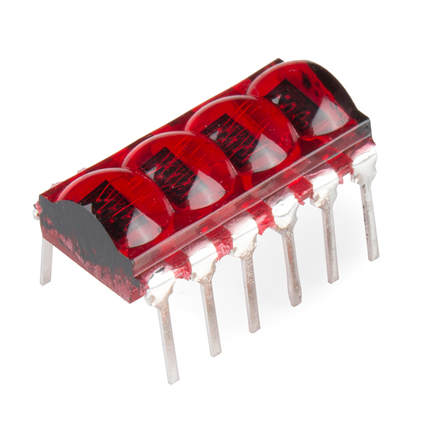
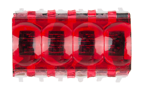
The Bubble Display is a tiny 4-digit, 7-segment display. It's perfect if you need some user feedback from your system, but don't want to fiddle with LCDs or other display options. The Bubble Display comes in an easy-to-use DIP package and can be used in breadboards, protoboards, or PCBs.
Bubble Display - 7-Segment (4-digit)
COM-12710Covered in This Tutorial
This tutorial will go over the basic hardware requirements for the bubble display, show you how to hook one up to an Arduino microcontroller, and then show you a few different example sketches.
Required Materials
To follow along with all of the examples in this tutorial, you will need the following parts:
Suggested Reading
Before you go any further, check the tutorials below, and makes sure you have a good understanding of the concepts mentioned.
Hardware Overview
Let's briefly discuss the characteristics and functionality of the bubble display before we connect it to other hardware.
All the information found on this page and more can be found in the product's datasheet. Consult it, if you need more information.
Power
The bubble display is unique in that, unlike most ICs, these displays don't need a supply voltage. The bubble display is four, 7-segment displays packed into one package, and 7-segment displays are really just seven LEDs lined up in a particular pattern. In this case, the number '8' shape we're all familiar with. Thus, to turn on and off a particular part of the display, you send it a digital HIGH or LOW signal just like you would with a regular LED.
However, you may have noticed that there are more LEDs than there are pins on the IC. There are 32 segments total (counting the decimal points) and only 12 pins. What gives? The answer is that these displays use common-cathode LEDs, which means all the LEDs in a given segment share one ground pin. This is the same method used in RGB LEDs that allows you to control three different colored LEDs with only four pins. With these displays, there are eight pins for the anodes (+) (seven segments and one decimal point per digit) and four pins for the cathode (-) of each digit.
With that said, you still want to limit the amount of current flowing through the LEDs. If you are using a 5V microcontroller such as a SparkFun RedBoard, you'll need to add current limiting resistors to your circuit. Even if you're using a 3.3V micro, you should still add resistors, albeit much smaller values. The following tables from the datasheet give us the information we need to calculate the correct resistor value.

LED calculators, such as this one make it easy to figure out which value resistor to use. For example, if you're using a 5V source to control the segments, you'll want to have a 680 Ω resistor in line with each, assuming that each segment is operating under normal conditions. If you find that the display isn't as bright as you'd like it, you can always add a smaller value resistor. We've found that a 330Ω resistor works well on all four cathode pins.
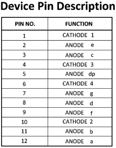
Pinout
Now that we know how to properly provide power to the display, let's go over the segment configuration so we know which pins light up which segments. The pinout for the bubble display is as follows.
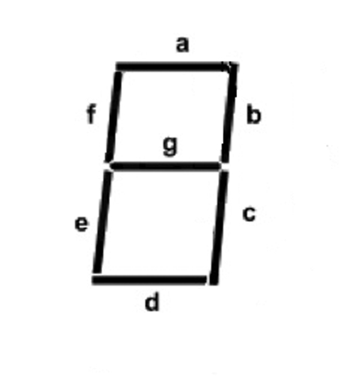
Next, take a look at the segment key.
Last, here is a diagram showing the numbering of the digits as they correspond to the pins labeled above.
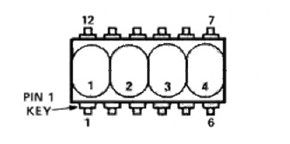
Building from what we discussed above, we can start to make sense of this. For example, let's say we wanted to turn on Segment_A on Digit_1. Looking at the table above we see that Segment_A (labeled Anode a) is pin 12. Looking at the same table, we can also see that the cathode for Digit_1 is pin 1. If you connect pin 1 to GND, and pin 12 to 3.3V or 5V (don't forget that resistor!), you should see the topmost segment on the leftmost digit light up. Yay LEDs! From here you can extrapolate how the rest works. If you wanted to light up Segment_A on both Digit_1 and Digit_4, you would simply add another connection to our first example from GND to pin 6 (cathode 4), and so on...
Lighting up individual segments is fun for about a minute, so let's move on and get this thing displaying some useful information.
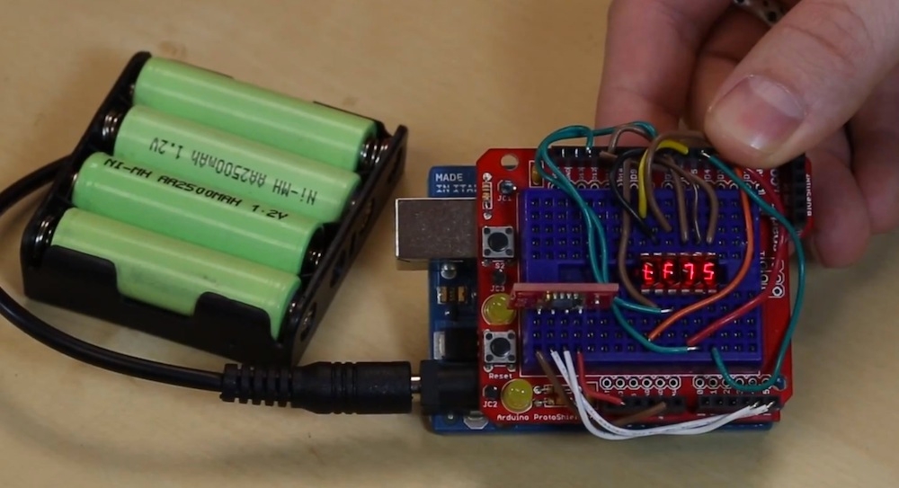
Hooking it Up
In order to talk to the bubble display, we'll need a microcontroller. This example will use a SparkFun RedBoard to control the display, but you can use whichever you choose. You'll also need some jumper wires, some resistors, and a breadboard.
This IC is polarized, so pay attention to which way you stick it in the breadboard! Pin one is indicated by a white dot on the underside of the part.
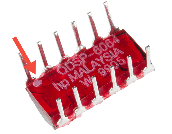
Once you have the bubble display oriented correctly on the breadboard, hook everything up like the image below shows:
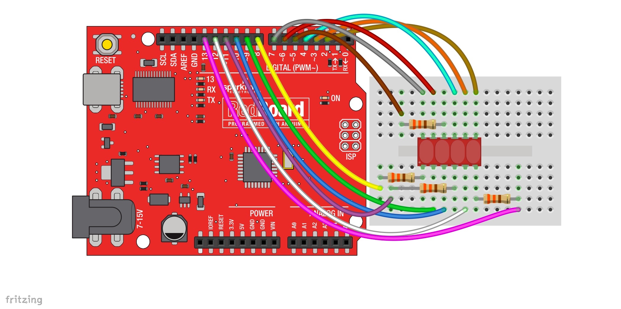
While the display may work without current limiting resistors, it's always a good idea to have them in your circuit to avoid burning out your display. You may also opt to have your resistors on the eight anode pins rather than the four cathode pins. You will need to add a little more hardware, but the result will be a much more balanced brightness in your display no matter which character you're displaying.
Now, it's time to light up the display with some code.
Firmware
Before you can start writing code to control the bubble displays, you'll need to install the SevSeg Arduino Library first. You can download it from the GitHub repo. If you need more details on installing a library, visit our Installing an Arduino Library tutorial, and, if you are unfamiliar with GitHub, there's a tutorial for that too.
Once the library is installed, we can use the included example sketches to get started using the bubble display.
Example 1: Counter
Go to File -> Examples -> SevSeg -> Example -> Bubble_Display_Counter.
Here is the code for those who would like to see it without downloading it.
language:c
/*
 March 6, 2014
 Spark Fun Electronics
 Nathan Seidle
 Updates by Joel Bartlett

 This code is originally based Dean Reading's Library deanreading@hotmail.com
 http://arduino.cc/playground/Main/SevenSegmentLibrary
 He didn't have a license on it so I hope he doesn't mind me making it public domain:
 This code is public domain but you buy me a beer if you use this and we meet someday (Beerware license).

 This sketch provides a simple counter example for the HP Bubble display from SparkFun.
 https://www.sparkfun.com/products/12710

 Pinout for HP Bubble Display:
 1:  Cathode 1
 2:  Anode E
 3:  Anode C
 4:  Cathode 3
 5:  Anode dp
 6:  Cathode 4
 7:  Anode G
 8:  Anode D
 9:  Anode F
 10: Cathode 2
 11: Anode B
 12: Anode A
 */

#include "SevSeg.h"

//Create an instance of the object.
SevSeg myDisplay;

//Create global variables
unsigned long timer;
int deciSecond = 0;

void setup()
{

  int displayType = COMMON_CATHODE; //Your display is either common cathode or common anode


  //This pinout is for a bubble dispaly
   //Declare what pins are connected to the GND pins (cathodes)
   int digit1 = 8; //Pin 1
   int digit2 = 5; //Pin 10
   int digit3 = 11; //Pin 4
   int digit4 = 13; //Pin 6

   //Declare what pins are connected to the segments (anodes)
   int segA = 7; //Pin 12
   int segB = 6; //Pin 11
   int segC = 10; //Pin 3
   int segD = 3; //Pin 8
   int segE = 9; //Pin 2
   int segF = 4; //Pin 9
   int segG = 2; //Pin 7
   int segDP= 12; //Pin 5

  int numberOfDigits = 4; //Do you have a 1, 2 or 4 digit display?

  myDisplay.Begin(displayType, numberOfDigits, digit1, digit2, digit3, digit4, segA, segB, segC, segD, segE, segF, segG, segDP);

  myDisplay.SetBrightness(100); //Set the display to 100% brightness level

  timer = millis();
}

void loop()
{
  //Example ways of displaying a decimal number
  char tempString[10]; //Used for sprintf
  sprintf(tempString, "%4d", deciSecond); //Convert deciSecond into a string that is right adjusted
  //sprintf(tempString, "%d", deciSecond); //Convert deciSecond into a string that is left adjusted
  //sprintf(tempString, "%04d", deciSecond); //Convert deciSecond into a string with leading zeros
  //sprintf(tempString, "%4d", deciSecond * -1); //Shows a negative sign infront of right adjusted number
  //sprintf(tempString, "%4X", deciSecond); //Count in HEX, right adjusted

  //Produce an output on the display
  myDisplay.DisplayString(tempString, 0); //(numberToDisplay, decimal point location)

  //Other examples
  //myDisplay.DisplayString(tempString, 0); //Display string, no decimal point
  //myDisplay.DisplayString("-23b", 3); //Display string, decimal point in third position

  //Check if 10ms has elapsed
  if (millis() - timer >= 100)
  {
    timer = millis();
    deciSecond++;
  }

  delay(5);
}
With this sketch uploaded, the display with count up, with each order of magnitude spilling onto the next digit to the left.
Example 2: Text
The next example shows how to display text. Since these display are 7-segment and not alphanumeric, they are limited in which characters they can and can't display. The sketch has a table listing all there characters and whether or not they can be displayed.
To open this sketch, go to File -> Examples -> SevSeg -> Example -> Bubble_Display_Text.
language:c
/*
 March 6, 2014
 Spark Fun Electronics
 Nathan Seidle
 Updates by Joel Bartlett

 This code is originally based Dean Reading's Library deanreading@hotmail.com
 http://arduino.cc/playground/Main/SevenSegmentLibrary
 He didn't have a license on it so I hope he doesn't mind me making it public domain:
 This code is public domain but you buy me a beer if you use this and we meet someday (Beerware license).

The example shows you how to display characters to the bubble display. Since this is a 7-segment display
and not an alpha-numeric display, there are numerous characters that cannot be displayed. The table below
should give you an idea which ones can.


 Pinout for HP Bubble Display:
 1:  Cathode 1
 2:  Anode E
 3:  Anode C
 4:  Cathode 3
 5:  Anode dp
 6:  Cathode 4
 7:  Anode G
 8:  Anode D
 9:  Anode F
 10: Cathode 2
 11: Anode B
 12: Anode A

 Here is the character map found in the SevSeg.h file for reference
 as to which characters can be displayed and which can't.

 //  ABCDEFG  Segments
  0b1111110, // 0
  0b0110000, // 1
  0b1101101, // 2
  0b1111001, // 3
  0b0110011, // 4
  0b1011011, // 5
  0b1011111, // 6
  0b1110000, // 7
  0b1111111, // 8
  0b1111011, // 9
  0b1110111, // 10  "A"
  0b0011111, // 11  "B"
  0b1001110, // 12  "C"
  0b0111101, // 13  "D"
  0b1001111, // 14  "E"
  0b1000111, // 15  "F"
  0b0000000, // 16  NO DISPLAY
  0b0000000, // 17  NO DISPLAY
  0b0000000, // 18  NO DISPLAY
  0b0000000, // 19  NO DISPLAY
  0b0000000, // 20  NO DISPLAY
  0b0000000, // 21  NO DISPLAY
  0b0000000, // 22  NO DISPLAY
  0b0000000, // 23  NO DISPLAY
  0b0000000, // 24  NO DISPLAY
  0b0000000, // 25  NO DISPLAY
  0b0000000, // 26  NO DISPLAY
  0b0000000, // 27  NO DISPLAY
  0b0000000, // 28  NO DISPLAY
  0b0000000, // 29  NO DISPLAY
  0b0000000, // 30  NO DISPLAY
  0b0000000, // 31  NO DISPLAY
  0b0000000, // 32 ' '
  0b0000000, // 33 '!'  NO DISPLAY
  0b0100010, // 34 '"'
  0b0000000, // 35 '#'  NO DISPLAY
  0b0000000, // 36 '$'  NO DISPLAY
  0b0000000, // 37 '%'  NO DISPLAY
  0b0000000, // 38 '&'  NO DISPLAY
  0b0100000, // 39 '''
  0b1001110, // 40 '('
  0b1111000, // 41 ')'
  0b0000000, // 42 '*'  NO DISPLAY
  0b0000000, // 43 '+'  NO DISPLAY
  0b0000100, // 44 ','
  0b0000001, // 45 '-'
  0b0000000, // 46 '.'  NO DISPLAY
  0b0000000, // 47 '/'  NO DISPLAY
  0b1111110, // 48 '0'
  0b0110000, // 49 '1'
  0b1101101, // 50 '2'
  0b1111001, // 51 '3'
  0b0110011, // 52 '4'
  0b1011011, // 53 '5'
  0b1011111, // 54 '6'
  0b1110000, // 55 '7'
  0b1111111, // 56 '8'
  0b1111011, // 57 '9'
  0b0000000, // 58 ':'  NO DISPLAY
  0b0000000, // 59 ';'  NO DISPLAY
  0b0000000, // 60 '<'  NO DISPLAY
  0b0000000, // 61 '='  NO DISPLAY
  0b0000000, // 62 '>'  NO DISPLAY
  0b0000000, // 63 '?'  NO DISPLAY
  0b0000000, // 64 '@'  NO DISPLAY
  0b1110111, // 65 'A'
  0b0011111, // 66 'B'
  0b1001110, // 67 'C'
  0b0111101, // 68 'D'
  0b1001111, // 69 'E'
  0b1000111, // 70 'F'
  0b1011110, // 71 'G'
  0b0110111, // 72 'H'
  0b0110000, // 73 'I'
  0b0111000, // 74 'J'
  0b0000000, // 75 'K'  NO DISPLAY
  0b0001110, // 76 'L'
  0b0000000, // 77 'M'  NO DISPLAY
  0b0010101, // 78 'N'
  0b1111110, // 79 'O'
  0b1101111, // 80 'P'
  0b1110011, // 81 'Q'
  0b0000101, // 82 'R'
  0b1011011, // 83 'S'
  0b0001111, // 84 'T'
  0b0111110, // 85 'U'
  0b0000000, // 86 'V'  NO DISPLAY
  0b0000000, // 87 'W'  NO DISPLAY
  0b0000000, // 88 'X'  NO DISPLAY
  0b0111011, // 89 'Y'
  0b0000000, // 90 'Z'  NO DISPLAY
  0b1001110, // 91 '['
  0b0000000, // 92 '\'  NO DISPLAY
  0b1111000, // 93 ']'
  0b0000000, // 94 '^'  NO DISPLAY
  0b0001000, // 95 '_'
  0b0000010, // 96 '`'
  0b1110111, // 97 'a' SAME AS CAP
  0b0011111, // 98 'b' SAME AS CAP
  0b0001101, // 99 'c'
  0b0111101, // 100 'd' SAME AS CAP
  0b1101111, // 101 'e'
  0b1000111, // 102 'f' SAME AS CAP
  0b1011110, // 103 'g' SAME AS CAP
  0b0010111, // 104 'h'
  0b0010000, // 105 'i'
  0b0111000, // 106 'j' SAME AS CAP
  0b0000000, // 107 'k'  NO DISPLAY
  0b0110000, // 108 'l'
  0b0000000, // 109 'm'  NO DISPLAY
  0b0010101, // 110 'n' SAME AS CAP
  0b0011101, // 111 'o'
  0b1100111, // 112 'p' SAME AS CAP
  0b1110011, // 113 'q' SAME AS CAP
  0b0000101, // 114 'r' SAME AS CAP
  0b1011011, // 115 's' SAME AS CAP
  0b0001111, // 116 't' SAME AS CAP
  0b0011100, // 117 'u'
  0b0000000, // 118 'b'  NO DISPLAY
  0b0000000, // 119 'w'  NO DISPLAY
  0b0000000, // 120 'x'  NO DISPLAY
  0b0000000, // 121 'y'  NO DISPLAY
  0b0000000, // 122 'z'  NO DISPLAY
  0b0000000, // 123 '0b'  NO DISPLAY
  0b0000000, // 124 '|'  NO DISPLAY
  0b0000000, // 125 ','  NO DISPLAY
  0b0000000, // 126 '~'  NO DISPLAY
  0b0000000, // 127 'DEL'  NO DISPLAY
 */

#include "SevSeg.h"

//Create an instance of the object.
SevSeg myDisplay;

//Create global variables
unsigned long timer;
int deciSecond = 0;

void setup()
{

  int displayType = COMMON_CATHODE; //Your display is either common cathode or common anode


  //This pinout is for a bubble dispaly
   //Declare what pins are connected to the GND pins (cathodes)
   int digit1 = 8; //Pin 1
   int digit2 = 5; //Pin 10
   int digit3 = 11; //Pin 4
   int digit4 = 13; //Pin 6

   //Declare what pins are connected to the segments (anodes)
   int segA = 7; //Pin 12
   int segB = 6; //Pin 11
   int segC = 10; //Pin 3
   int segD = 3; //Pin 8
   int segE = 9; //Pin 2
   int segF = 4; //Pin 9
   int segG = 2; //Pin 7
   int segDP= 12; //Pin 5

  int numberOfDigits = 4; //Do you have a 1, 2 or 4 digit display?

  myDisplay.Begin(displayType, numberOfDigits, digit1, digit2, digit3, digit4, segA, segB, segC, segD, segE, segF, segG, segDP);

  myDisplay.SetBrightness(100); //Set the display to 100% brightness level

  timer = millis();
}

void loop()
{
  char tempString[5] = {'C','O','D','E'}; //Used for sprintf

  for(int i =0;i<100;i++)
  {

  myDisplay.DisplayString(tempString, 0); //(numberToDisplay, decimal point location)

  delay(10);
  }

   for(int i =0;i<100;i++)
  {
      tempString[0] = 58;
      tempString[1] = 'I';
      tempString[2] = 'S';
      tempString[3] = 58;

      myDisplay.DisplayString(tempString, 0);

      delay(10);
  }
   for(int i =0;i<100;i++)
  {
      tempString[0] = 'C';
      tempString[1] = 'O';
      tempString[2] = 'O';
      tempString[3] = 'L';

      myDisplay.DisplayString(tempString, 0);

      delay(10);
  }

}
Example 3: Sensor Data
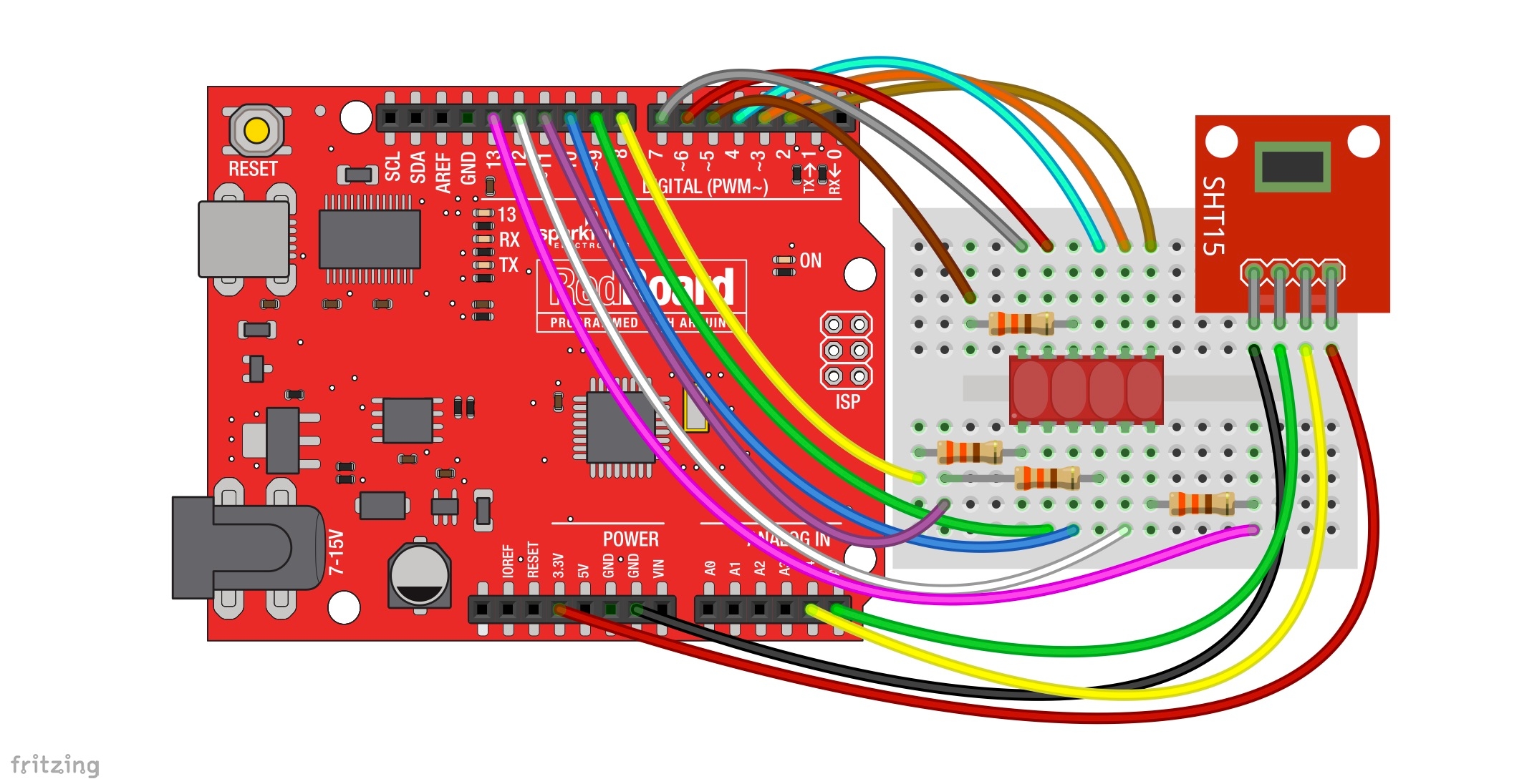
This last example is more of a real-world application. By adding a temperature and humidity sensor to the RedBoard, we can make a tiny, digital thermometer and hygrometer.
First, you need to add a SHT15 to your circuit. You may use whatever sensors you like, but you will need to alter the code accordingly.
Now, go to File -> Examples -> SevSeg -> Example -> Bubble_Display_SHT15 to open up the sketch.
language:c
/*
 March 6, 2014
 Spark Fun Electronics
 Nathan Seidle
 Updates by Joel Bartlett

 This code is originally based Dean Reading's Library deanreading@hotmail.com
 http://arduino.cc/playground/Main/SevenSegmentLibrary
 He didn't have a license on it so I hope he doesn't mind me making it public domain:
 This code is public domain but you buy me a beer if you use this and we meet someday (Beerware license).

This example gives you a real world scenario in which we take sensor data (in this case temperature and humidity
data from a SHT15) and print it to the bubble display using characters and numbers.


 Pinout for HP Bubble Display:
 1:  Cathode 1
 2:  Anode E
 3:  Anode C
 4:  Cathode 3
 5:  Anode dp
 6:  Cathode 4
 7:  Anode G
 8:  Anode D
 9:  Anode F
 10: Cathode 2
 11: Anode B
 12: Anode A

 Pinout for SHT15:
 Vcc: 3.3V
 Data: A4 or SDA on newer Arduino boards
 SCK: A5 or SCK on newer Arduino boards
 GND: GND

 Here is the character map found in the SevSeg.h file for reference
 as to which characters can be displayed and which can't.

 //  ABCDEFG  Segments
  0b1111110, // 0
  0b0110000, // 1
  0b1101101, // 2
  0b1111001, // 3
  0b0110011, // 4
  0b1011011, // 5
  0b1011111, // 6
  0b1110000, // 7
  0b1111111, // 8
  0b1111011, // 9
  0b1110111, // 10  "A"
  0b0011111, // 11  "B"
  0b1001110, // 12  "C"
  0b0111101, // 13  "D"
  0b1001111, // 14  "E"
  0b1000111, // 15  "F"
  0b0000000, // 16  NO DISPLAY
  0b0000000, // 17  NO DISPLAY
  0b0000000, // 18  NO DISPLAY
  0b0000000, // 19  NO DISPLAY
  0b0000000, // 20  NO DISPLAY
  0b0000000, // 21  NO DISPLAY
  0b0000000, // 22  NO DISPLAY
  0b0000000, // 23  NO DISPLAY
  0b0000000, // 24  NO DISPLAY
  0b0000000, // 25  NO DISPLAY
  0b0000000, // 26  NO DISPLAY
  0b0000000, // 27  NO DISPLAY
  0b0000000, // 28  NO DISPLAY
  0b0000000, // 29  NO DISPLAY
  0b0000000, // 30  NO DISPLAY
  0b0000000, // 31  NO DISPLAY
  0b0000000, // 32 ' '
  0b0000000, // 33 '!'  NO DISPLAY
  0b0100010, // 34 '"'
  0b0000000, // 35 '#'  NO DISPLAY
  0b0000000, // 36 '$'  NO DISPLAY
  0b0000000, // 37 '%'  NO DISPLAY
  0b0000000, // 38 '&'  NO DISPLAY
  0b0100000, // 39 '''
  0b1001110, // 40 '('
  0b1111000, // 41 ')'
  0b0000000, // 42 '*'  NO DISPLAY
  0b0000000, // 43 '+'  NO DISPLAY
  0b0000100, // 44 ','
  0b0000001, // 45 '-'
  0b0000000, // 46 '.'  NO DISPLAY
  0b0000000, // 47 '/'  NO DISPLAY
  0b1111110, // 48 '0'
  0b0110000, // 49 '1'
  0b1101101, // 50 '2'
  0b1111001, // 51 '3'
  0b0110011, // 52 '4'
  0b1011011, // 53 '5'
  0b1011111, // 54 '6'
  0b1110000, // 55 '7'
  0b1111111, // 56 '8'
  0b1111011, // 57 '9'
  0b0000000, // 58 ':'  NO DISPLAY
  0b0000000, // 59 ';'  NO DISPLAY
  0b0000000, // 60 '<'  NO DISPLAY
  0b0000000, // 61 '='  NO DISPLAY
  0b0000000, // 62 '>'  NO DISPLAY
  0b0000000, // 63 '?'  NO DISPLAY
  0b0000000, // 64 '@'  NO DISPLAY
  0b1110111, // 65 'A'
  0b0011111, // 66 'B'
  0b1001110, // 67 'C'
  0b0111101, // 68 'D'
  0b1001111, // 69 'E'
  0b1000111, // 70 'F'
  0b1011110, // 71 'G'
  0b0110111, // 72 'H'
  0b0110000, // 73 'I'
  0b0111000, // 74 'J'
  0b0000000, // 75 'K'  NO DISPLAY
  0b0001110, // 76 'L'
  0b0000000, // 77 'M'  NO DISPLAY
  0b0010101, // 78 'N'
  0b1111110, // 79 'O'
  0b1101111, // 80 'P'
  0b1110011, // 81 'Q'
  0b0000101, // 82 'R'
  0b1011011, // 83 'S'
  0b0001111, // 84 'T'
  0b0111110, // 85 'U'
  0b0000000, // 86 'V'  NO DISPLAY
  0b0000000, // 87 'W'  NO DISPLAY
  0b0000000, // 88 'X'  NO DISPLAY
  0b0111011, // 89 'Y'
  0b0000000, // 90 'Z'  NO DISPLAY
  0b1001110, // 91 '['
  0b0000000, // 92 '\'  NO DISPLAY
  0b1111000, // 93 ']'
  0b0000000, // 94 '^'  NO DISPLAY
  0b0001000, // 95 '_'
  0b0000010, // 96 '`'
  0b1110111, // 97 'a' SAME AS CAP
  0b0011111, // 98 'b' SAME AS CAP
  0b0001101, // 99 'c'
  0b0111101, // 100 'd' SAME AS CAP
  0b1101111, // 101 'e'
  0b1000111, // 102 'f' SAME AS CAP
  0b1011110, // 103 'g' SAME AS CAP
  0b0010111, // 104 'h'
  0b0010000, // 105 'i'
  0b0111000, // 106 'j' SAME AS CAP
  0b0000000, // 107 'k'  NO DISPLAY
  0b0110000, // 108 'l'
  0b0000000, // 109 'm'  NO DISPLAY
  0b0010101, // 110 'n' SAME AS CAP
  0b0011101, // 111 'o'
  0b1100111, // 112 'p' SAME AS CAP
  0b1110011, // 113 'q' SAME AS CAP
  0b0000101, // 114 'r' SAME AS CAP
  0b1011011, // 115 's' SAME AS CAP
  0b0001111, // 116 't' SAME AS CAP
  0b0011100, // 117 'u'
  0b0000000, // 118 'b'  NO DISPLAY
  0b0000000, // 119 'w'  NO DISPLAY
  0b0000000, // 120 'x'  NO DISPLAY
  0b0000000, // 121 'y'  NO DISPLAY
  0b0000000, // 122 'z'  NO DISPLAY
  0b0000000, // 123 '0b'  NO DISPLAY
  0b0000000, // 124 '|'  NO DISPLAY
  0b0000000, // 125 ','  NO DISPLAY
  0b0000000, // 126 '~'  NO DISPLAY
  0b0000000, // 127 'DEL'  NO DISPLAY

  SHT15 code based on the code found at Wiring.org
  http://wiring.org.co/learning/basics/humiditytemperaturesht15.html

 */


#include "SevSeg.h"

//Create an instance of the object.
SevSeg myDisplay;

int temperatureCommand  = B00000011;  // command used to read temperature
int humidityCommand = B00000101;  // command used to read humidity

int clockPin = A5;  // pin used for clock
int dataPin  = A4;  // pin used for data
int ack;  // track acknowledgment for errors
int val;
float tempF;
float humidity;
float tempC;

char tempString[5];
//-------------------------------------------------------------------------------------------
void setup()
{
 int displayType = COMMON_CATHODE; //Your display is either common cathode or common anode

//This pinout is for a bubble dispaly
   //Declare what pins are connected to the GND pins (cathodes)
   int digit1 = 8; //Pin 1
   int digit2 = 5; //Pin 10
   int digit3 = 11; //Pin 4
   int digit4 = 13; //Pin 6

   //Declare what pins are connected to the segments (anodes)
   int segA = 7; //Pin 12
   int segB = 6; //Pin 11
   int segC = 10; //Pin 3
   int segD = 3; //Pin 8
   int segE = 9; //Pin 2
   int segF = 4; //Pin 9
   int segG = 2; //Pin 7
   int segDP= 12; //Pin 5

  int numberOfDigits = 4; //Do you have a 1, 2 or 4 digit display?

  myDisplay.Begin(displayType, numberOfDigits, digit1, digit2, digit3, digit4, segA, segB, segC, segD, segE, segF, segG, segDP);

  myDisplay.SetBrightness(100); //Set the display to 100% brightness level
}
//-------------------------------------------------------------------------------------------
void loop()
{

  sht15();
  clear();
  for(int i =0;i<500;i++)
  {
      tempString[0] = 'T';
      tempString[1] = 'F';

      myDisplay.DisplayString(tempString, 0);

    sprintf(tempString, "%4d",  (long)tempF, DEC);
    myDisplay.DisplayString(tempString, 0);
  }
  clear();
   for(int i =0;i<500;i++)
  {
      tempString[0] = 'R';
      tempString[1] = 'H';

    myDisplay.DisplayString(tempString, 0);

    sprintf(tempString, "%4d",  (long)humidity, DEC);
    myDisplay.DisplayString(tempString, 0);
  }
}
//-------------------------------------------------------------------------------------------
void clear()
{
      //write a non-displayable character to each position to clear the display
      tempString[0] = 'm';
      tempString[1] = 'm';
      tempString[2] = 'm';
      tempString[3] = 'm';

      myDisplay.DisplayString(tempString, 0);
}
//-------------------------------------------------------------------------------------------
int sht15()
{
  // read the temperature and convert it to centigrades
  sendCommandSHT(temperatureCommand, dataPin, clockPin);
  waitForResultSHT(dataPin);
  val = getData16SHT(dataPin, clockPin);
  skipCrcSHT(dataPin, clockPin);
  tempC = (float)val * 0.01 - 40;
  tempF = (float)tempC * 1.8 + 32;

  //Serial.print("Temperature: ");
  //Serial.print((long)tempF, DEC);
  //Serial.print("_");
  //Serial.print((char)176);
  //Serial.print("F ");

  // read the humidity
  sendCommandSHT(humidityCommand, dataPin, clockPin);
  waitForResultSHT(dataPin);
  val = getData16SHT(dataPin, clockPin);
  skipCrcSHT(dataPin, clockPin);
  humidity = -4.0 + 0.0405 * val + -0.0000028 * val * val;

  //Serial.print(" Relative Humidity: ");
  //Serial.print((long)humidity, DEC);
   //Serial.println("%");
  //delay(1000); // wait for 3 sec for next reading
  return tempF, tempC, humidity;
}


// commands for reading/sending data to a SHTx sensor

int shiftIn(int dataPin, int clockPin, int numBits) {
  int ret = 0;

  for (int i=0; i<numBits; ++i) {
    digitalWrite(clockPin, HIGH);
    //delay(10); not needed :)
    ret = ret*2 + digitalRead(dataPin);
    digitalWrite(clockPin, LOW);
  }
  return(ret);
}

// send a command to the SHTx sensor
void sendCommandSHT(int command, int dataPin, int clockPin) {
  int ack;

  // transmission start
  pinMode(dataPin, OUTPUT);
  pinMode(clockPin, OUTPUT);
  digitalWrite(dataPin, HIGH);
  digitalWrite(clockPin, HIGH);
  digitalWrite(dataPin, LOW);
  digitalWrite(clockPin, LOW);
  digitalWrite(clockPin, HIGH);
  digitalWrite(dataPin, HIGH);
  digitalWrite(clockPin, LOW);

  // shift out the command (the 3 MSB are address and must be 000, the last 5 bits are the command)
  shiftOut(dataPin, clockPin, MSBFIRST, command);

  // verify we get the right ACK
  digitalWrite(clockPin, HIGH);
  pinMode(dataPin, INPUT);
  ack = digitalRead(dataPin);
  if (ack != LOW)
    Serial.println("ACK error 0");
  digitalWrite(clockPin, LOW);
  ack = digitalRead(dataPin);
  if (ack != HIGH)
    Serial.println("ACK error 1");
}

// wait for the SHTx answer
void waitForResultSHT(int dataPin) {
  int ack;

  pinMode(dataPin, INPUT);
  for(int i=0; i<100; ++i) {
    delay(10);
    ack = digitalRead(dataPin);
    if (ack == LOW)
      break;
  }
  if (ack == HIGH)
    Serial.println("ACK error 2");
}

// get data from the SHTx sensor
int getData16SHT(int dataPin, int clockPin) {
  int val;

  // get the MSB (most significant bits)
  pinMode(dataPin, INPUT);
  pinMode(clockPin, OUTPUT);
  val = shiftIn(dataPin, clockPin, 8);
  val *= 256; // this is equivalent to val << 8;

  // send the required ACK
  pinMode(dataPin, OUTPUT);
  digitalWrite(dataPin, HIGH);
  digitalWrite(dataPin, LOW);
  digitalWrite(clockPin, HIGH);
  digitalWrite(clockPin, LOW);

  // get the LSB (less significant bits)
  pinMode(dataPin, INPUT);
  val |= shiftIn(dataPin, clockPin, 8);
  return val;
}

// skip CRC data from the SHTx sensor
void skipCrcSHT(int dataPin, int clockPin) {
  pinMode(dataPin, OUTPUT);
  pinMode(clockPin, OUTPUT);
  digitalWrite(dataPin, HIGH);
  digitalWrite(clockPin, HIGH);
  digitalWrite(clockPin, LOW);
}
//-------------------------------------------------------------------------------------------
When you run the sketch, it should start off by printing tF followed by the temperature in fahrenheit. After ten seconds, it should display rH folowed by the current relative humidity. After ten more seconds, the cycle will repeat.
Resources and Going Further
For more information on the bubble display, check out the resources below:
For more great tutorials and 7-segment displays and LCDs, check out these other offerings from SparkFun Electronics: