Resistors
 jimblom
Example Applications
Resistors exist in just about every electronic circuit ever. Here are a few examples of circuits, which heavily depend on our resistor friends.
LED Current Limiting
Resistors are key in making sure LEDs don't blow up when power is applied. By connecting a resistor in series with an LED, current flowing through the two components can be limited to a safe value.
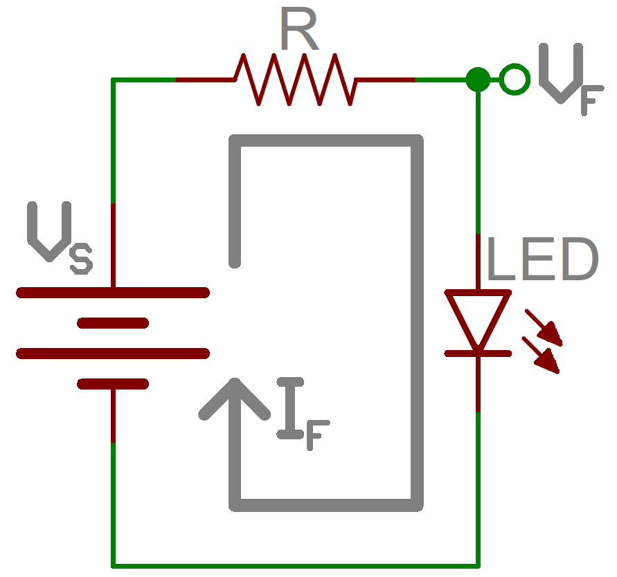
When sizing out a current-limiting resistor, look for two characteristic values of the LED: the typical forward voltage, and the maximum forward current. The typical forward voltage is the voltage which is required to make an LED light up, and it varies (usually somewhere between 1.7V and 3.4V) depending upon the color of the LED. The maximum forward current is usually around 20mA for basic LEDs; continuous current through the LED should always be equal to or less than that current rating.
Once you've gotten ahold of those two values, you can size up a current-limiting resistor with this equation:
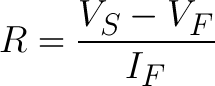
VS is the source voltage -- usually a battery or power supply voltage. VF and IF are the LED's forward voltage and the desired current that runs through it.
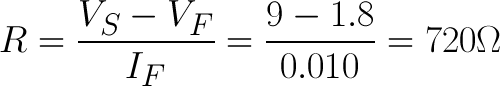
For example, assume you have a 9V battery to power an LED. If your LED is red, it might have a forward voltage around 1.8V. If you want to limit the current to 10mA, use a series resistor of about 720Ω.
Voltage Dividers
A voltage divider is a resistor circuit which turns a large voltage into a smaller one. Using just two resistors in series, an output voltage can be created that's a fraction of the input voltage.
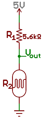
Here's the voltage divider circuit:
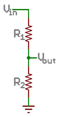
Two resistors, R1 and R2, are connected in series and a voltage source (Vin) is connected across them. The voltage from Vout to GND can be calculated as:
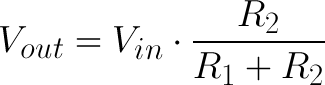
For example, if R1 was 1.7kΩ and R2 was 3.3kΩ, a 5V input voltage could be turned into 3.3V at the Vout terminal.
Voltage dividers are very handy for reading resistive sensors, like photocells, flex sensors, and force-sensitive resistors. One half of the voltage divider is the sensor, and the part is a static resistor. The output voltage between the two components is connected to an analog-to-digital converter on a microcontroller (MCU) to read the sensor's value.
Pull-up Resistors
A pull-up resistor is used when you need to bias a microcontroller's input pin to a known state. One end of the resistor is connected to the MCU's pin, and the other end is connected to a high voltage (usually 5V or 3.3V).
Without a pull-up resistor, inputs on the MCU could be left floating. There's no guarantee that a floating pin is either high (5V) or low (0V).
Pull-up resistors are often used when interfacing with a button or switch input. The pull-up resistor can bias the input-pin when the switch is open. And it will protect the circuit from a short when the switch is closed.
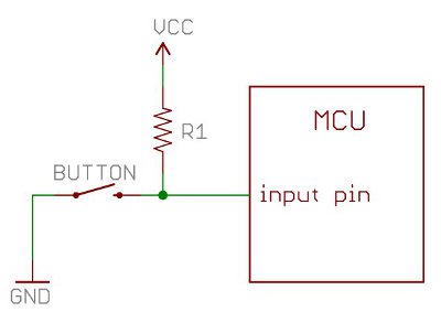
In the circuit above, when the switch is open the MCU's input pin is connected through the resistor to 5V. When the switch closes, the input pin is connected directly to GND.
The value of a pull-up resistor doesn't usually need to be anything specific. But it should be high enough that not too much power is lost if 5V or so is applied across it. Usually values around 10kΩ work well.