Basic Autonomous Kit for Sphero RVR Assembly Guide
 Pearce, Ell C
 Introduction
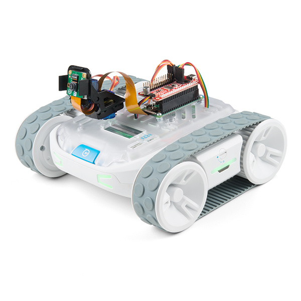
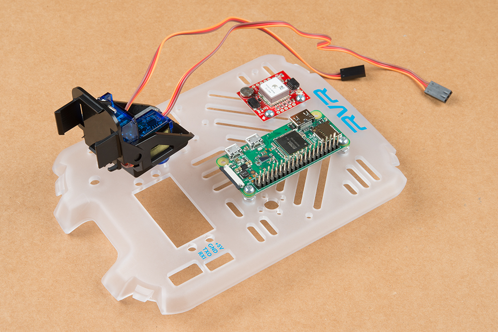
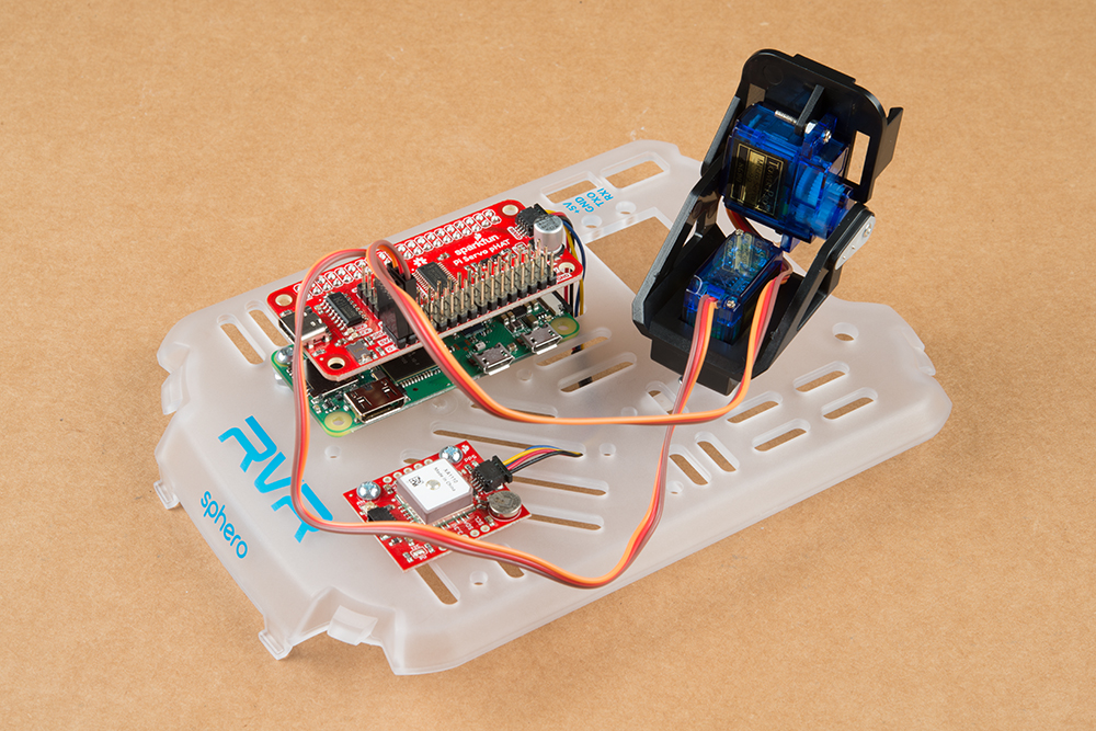
The SparkFun Basic Autonomous Kit for Sphero RVR is an expansion set of sensors to the Sphero RVR platform and is a great way to start driving the Sphero RVR, either remotely or autonomously. The pan-tilt camera provides an excellent base for a video streaming interface while the GPS module provides accurate data for navigation. The Raspberry Pi Zero runs your programming and passes the information to the RVR. Setup is fairly simple but there are a few confusing spots. This tutorial will go over how to properly assemble the kit on the mounting plate provided with the RVR. While we feel it's the best way to set this up, it's not necessarily the only way, so feel free to experiment with different configurations.
Required Materials
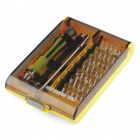
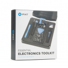
To follow along with this tutorial, you will really only need a phillips-head screwdriver. We have quite a few to choose from - but our Pocket Screwdriver Set is a great option.

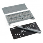
Electric Hobby Screwdriver Set
TOL-15548Before We Begin
If you haven't already, start charging the RVR battery. It takes a while to charge, so now would be a good time to get it going.
Pan Tilt Mechanism
Assembling the pan-tilt rig is by far the most involved part of this tutorial. Take your time and read the instructions carefully. Be mindful of the materials you are working with as well - using too much torque or force when tightening screws or fitting parts together can result in broken parts. On a final note, take extra care to make sure the servos are aligned correctly when mounting them.
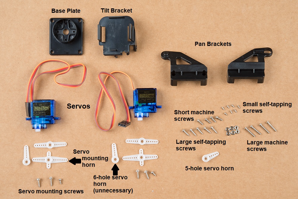
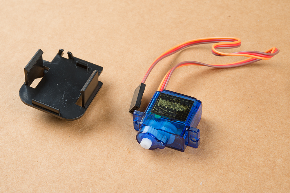
Here are the parts of the pan-tilt rig that come in this kit. You won't be needing the servo horns that come packaged with the servo motors, just the ones that come packaged separately. You will also not need the base plate that comes with the pan-tilt framework package.
First, identify the larger self-tapping screws. These will be used for assembling the bottom part of the mechanism or the "Pan" part.
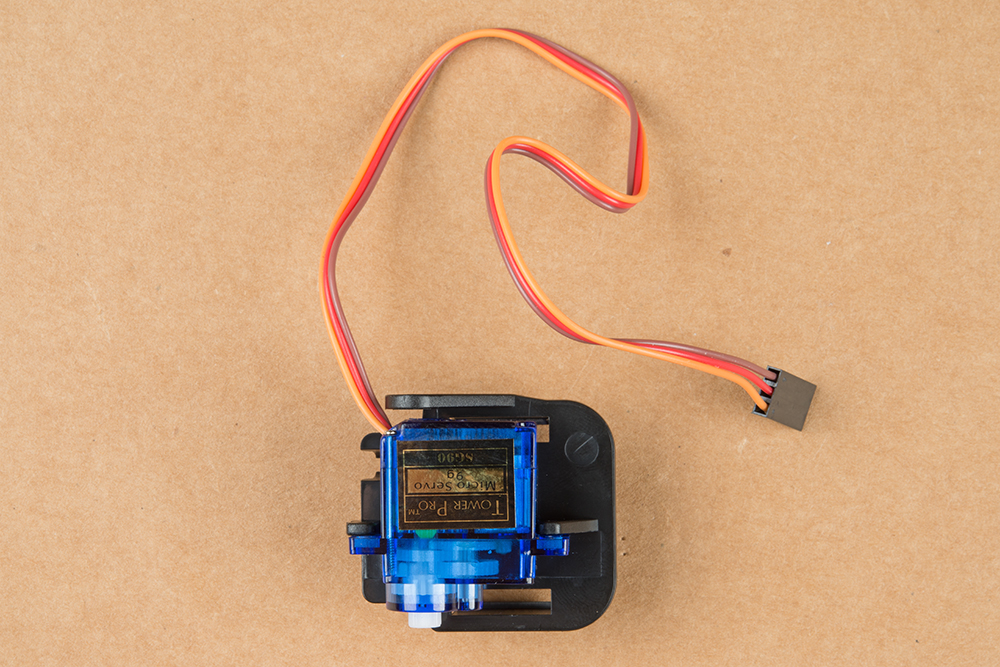
Find the Pan Brackets - these are the two brackets that sandwich together. Place one of the servos in the center and connect the two brackets. Take note of the orientation of the servo in the brackets below as it's important.
Here are the brackets together. Try to make sure the servo is centered.
Take the larger self-tapping screws and affix the two brackets together like in the image below. Take extra care not to over-torque the screws and damage the plastic.

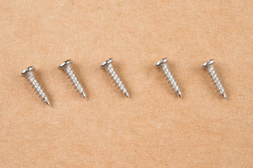
You'll now need the single arm servo horn with 5 holes, as shown in the image below. If, for some reason, the single arm servo with 5 holes was not included in the kit, you have two options. You can either contact Customer Service to have them send you a part, or you can modify one of the 6-hole servo horns that were packaged separately. If you are shortening the 6 hole horn, start by clipping off one hole and checking to see if it fits the mold on the tilt bracket. Be careful when clipping and make sure that you do not clip off too much of the horn.
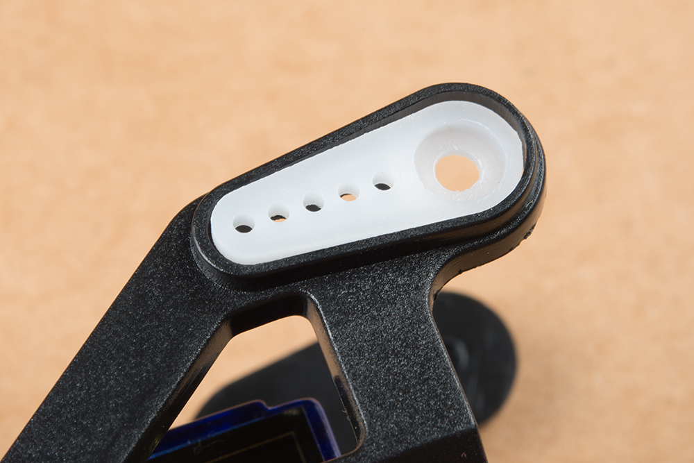
Install the single arm servo horn as shown below. You'll need two of the small self-tapping screws to affix it to the mechanism.
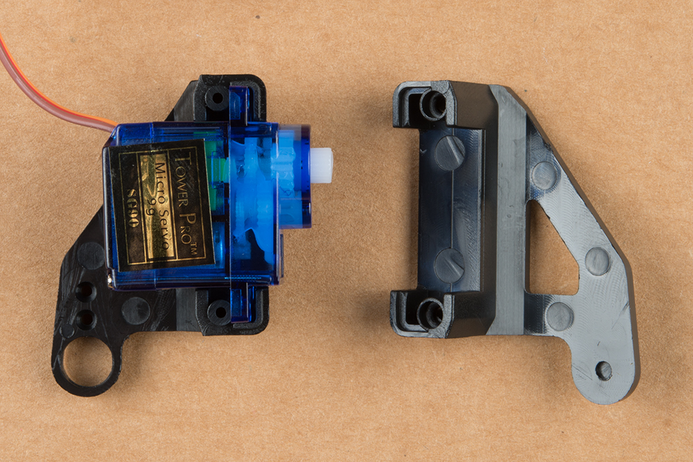
Next, you'll need the second servo motor and the Tilt Bracket.
The image below shows the relative orientation of these two pieces:
Now, find the longest machine screws in the bag, as shown below. You may find that there are more of these than you need.
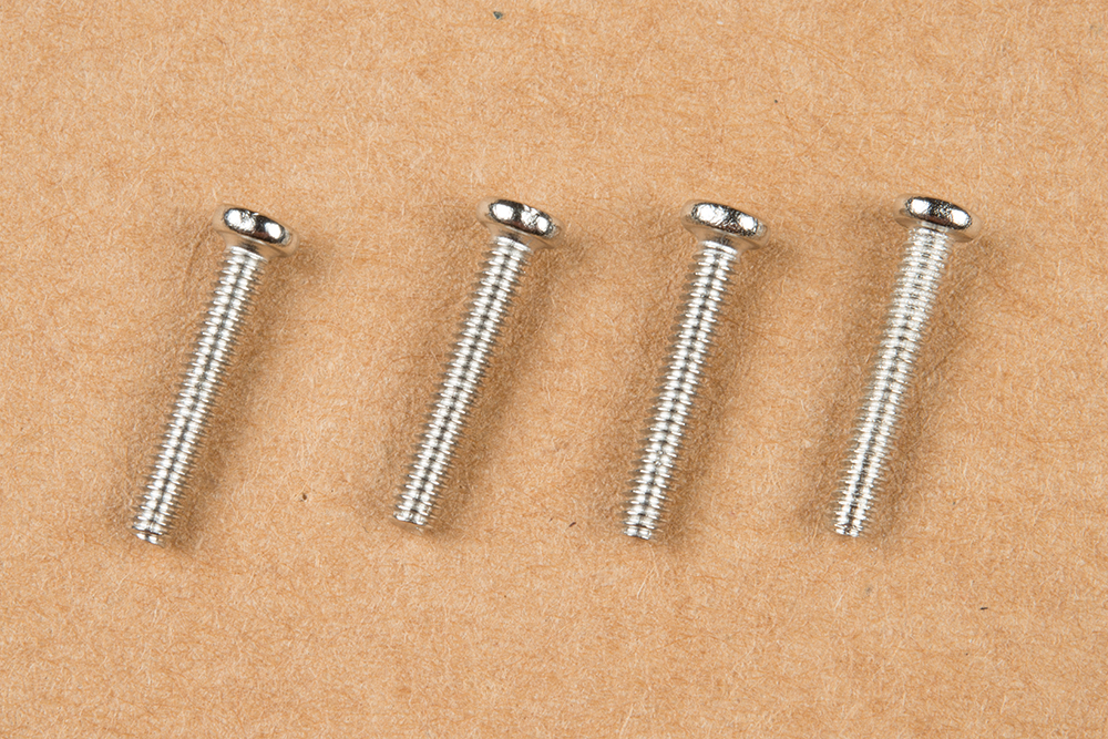
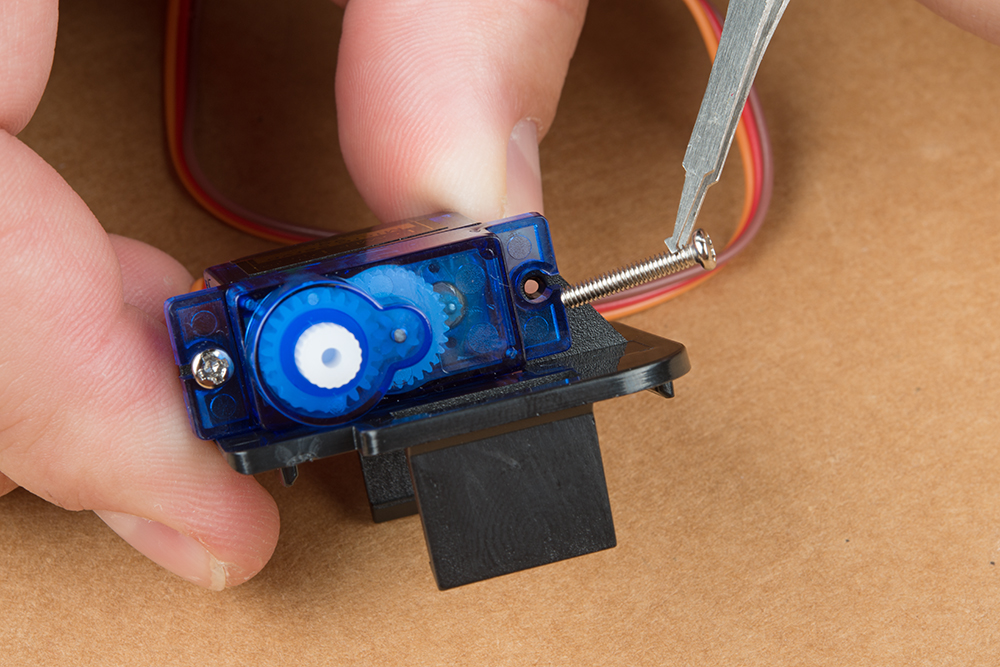
Thread these screws through the stand off wings on the servo motor and into the last piece of the mechanism. You can use nuts for these if you like, but I've found it to be unnecessary as they thread into the mechanism quite snugly without the nut.
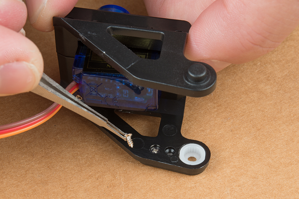
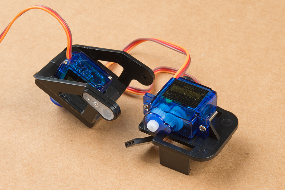
Now connect the two major pieces of the assembly together. The image below shows the orientation of these two parts. You may need to assemble and disassemble these two parts a couple of times to find the right rotational position of the servo motor so that the tilting portion has its full range of motion. Do this by connecting the two parts and carefully turning the "Tilt" servo back and forth until it's able to get the most unobstructed range while the mid-point of this range falls when the two servos are perpendicular to each other.
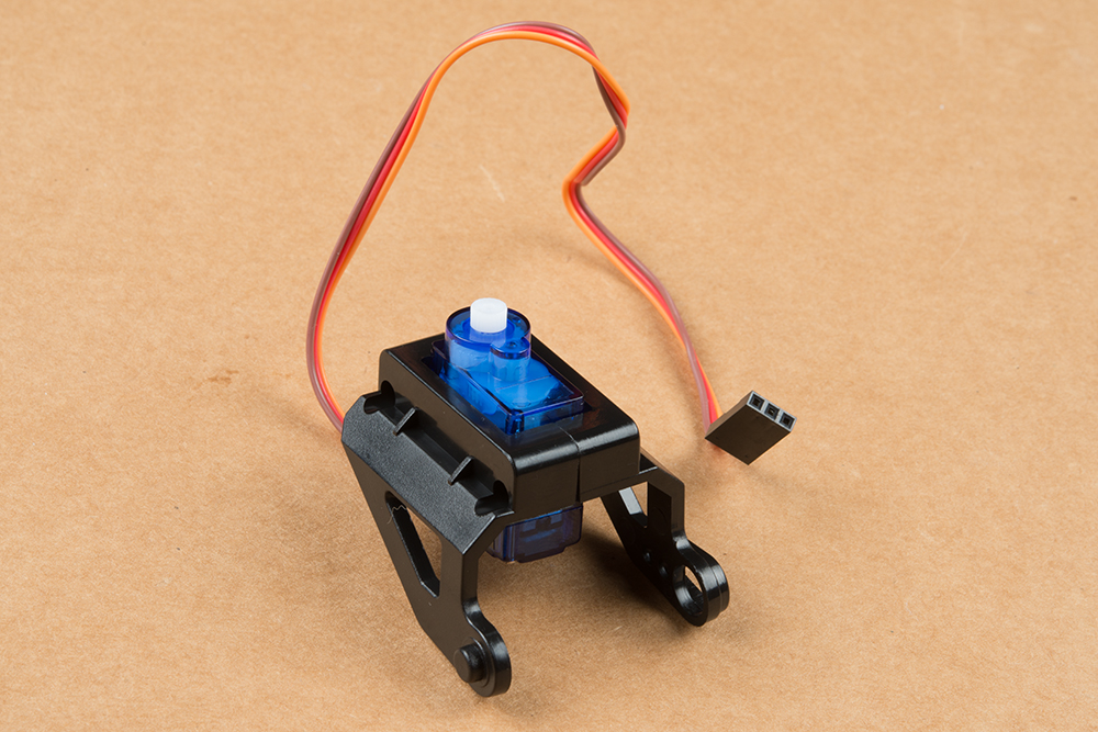
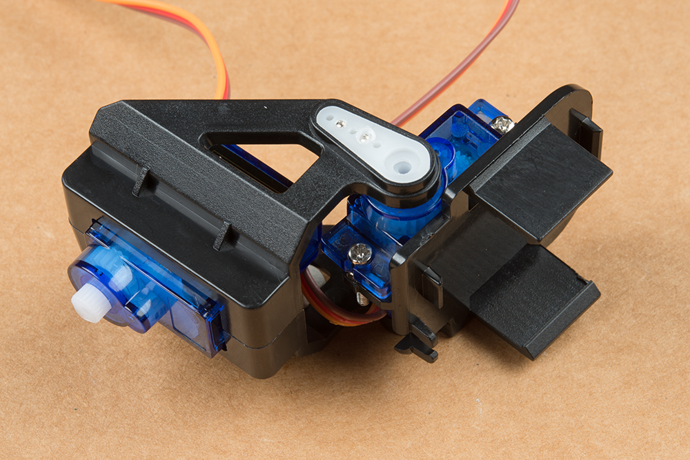
Here's an image of what it should look like with the two mechanisms attached.
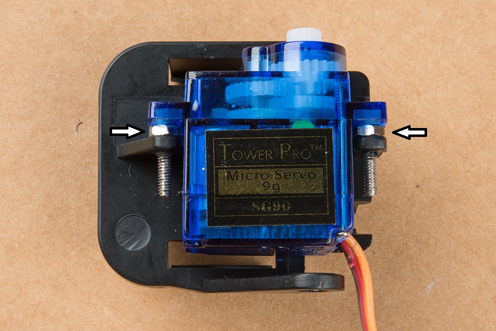
Sometimes the pan and tilt parts won't line up evenly. if this is the case, add a nut (provided in the bag) between the servo and the plastic part of the tilt mechanism as shown below.
Take the final screw that you identified above as a horn attaching screw and use it to secure the horn to the servo motor. You do NOT need much torque here - be very gentle!

Congratulations! You've finished the most difficult part of this build. The rest should be a breeze! Put the pan-tilt mechanism to the side, we'll connect it to the cover plate of the RVR at a later time in the build.
Standoffs and Mounting for the Pi Zero
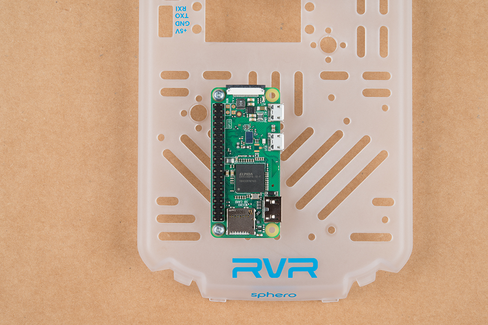
The Pi Zero W mounts to the cover plate with two 4-40 nuts. It uses two of the holes made for the full Raspberry Pi footprint.
This keeps the camera connector within reach of the pan-tilt rig, yet not in a position to tangle itself.
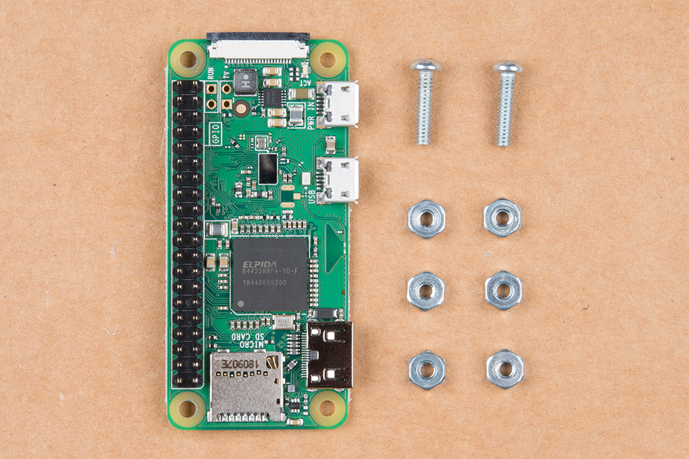
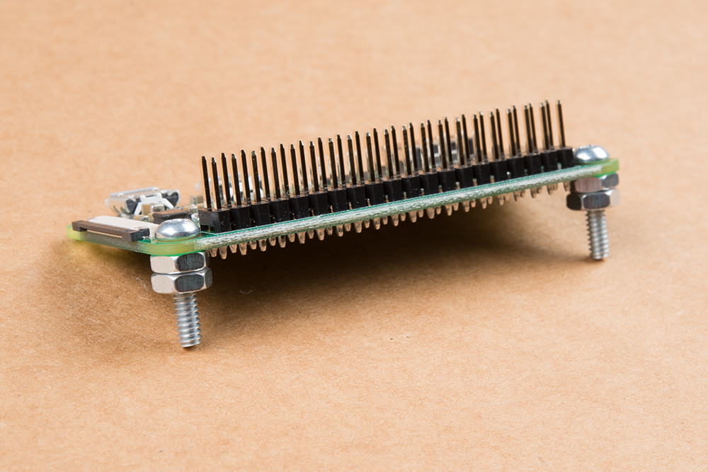
First, we'll affix the 1/2 inch screws to the Raspberry Pi Zero with two 4-40 nuts. This will provide a small standoff from the RVR cover plate which allows room for the pins on the bottom side of the Raspberry Pi Zero.
From there, we'll affix the Pi Zero to the RVR cover plate with a second set of nuts.
Mounting the GPS Board
The GPS Qwiic board mounts next to the Pi Zero W. For the Qwiic cable to work, the Qwiic connectors need to be facing front and back in relation to the RVR. We'll use 2 of the 1/4 inch screws and 2 of the 4-40 nuts.

Mounting Pan - Tilt Camera to the Cover Plate
The pan-tilt rig will mount to the forward-most servo footprint on the cover plate.
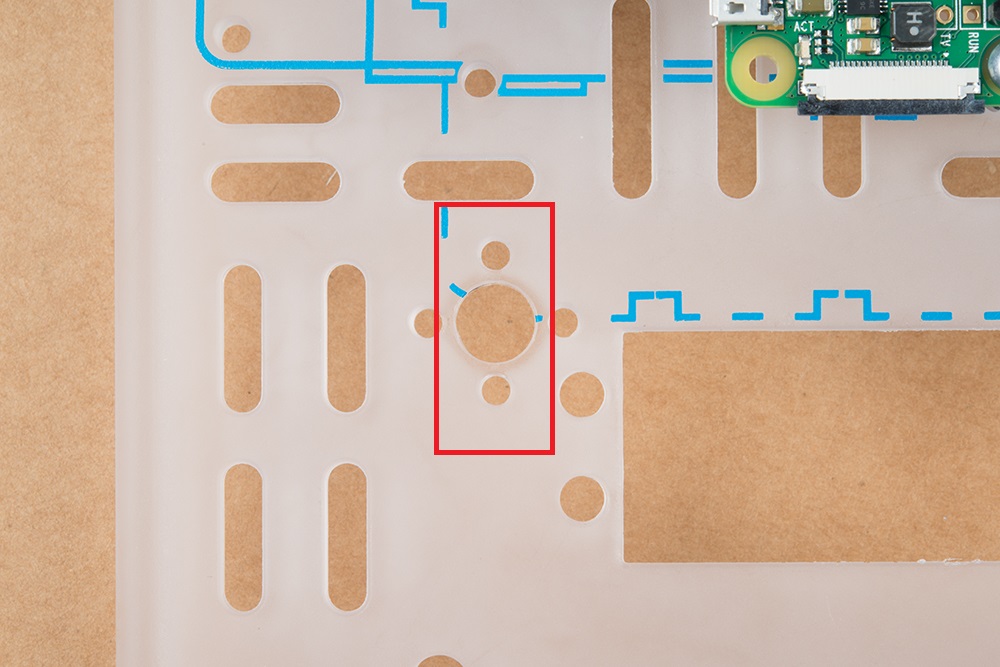
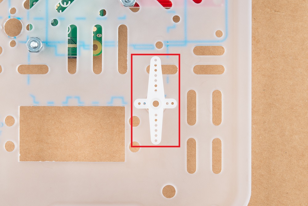
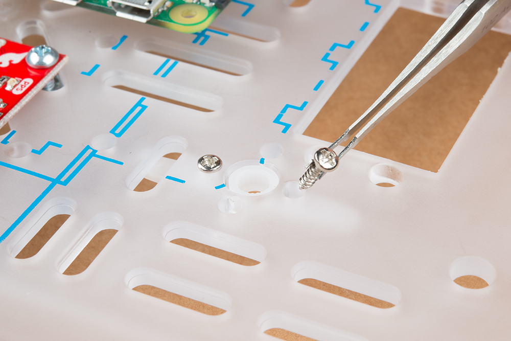
The horn goes under the cover plate. Use two of the self-tapping screws included with the horn to mount the horn to the plate from the top (see pictures below) using the holes that line up.
It’s important that the rig is mounted so that the middle of the servo travel faces forward. This will take some trial and error, but you want the servo to be able to move an equal amount in either direction when facing directly forward (it’s okay to move the servo when it isn’t powered, just don’t force it).
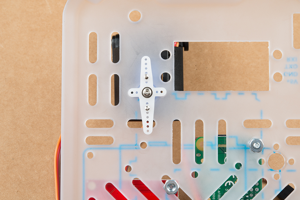
When mounted, it should look similar to this.
Plugging in the pHAT and Cables
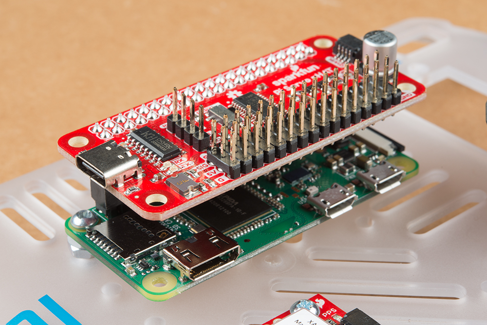
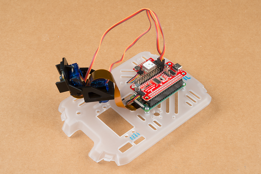
The Servo pHAT is the interface for both the pan-tilt rig and the Qwiic sensors. The pHAT plugs in so it’s stacked directly above the Pi Zero.
The Qwiic cable that connects the GPS Board to the Servo HAT runs underneath the cover plate as shown below. It’s best to plug this in at this step as the pan-tilt cables will impede it later.
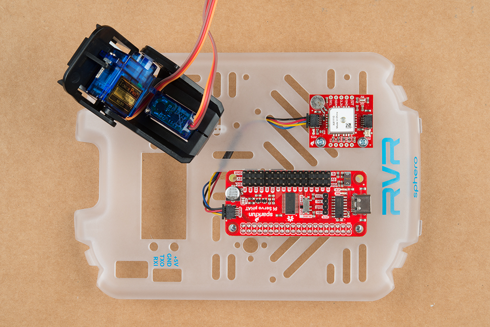
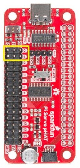
The servo cables for the pan-tilt rig will run underneath the mounting plate, under the board and pop out on the opposite side. The bottom servo plugs into ROW 0 and the top servo into ROW 1.
The brown wires should be on the pins closest to GPS board. See the image below:
You can also run these cables underneath the cover plate but be sure it won't impede the movement of the pan-tilt mechanism.
Plugging in the Camera
You'll need to mount the Raspberry Pi Camera to the pan-tilt mechanism using the included square of double sided tape. However, I recommend you plug in the camera to the ribbon cable before securing the camera to the tape square.
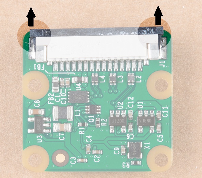
To connect the ribbon cable, you'll need to carefully slide the flexible ribbon cable connector's locking tab out. The locking tab slides out parallel to the board so you'll need to push each side of the tab with your fingernails. The image below highlights where you would need to place your fingernails to slide the tab out.
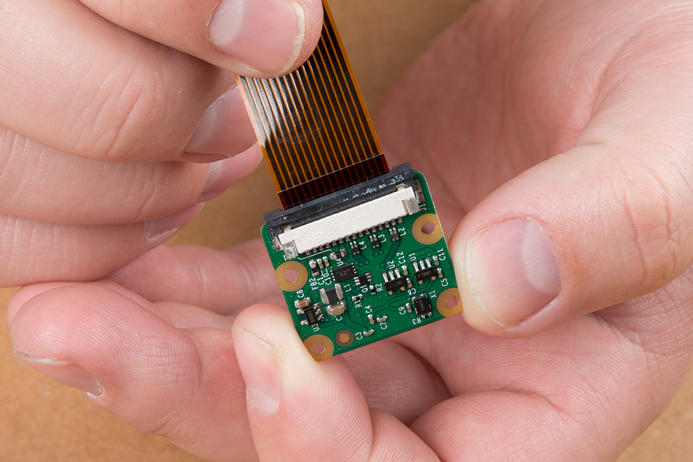
Once the locking tab is out, you can insert the camera connector into the slot. Face the camera's exposed contacts toward the PCB in order to make a connection with the connector's pins. Then insert the cable until it is firmly into the connector. Care must be taken to ensure that the ribbon cable does not have any sharp bends when installing the camera.
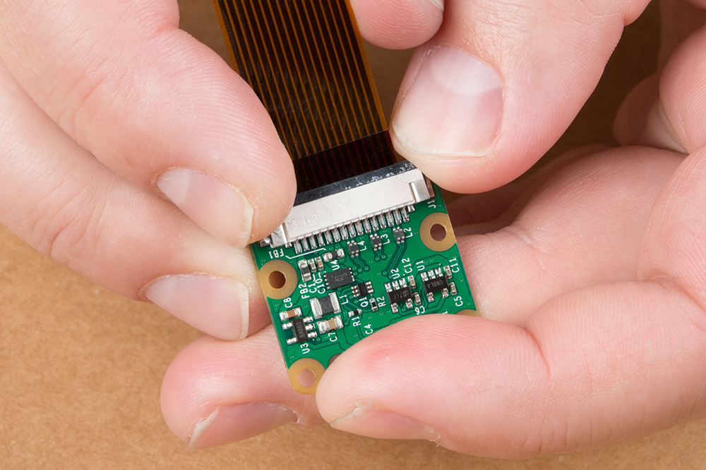
When ready, carefully slide the tab back into the locking position using your fingernails.
Now you can mount the Raspberry Pi Camera to the pan-tilt mechanism. Make sure the correct side is facing up. Once mounted, it should look something like what we see here:

You'll also need to connect the camera ribbon cable to the Pi Zero W. The locking mechanism for the cable is exactly the same as the one on the camera breakout. Again, make sure the contacts of the ribbon are faced correctly. This part can be tricky - take your time and make sure there are no sharp bends in the cable.
Plugging the System into the RVR
You've built the entire system! Now it's time to connect it to the RVR. Gently clip the RVR Cover Plate into place. We'll then connect the 4 pin Ribbon Cable from the four pin connector on the Servo pHAT to the UART Connector on the RVR.
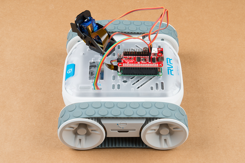
Congratulations! You've completed the kit and are ready to start coding!
Troubleshooting
If your product is not working as you expected or you need technical assistance or information, head on over to the SparkFun Technical Assistance page for some initial troubleshooting.
If you don't find what you need there, the SparkFun Forums are a great place to find and ask for help. If this is your first visit, you'll need to create a Forum Account to search product forums and post questions.
Resources and Going Further
So you've got this amazing looking robot. Now what? Time to program it! Head on over to the Getting Started with the Autonomous Kit for the Sphero RVR Tutorial to get coding.
Getting Started with the Autonomous Kit for the Sphero RVR
Need more information on the components included in this kit? We've got it!
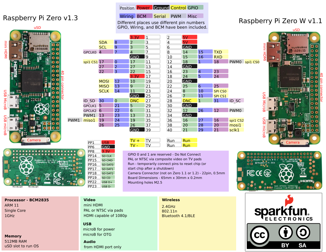
- Raspberry Pi Zero:
- Pi Servo Hat:
- Raspberry Pi Camera Module V2:
- GPS Breakout XA1110 (Qwiic):
Need more inspiration? Check out some of these other great SparkFun tutorials!