SparkFun 5V/1A LiPo Charger/Booster Hookup Guide
 MTaylor
 Introduction
The SparkFun 5V/1A LiPo Charger/Booster is a no nonsense circuit for generating an amp from a lipo, at 5 volts. It's low cost, has a simple booster circuit realizing the PAM2401 IC, and includes protection diodes so you can run multiple cells in series for extra kick. When a booster circuit is in operation, it draws more current than the lower the input voltage, so it's possible to violate the C rating of the battery. This circuit doesn't care, nor do I. If you're looking to coddle your LiPos, try the excellent Battery Babysitter. But if you need charge delivered somewhere NOW, this is the product for you.
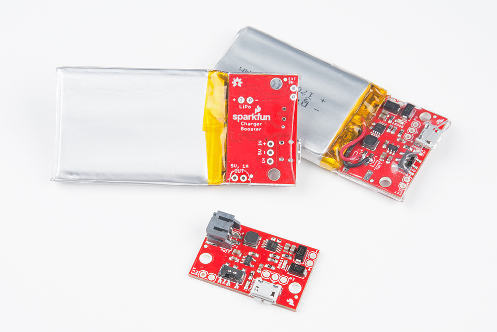
This guide shows how to use 1x charger/booster with 1x lipo to make a pack, and how to connect several packs together for greater current or voltage.
Required Materials
A Battery
You'll need a battery for each charger/booster you have. While really any LiPo will work, smaller batteries are easy to overload and don't supply much charge. It is recommended to use 1Ah batteries and larger, with the form factor most suited to our 1Ah cell.


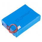

Lithium Ion Battery - 1Ah
PRT-13813A Load
Any development board that runs from a USB supply is a great thing to power with the charger/booster. It provides a stable 5 volts, and can feed power hungry boards. Take a look in the microcontrollers product category, anything with a 5V input may need mobile power.
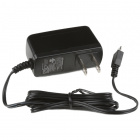
A Charger
Any old micro-B charger should do the trick, the circuit will consume up to 500mA so a computer's USB port is not recommended. You can even use the power pins to charge from a generic bench supply.
Here's some sources that can be used to connect to the on board micro-B USB connector:
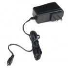
With the addition of a micro-B cable, the following USB supplies will work:
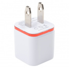
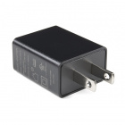
USB Wall Charger - 5V, 1A (White)
TOL-14042Or if you're in the market for a larger generic supply, try these:
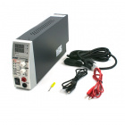
Power Supply - 80W DC Switching Mode
TOL-09291
Required Tools
You'll have to attach your load somehow! Make sure you've got a few tools on hand.
Suggested Reading
If you aren't familiar with the following concepts, we recommend checking out these tutorials before continuing.
How to Solder: Through-Hole Soldering
Battery Technologies
Working with Wire
Electric Power
What is a Battery?
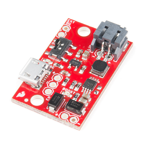
Hardware Overview
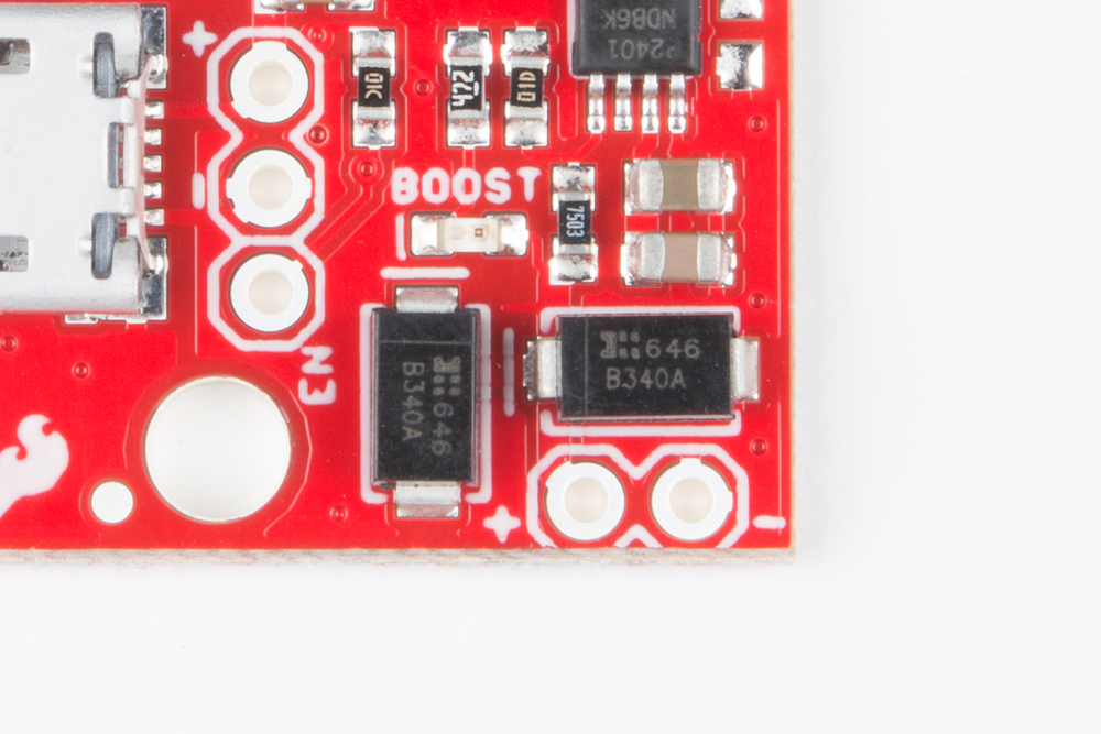
Parts of the Board
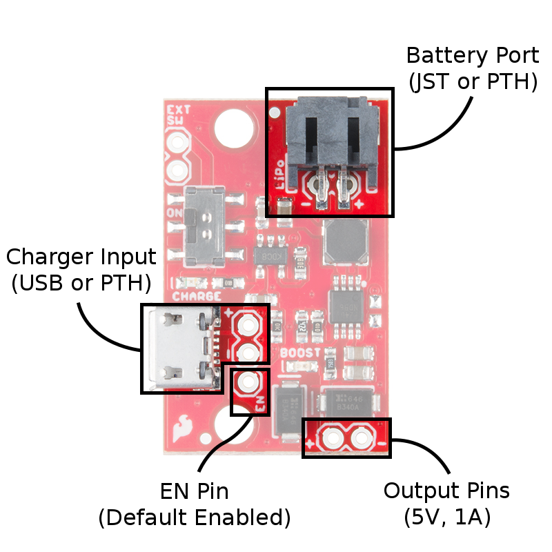
The circuit is constructed by feeding an MCP73831 charge controller IC to the LiPo battery port, and to the input of a PAM2401 boost controller. Power always flows to the boost circuit, so an enable pin is provided to allow the booster to be shut down during charging if desired. Multiple connection types are provided for the battery, charge source, and switch to allow flexibility of application.
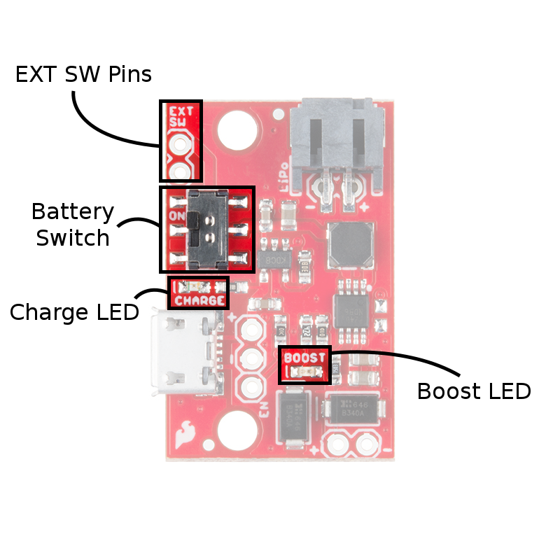
The image below shows the location of the surface mount battery switch and external switch pins which are included to provide an additional option to control the output. Two LEDs are included to provide feedback on system status.
Functions
| Item | Description |
|---|---|
| Output Pins |
Get 5V, 1A out here! The 'OUT' pins are labeled with polarity. |
| Battery Port | Insert a LiPo battery here through the JST connector or solder directly to the PTH pins underneath the connector. These ins are labeled with polarity. |
| Charger Input |
Supply 5V, 500mA here to charge. You can use a micro-B USB cable or solder directly to the PTH pins. These 'IN" pins are labeled with polarity. |
| Battery Switch | The on-board switch is a physical battery disconnect. When in the ON position, the battery is connected to the booster/charger. When flipped to the OFF position, the battery's positive lead is isolated from all electronics, and zero current will be drawn. |
| EXT SW Pins |
These run parallel to on-board battery switch contacts. A higher current switch can be connected through these pins. If you're constantly drawing large currents or want a remote battery disconnect switch, connect it here. |
| EN Pin |
The EN pin is enabled by default. This pin floats high and can be connected to ground to turn the output off. This is useful if your load circuit can't be put into low power mode for charging. |
| Charge LED |
The charge LED indicates blue when the charger IC is attempting to charge the battery. It will turn off when the battery is fully charged. Note: If current is being drawn while the battery is being charged, the charger may think the battery is never quite full and continue sourcing current. |
| Boost LED |
This LED indicates red when voltage is present on the output pins. |
Charge Status LED
The on-board blue CHARGE LED can be used to get an indication of the charge status of your battery. Below is a table of other status indicators depending on the state of the charge IC.
| Charge State | LED status |
| No Battery | Floating (should be OFF, but may flicker) |
| Shutdown | Floating (should be OFF, but may flicker) |
| Charging | ON |
| Charge Complete | OFF |
Hardware Assembly
It's easy to get started on your bench. Simply plug the LiPo into the battery JST connector, charge with a micro-B USB supply, and solder your load to the output pins. This section shows some tips and alternate ways to configure the ports.
Covered Battery Pins
There are a pair of through-holes peeking out from underneath the JST connector. Here's how to safely remove the JST and apply battery leads directly. This also lowers the profile of the circuit board.
Make several small cuts to split the JST housing using a cutter. If you try and take the whole thing off at once, you risk pulling up the pads.
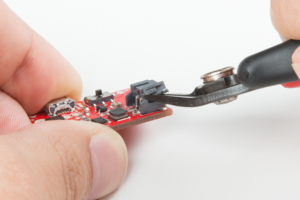
With the top removed, the pins aren't captured in the housing anymore and they can be pulled off with the soldering iron one by one.
Alternatively, you can hot air the JST connector off, but it may melt in the process.
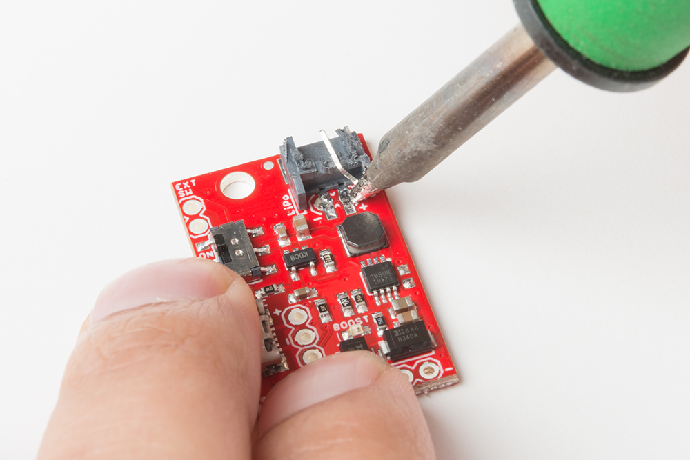
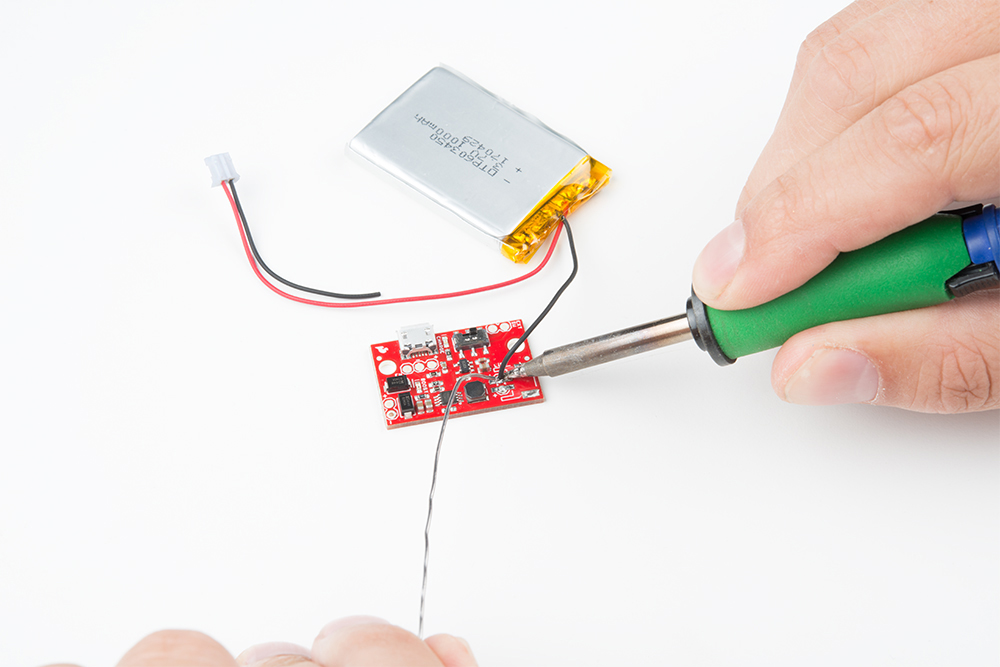
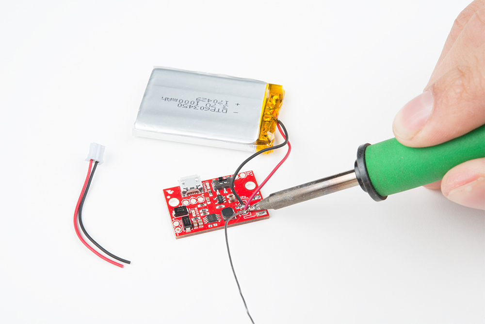
Cut and strip part of the end of the wire. Then solder the end to its respective through hole.
Charge Source Pins
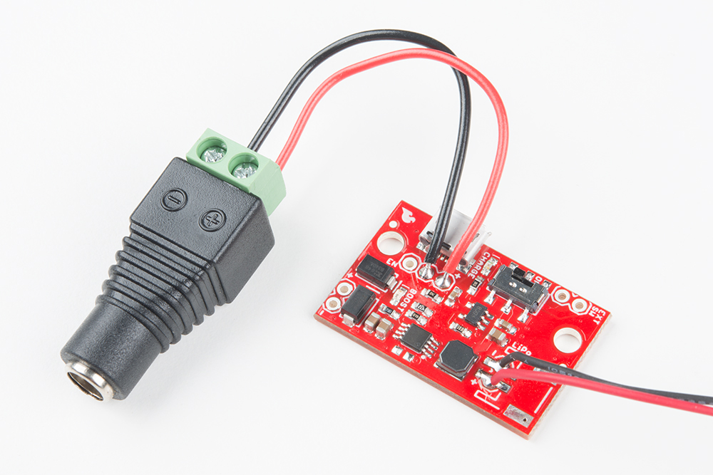
As with the JST port, you may wish to charge your lipos from a source other than a micro-B, such as a 5v barrel or bench supply. The USB port is difficult to remove without damage to the board, so leave it in and just use the '+' and '-' pins provided by soldering some hookup wire to the respective pins. To connect to a barrel jack easily, you could use a female barrel jack adapter.
External Switch Pins
The onboard switch is rated for 600mA. Using the full current output available, this rating will be violated. It won't have any immediate effect and is alright for peaky load with a nominal 500mA draw, but can lead to heat and corrosion depending on your application. If it's found to be a problem, solder a higher current switch (like the SPST rocker switch) into the 'EXT SW' pins.
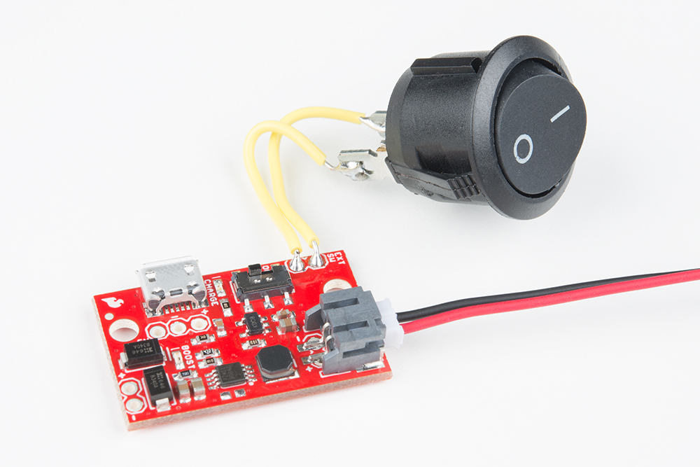
Using a high current switch, the two switches are now in parallel so either one can be used to energize the circuit. If using an external switch, be sure to leave the on-board switch in the OFF position.
Or you can jumper the external switch pins together and use the enable pin to switch power. Further details will be explained in the next section with the enable pin.
Enable Pin
Another method to remove battery load is to use the enable pin on the PAM2401. It's pulled up with a resistor on the board, so leaving it floating will default to an enabled state. To disable, it can be connected to the neighboring ground pin. The pin consumes very little current so a light duty switch (like the mountable slide switch) can be used.
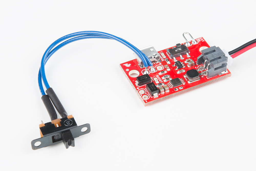
In this configuration, the onboard switch may not be necessary and can be bypassed by putting a jumper in the external switch holes. The battery won't be truly isolated though, and can drain over time. In the disable state, the current draw from the battery is about 6uA so it should take years to discharge.
Alternately, the pin can be driven by a logic source. The pin is 6V tolerant, with a logic-high threshold at 1/2 battery voltage, and a lower threshold of 0.2V.
Charging a Battery
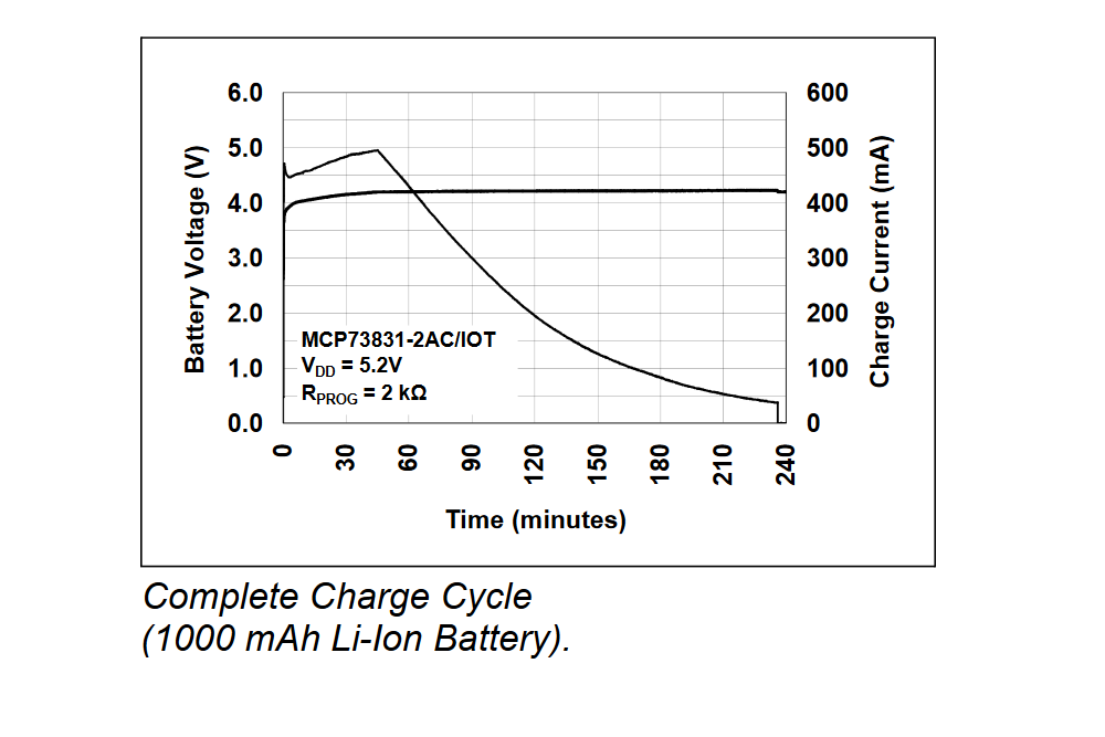
When a voltage is supplied to the charger, the MCP73831 charge IC comes alive and starts making decisions on how to regulate. First, it regulates current to 500mA until a certain voltage is reached, then it regulates voltage until current goes (close) to zero. When this happens, the charger IC shuts off.
The charger IC is making decisions based on the battery voltage and output load, and can be tricked into an invalid mode. Follow these rules to get a reliable charge:
- Turn on the battery switch before connecting the charger.
- Consume no more than 20mA from the output terminals during charging.
Connecting a Load
Eager to get your 5V? Just connect up to the output terminals!
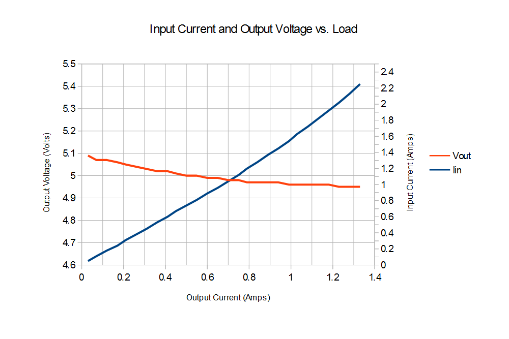
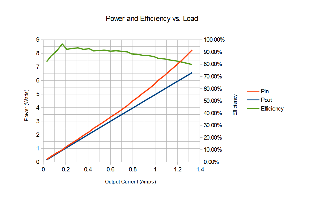
But there's always more to know. An ideal booster circuit translates all input power to output power, so if the output is providing 5V @ 1A, or 5W, 5W must also be going into the booster. But if the input voltage is down to the battery lower limit of 3V, it will require 1.666A! With an efficiency of around 85%, it requires almost 2A on the input!
Here's a graph of the charger booster's measured performance:
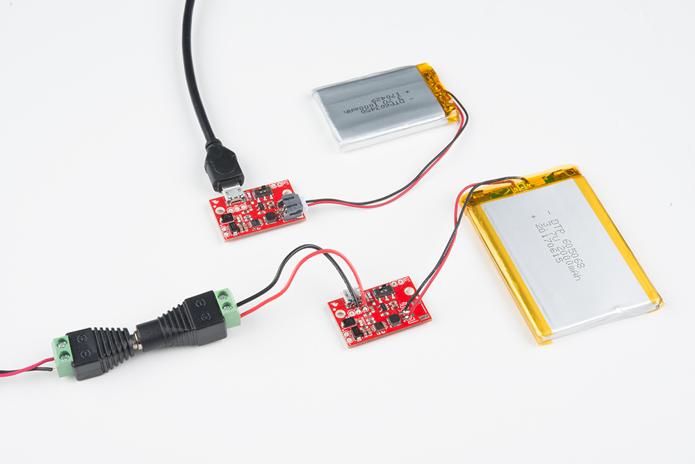
Using Multiple Charger Boosters
5V may be fine for microcontrollers, addressable LEDs, and servos, but with motors sometimes some extra kick is required. With electric motors, speed is proportional to voltage, and torque is proportional to current. So if we want robot acceleration we'd want a high torque motor (low resistance), and if we want to go fast we'll need to supply a large voltage. This section shows how to use multiple boosters and what that means for the voltage levels.
The boosters have bypass diodes placed across their outputs. This means that if a negative voltage is presented to the output, it will conduct rather than apply negative voltage to the rails.
This allows the boosters to be placed in series to create voltages larger than 5, with a couple of caveats.
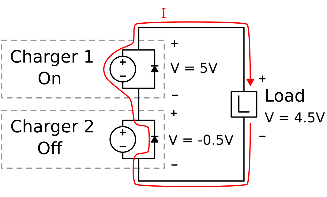
The following two diagrams show how two chargers in series interact. With both chargers on and supplying 5V, the output runs at 10V, and 1 amp is driven through the booster circuit (shown as an ideal supply).
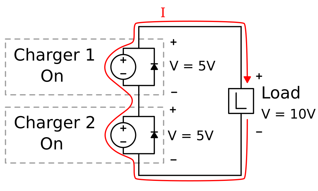
When one booster stops producing voltage, it's still in the current loop and must pass the 1A that the other booster can provide. The protection diodes allow the current to slip by, but at the cost of a diode drop. For these B340A Schottky diodes, that's about 0.5V. The output voltage is now 4.5V.
Increasing Current
Life gets a little trickier if more current is needed. By supplying your own diodes and "diode OR-ing" the outputs, you can get increased current at the cost of a diode drop, or somewhere around 4.5V. You may get away with just connecting up the outputs but run the risk of back-feeding one output with the other.

Resources and Going Further
Now that you've successfully charging LiPos and boosting them up to 5V, the world is your oyster. Go plug something in! For more information, check out the resources below:
- Schematic (PDF)
- Eagle Files (ZIP)
- Fritzing Part (FZPZ)
- MCP73831 (charger IC) Datasheet (PDF)
- PAM2401 (booster IC) Datasheet (PDF)
- SparkFun LiPo Charger/Booster - 5V/1A GitHub Repository
- SparkFun Product Showcase: LiPo Charger/Booster
For inspiration, I've built a robot using two charger boosters to get 10 volts, for a bit of extra drive speed (and fun!).
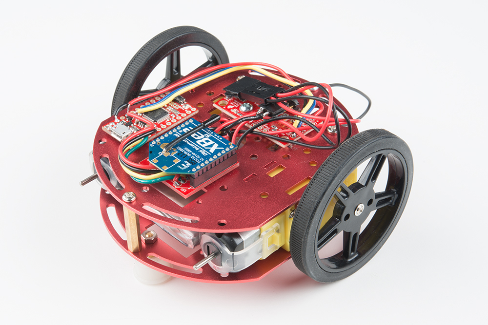
This robot is built on the with the
- Serial Controlled Motor Driver
- 2x 5V/1A Charger Boosters
- 2x 1Ah Batteries
- 1x two layer robot chasses
- 1x pair of Hobby Gearmotors
- 1x SAMD21 Mini
- 1x XBee
Or, see the Enginursday post on building a FLiR Pi Camera to see how two boosters can be used in parallel.