AST-CAN485 WiFi Shield Hookup Guide
 Alex the Giant, Ell C, JamesBM
 Introduction
What would make the AST-CAN485 even better? WiFi! In order to further the communications capabilities of the CAN485, we present the AST-CAN485 Wifi Shield. The shield is based on the Sparkfun ESP8266 thing and allows for a CAN485 module to communicate over Wifi.
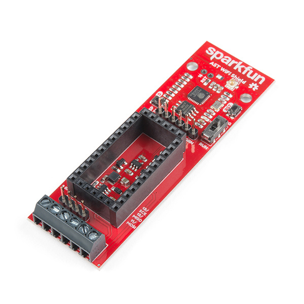
SparkFun AST-CAN485 WiFi Shield
WRL-14597Required Materials
To follow along with this tutorial, you will need the following materials. You may not need everything though depending on what you have. Add it to your cart, read through the guide, and adjust the cart as necessary.
Tools
Depending on your setup, you will need a soldering iron, solder, and general soldering accessories to solder pins to the AST-CAN485. You will also need a flat head and wire strippers to connect wires to the screw terminals.


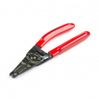
Wire Strippers - 20-30AWG
TOL-14763Suggested Reading
We recommend checking out the AST-CAN485 Hookup Guide to get started with the board. Depending on your setup, you may need to install custom libraries and board add-ons.
AST-CAN485 Hookup Guide
If you aren’t familiar with the following concepts, we also recommend checking out these tutorials before continuing.
Working with Wire
ESP8266 Thing Development Board Hookup Guide
Three Quick Tips About Using U.FL
Hardware Overview
Input Power
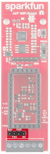
The AST-CAN485 WiFi Shield provides screw terminals for your power, RS-485 signals, and CAN bus signals, presoldered to the board for fast and secure connections.
The input voltage range is 7-24VDC. The input voltage is regulated down to 5V to supply power the CAN485 board, as well as 3.3V to power the ESP8266.
ESP8266
Based on the SparkFun ESP8266 Thing, you can use either the PCB trace antenna, or the U.FL connector if housed in a metal enclosure.
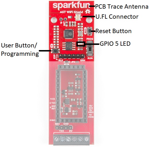
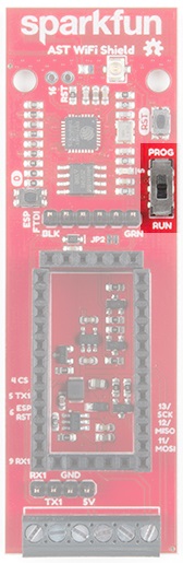
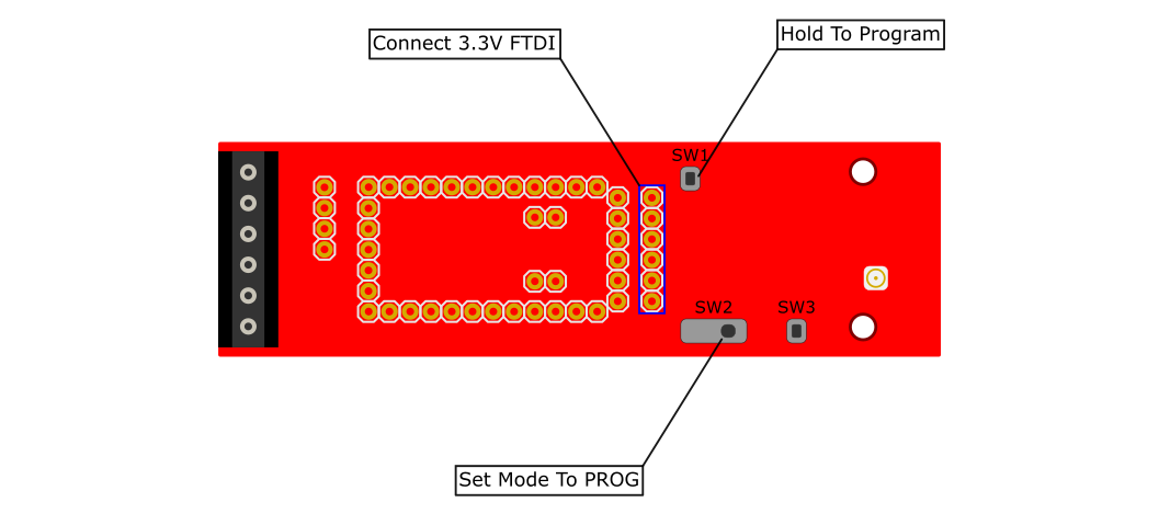
Programming Switch
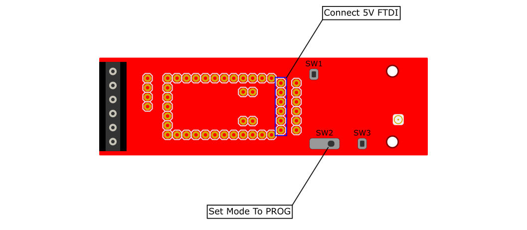
Because the UARTs are connected together for the CAN485 board and the ESP8266, a switch is used to separate the RX and TX signals. When programing either the ESP8266 or CAN485 board, move the switch over to the PROG position, and after the upload is complete, toggle the switch to the RUN position.
Speaking of programming, the ESP8266 runs off of 3.3V logic, so to program the ESP8266, a 3.3V USB to UART bridge is used.
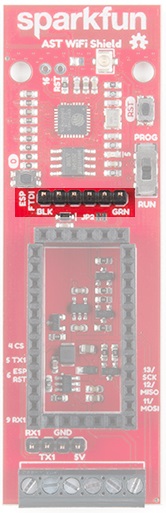
AST-CAN485 Serial Port
A header breaks out the Software Serial port used by the CAN485. This can be used as a debugging serial port or to connect other devices.
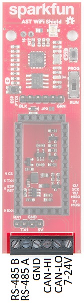
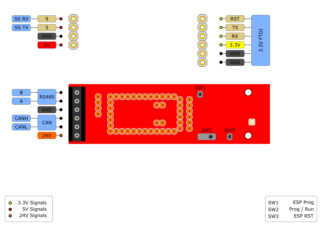
Pinouts
The pinout for the WiFi Shield is shown below:
Schematic
The schematic below shows the layout of the interconnects between an inserted CAN485 module and the integrated ESP module.
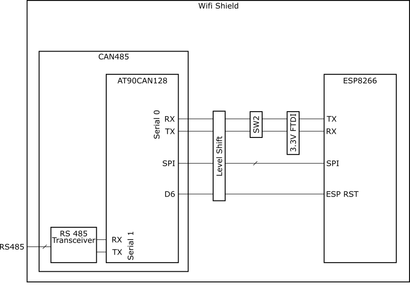
The primary interface between the CAN485 and the ESP8266 is a serial port. It operates on hardware serial port 0 on the CAN485 rather than the traditional Software Serial port. The reason for this is that it enables higher speed communications between the two devices. The trade-off of this feature is that it uses the main serial port, which is also used to program the CAN485 and is broken out on its FTDI header. This means that in order to program the CAN485 module, while it is inserted, the serial port must be disconnected. For this reason, the mode selection switch was added which allows for the rx and tx lines to be disconnected. In a similar way, the same serial port is used to both program the ESP8266 and communicate with the CAN485. The mode selection switch also enables the ESP to be programmed by disconnecting it from the CAN485.
Hardware Hookup
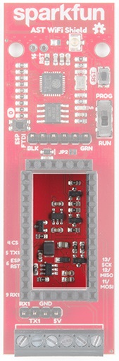
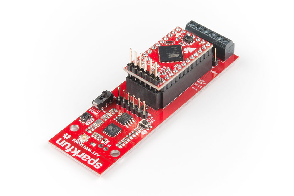
The AST-CAN485 WiFi Shield comes with headers pre-soldered to the board. Insert the CAN485 as shown with the CAN485's FTDI header close to the ESP8266.
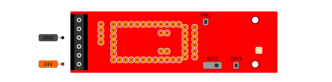
Powering The Board
The Shield can be powered through the screw terminals. While the power input is intended to be supplied with 24V, an input voltage of 7-24V may be used.
An integrated power supply regulates the 24V input power down to 5V which is used to provide power to the inserted CAN485 board. This is further regulated down to 3.3V to power the ESP module.
It is also possible to power the board using the raw input pin of the CAN485 module. However, use of an external 24V supply is recommended and is the intended use case.
Software Setup and Programming
The Programming Mode Selection Switch
The ESP and CAN485 modules are connected using a hardware serial port. The same port is used to program either of the devices. It is therefore necessary to disconnect the serial port in order to program either of the devices. A selector switch is provided in order to make this possible.
If the selector switch is set to RUN, the ESP and CAN485 are connected via a serial port. If the switch is set to PROG, the serial port is disconnected and the devices may be programmed.

Setup Arduino For ESP Programming
There are many options for programming ESP8266 based devices. The approach recommended by this guide is to make use of the ESP8266 Arduino Addon which has been developed by the ESP community. The Addon can be downloaded via the GitHub Repository or by clicking the button below.
This implementation is based on the ESP8266 Thing and the same setup instructions may be used. For more information, refer to the ESP8266 Thing Hookup Guide.
ESP8266 Thing Development Board Hookup Guide
If you have not previously installed an Arduino library, please check out our installation guide.
Installing an Arduino Library
Programming the ESP
The following process is followed in order to program the ESP module:
- Switch the mode selection switch to PROG.
- Insert a 3.3V FTDI into the FTDI header.
- Hold down the ESP programming button and upload a sketch.
- Return the mode selection switch to RUN to reconnect the devices.
Programming the CAN485
The following process is followed in order to program the CAN485 module:
- Switch the mode selection switch to PROG.
- Connect a 5V FTDI to the FTDI header on the CAN485 module.
- Upload a sketch
- Return the mode selection switch to RUN to reconnect the devices.
Examples
The WiFi Shield GitHub Repository includes a few examples which demonstrate the use of the board. After downloading the repository, open up one the examples in the Arduino IDE. Select the CAN485 as the board, the COM port that it enumerated on, and hit upload to test.
Basic Serial Example
This example demonstrates serial communication between and inserted CAN485 and the on board ESP8266. Each device has a built in LED which is controlled by the other device over the serial port. Operation is as follows:
- The CAN485 sends a command to the ESP every 100 ms.
- The ESP sets its LED on or off depending on the command.
- The ESP sends the same command back to the CAN485.
- The CAN485 sets its LED depending on the command received by the ESP.
In addition to the examples in the WiFi Shield GitHub Repository, there are a number of examples using the ESP8266 in the ESP Arduino Library. These are accessible in the Arduino IDE under File>Examples. Examples may also be found in the ESP Github Community Forum.
Resources and Going Further
For more information, check out the resources below:
AST-CAN485 WiFi Shield
AST-CAN485 Dev Board
Need some inspiration for your next project? Check out some of these related tutorials:
OBD II UART Hookup Guide
CAN-BUS Shield Hookup Guide
Getting Started with OBD-II
Or dig in further with According to Pete for more information about RS485.