1W LoRa MicroMod Function Board Hookup Guide
 Nate, santaimpersonator
Hadware Assembly
For those unfamiliar with the MicroMod ecosystem, be sure to review the Getting Started with MicroMod guide.
Getting Started with MicroMod
Processor Board and Main Board
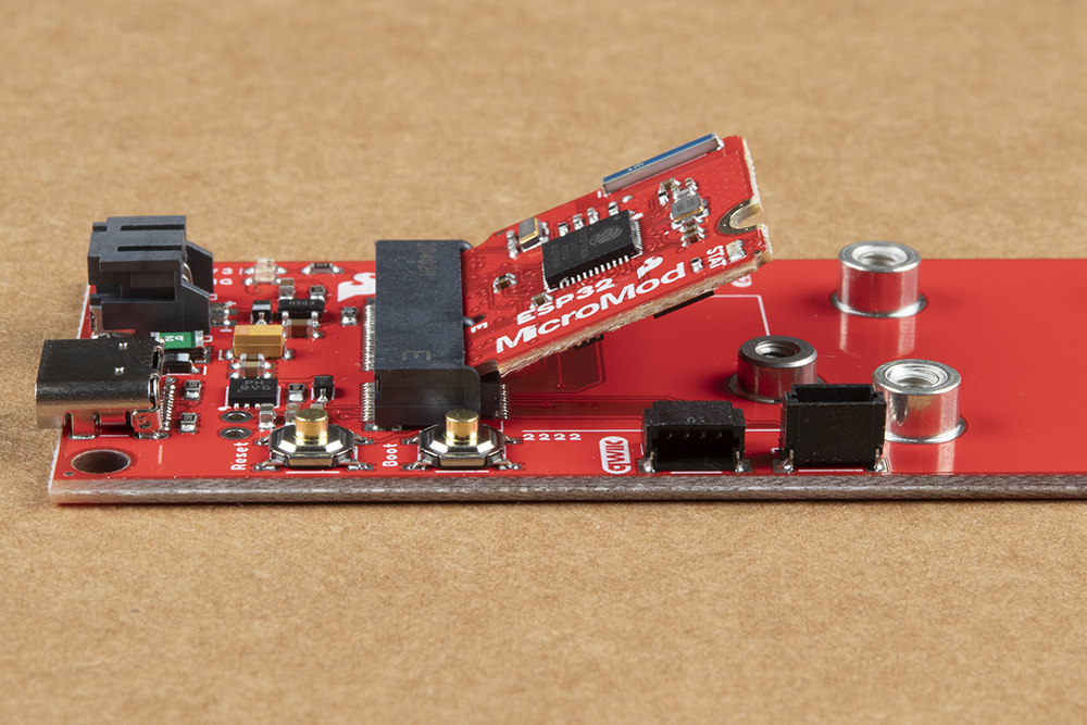
To get started users will need a compatible processor and main board. Insert the MicroMod processor board into the M.2 socket for the processor board at an angle, with its edge connector aligned to the matching slots.
When inserted properly, the processor board will rest at an angle:
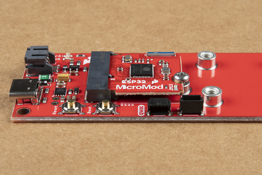
To secure the processor board, gently hold down on the board and attach the M.2 screw with a Phillip's head (PH0 or PH1) screw driver. Below, is an example of an assembled MicroMod system:
Function Board and Main Board
Warning: The LoRa module is susceptible to electrostatic discharge. Therefore, it is recommended that users a static discharge strap, like the one included in the iFixit Pro Tech Toolkit.
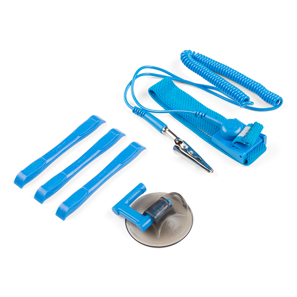
Static discharge strap in the upper righthand corner. (Click to enlarge)
Users should also address any humidity and temperature concerns, when utilizing the LoRa function board.
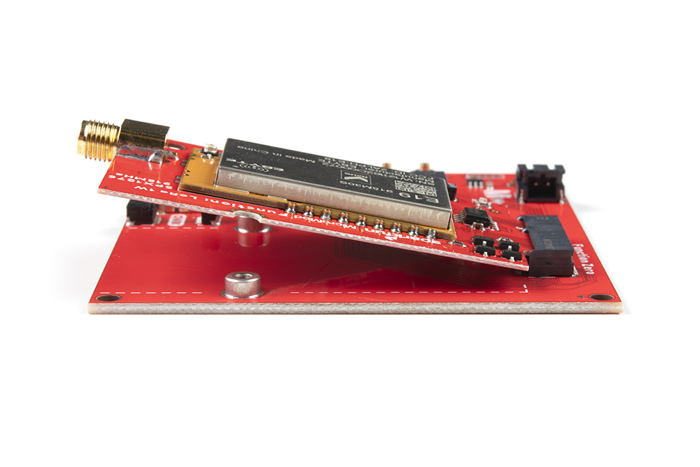
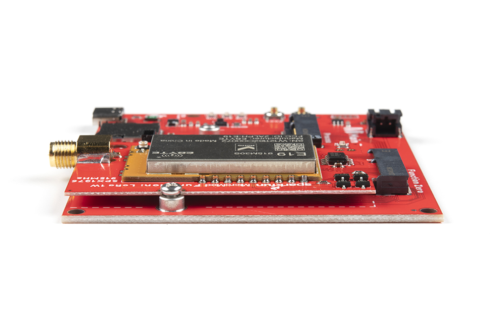
Similarly to the processor board, insert the MicroMod function board into the M.2 socket for the function board at an angle, with its edge connector aligned to the matching slots.
When inserted properly, the function board will rest at an angle:
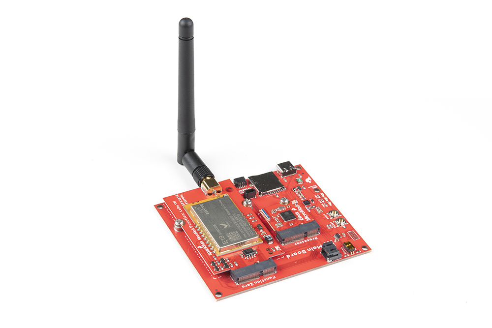
To secure the function board, gently hold down on the board and attach the M.2 screw with a Phillip's head (PH0 or PH1) screw driver. Below, is an example of an assembled MicroMod system:
Don't forget to attach the antenna for the LoRa function board. Transmitting or powering the LoRa module without an attached antenna has the potential to permanently damage the transceiver.
Main Board Example - Pin Connection Table
This table summarizes the pins utilized on the LoRa function board's MicroMod edge connector and their connections to the main board's processor pins; based on the slot that the LoRa function board is inserted to.
|
Function Board
Pin Name |
MicroMod
Pin Number |
I/O
Direction |
Description |
Main Board's
Processor Pin |
Slot 0 | Slot 1 |
|---|---|---|---|---|---|
| VCC | 72 | Input |
Power supply: 4.75~5.5V
|
- | |
| 3.3V | 73 | Input |
Power supply: 3.3V
|
- | |
| GND | 11 | - | Ground | - | |
| Power Enable | 71 | Input | Controls the 3.3V power | 68 | 66 |
| SCK | 3 | Input | SPI - Clock signal for transceiver | SCK (57) | |
| CIPO | 7 | Output | SPI - Data from transceiver | CIPO (59) | |
| COPI | 5 | Input | SPI - Data to transceiver | COPI (61) | |
| NSS | 49 (F1) | Input | SPI - Chip select for transceiver | CS0 (55) | CS1 (70) |
| RST | 55 (F4) | Input | Resets transceiver | G1 (42) | G6 (71) |
| DIO0 | 47 (F0) |
Input
Output |
Transceiver's configurable IO(Please refer to the SX1276 datasheet). | D0 (10) | D1 (18) |
| DIO1 | 57 (F5) |
Input
Output |
Transceiver's configurable IO(Please refer to the SX1276 datasheet). | G2 (44) | G7 (69) |
| DIO2 | 59 (F6) |
Input
Output |
Transceiver's configurable IO(Please refer to the SX1276 datasheet). | G3 (46) | G8 (62) |
| TXEN | 51 (F2) | Input | Transceiver's RF control switch: The TXEN pin is in high level, RXEN pin is in low level when transmitting. | PWM0 (32) | PWM1 (47) |
| RXEN | 53 (F3) | Input | Transceiver's RF control switch: The RXEN pin is in high level, TXEN pin is in low level when receiving. | G0 (40) | G5 (73) |
| SCL | 21 | Input | I2C - Clock signal for EEPROM | SCL (14) | |
| SDA | 19 |
Input
Output |
I2C - Data signal for EEPROM | SDA (12) | |
| EEPROM WP | 40 | Input | Controls the write protection pin for the EEPROM. Pull low to enable. | - | |
| EEPROM A0 | 6 | Input | Controls EEPROM's I2C address configuration. | - | |
| EEPROM A1 | 4 | Input | Controls EEPROM's I2C address configuration. | - | |
| EEPROM A2 | 2 | Input | Controls EEPROM's I2C address configuration. | - | |
Programming
To program the processor board utilized on the Main Board; connect the board to a computer with a USB-C cable. Depending on the processor board, users may need to install drivers (if they have not done so already).
Note: Make sure that the correct board definitions are installed in the Arduino IDE, for the selected processor board. For help installing board definitions, use the MicroMod processor boards landing page and review the associated hookup guide for that hardware.